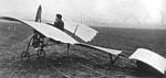
Designed by a collective [Аэроплан АПВ (Коллективный)] in 1909 under Alexander Petrovich Vernander (Александр Петрович ВЕРНАНДЕР – 1844-1918), professor of the Military Academy of Engineering, then second chief of the engineering bureau in Gatchina. Among the seven aircraft constructed in Gatchina one was christened „ласточку“ – swallow – a triplane that followed the Wright design but with curved wings, its propulsion consisting of a 25 hp REP engine, that drove two inward slanted propellers via bevel gear, to centre the air stream onto the rudder’s sides. Construction began in St. Petersburg in 1909, but the machine was not completed when construction ended in 1910.
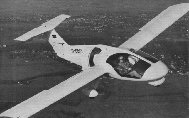
Built in collaboration with Grumman-American the Fanliner two-seat light aircraft with Wankel rotary engine, first flown in 1973. Grumman American decided not to market the Fanliner in the U.S. but VFW Fokker did borrow the Cheetah wing and horizontal tail to build their pusher. It was re-engined in 1976 with a Dowty Rotol ducted propulsor. Based on the Fanliner’s promise, the Federal German Government awarded a contract for two Fantrainer prototypes with ducted fan engines, first flown in 1977 and 1978.
The success of the H3 version resulted in the construction of a follow-on 1969 H5 prototype which bore marked similarities to its predecessor. The H5 incorporated many H3 components, including rotor blades (although 0.6m longer), a modified H3 landing gear, along with H3 controls, tail, and tail boom. The cabin could also be opened with left-side seats capable of folding for litter loading and unloading. The larger H-5 cabin had five seats.
Like the H3, there was also no hydraulic system with the H5.
It was intended that the H-5 would be followed by the H-7 7/8 seater (construction of which was apparently started but not completed) and the much larger H-9. As it turned out, however, further development was abandoned in 1972 following the merger of VFW and Fokker.
In 1960 VFW began research to develop a VTOL concept that exceeded the capabilities of current helicopters. More than a dozen different concepts were investigated, and the concept that evolved promising the best growth potential, productivity, speed, and cost effectiveness was the H3-E Compound Helicopter configuration.
The H3-E was built with a mission as a three-seat executive transport, two-stretcher ambulance aircraft, or an agricultural system with a payload of up to 315kg.
The design incorporated a compressed air and blade tip-drive rotor. The separate forward-thrust system consisted of fuselage-mounted fans.
The H3-E had a take-off weight of about 950kg and an empty weight of 500kg. The craft provided a payload weight of 265kg. The model had the capability of carrying a payload of almost 270kg with a fuel load of 205kg.
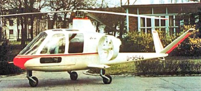
The completely enclosed fuselage was built around an aluminum alloy load-bearing keel which supported the cabin, landing gear, and engine bay structure, low-set tailboom with a V-tail, and a tricycle undercarriage. The cabin skin was fabricated of a glass-fiber reinforced plastic laminate.
The power unit was an Allison 400 shaft horsepower turbine engine which had a dual purpose. First, it was used to drive a centrifugal compressor in the hover mode. A duct delivered the compressed air through a flexible sleeve to the air distributor around the rotor shaft. Then, the high-pressure air traveled via flexible hose into the roots of the fully-articulated blades.
The overhead rotor consisted of a three-blade configuration and the blades used the NACA 23015 airfoil section. The speed range for the rotor varied from 280 to 480 revolutions per minute with a maximum loading of 15.7kg/sq.m.
When the air reached the end of each rotor, it was thrust through flush-mounted slot nozzles. A gearbox contained two bevel gears for the fans and a brake on the compressor shaft for switching the power to the compressor or to the fans. The mechanical layout of the system effectively eliminated the need for conventional transmission and driveshaft systems, hydraulic systems, and a tail rotor.
The technique to achieve near-vertical flight occurred when the rotor was slightly rotated in a standard helicopter style. With the increase in speed, the side-mounted fans were caused to free-wheel within their containing shrouds.
At a certain point in the trajectory, a decision that was made by the pilot, the transformation to full utilization of the fans could be made. Since the fans were already in a windmilling situation, the transition to full fan speed took only about two seconds to accomplish.
Hovering stability was mainly affected by blade hinge offset, blade pitch, angular velocity, disk loading, gross weight and mass moment of inertia of the aircraft,
Early in its program the H3-E underwent a number of test programs. An extensive blade fatigue test attempted to simulate the temperature and pressure cycles inside the blades. The test rig was fully automated, and every five minutes, the temperature and pressure increased and stabilized for 45 seconds before the blade vibrated.
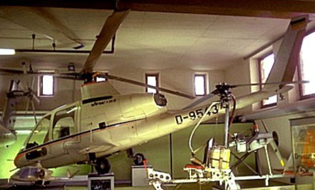
The only two prototypes of the H3 were constructed in 1968. Before flight, though, there were considerable ground shake tests accomplished. A sophisticated test rig excited the rotor head with a constant force independent of frequency. Ground tests also showed that the vehicle had certain mechanical instabilities at high rotor speeds. The first of two prototype H-3s (H3-E1, D-9543) flew in early 1970 without the external fan propulsion units.
Engine: 1 x Allison 250-C20 turboshaft, 300kW Main rotor diameter: 8.70m Rotor disc area: 60 sq.m Length with rotors turning: 9.29m Max height: 2.5m Landing gear track: 2m Max take-off weight: 968kg Empty weight: 495kg Max speed: 300km/h Max cruising speed: 250km/h Normal cruising speed: 242 kph Max vertical rate of climb: 2m/s Service ceiling: 3900m Endurance: 2hr
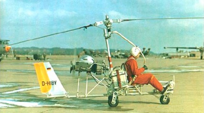
In 1968, VFW (Vereingte Flugtechnische Werke) built an experimental open gyrocopter modelled on the Bensen B.8M. This VFW-H2 was unusual in having ducted rotor blade tip jets supplied from the 72hp McCulloch engine. The engine itself was mounted behind the pilot and drove a two-blade pusher propeller.
The H-2 (D-HIBY) was followed by a more sophisticated machine – the H-3 Sprinter which had a completely enclosed fuselage structure with a three-seat cabin, slim low-set tailboom with a V-tail, and a tricycle undercarriage.
A two seat fully enclosed autogyro. Side by side seating. Composite body, airframe of square T-6 aluminium tubing, V tail. Engine: Rotax 582 or 618. Prop: 72” IvoProp carbon fibre, ground adjustable. Rotor blades: 27’ Dragon Wings.
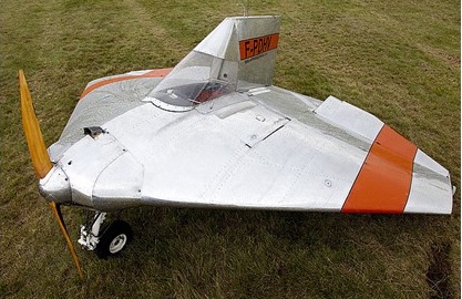
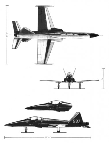
Revealed in June 1987, the Venga TG-10 is a privately financed composite-construction, single engined jet trainer/light attack aircraft with tandem seating. Funding difficulties slowed the programme significantly in late 1987. The first flight has consequently been rescheduled several times, and had not taken place by July 1989.
In September 1988 Venga announced a joint-venture agreement with a Malaysian partner who were to produce the TG-10 in Sabah State, East Malaysia. Royal Malaysian Air Force interest was claimed, although no orders had been placed by July 1989.
An all-composites airframe and modular construction are intended to give the TG-10 an estimated flying life of about 10000 hours, due to a considerable reduction in the corrosion and fatigue problems associated with aircraft of metal construction. Its configuration also incorporates low-observables design features intended to improve its survivability. It will be repairable in the field, using replacement major components and quick-change engine modules, and will be operable from roads, grass or unprepared airstrips, with mission capability not only for its primary role as an `all-through’ trainer but also, in single-seat form (with the rear cockpit module removed), as a light ground attack aircraft.
AIRFRAME: Construction utilises a modular, all-composites structure designed for ease of repair in the field, built from pressure formed foam core laminates bonded together into a single lightweight moulded unit. Materials used are layers of aircraft grade glassfibre cloth bonded to a core of PVC foam (Klegecel or Divinycell) in a vacuum process using various resin matrices. Primary structure built entirely of composites materials, with extensive use of carbonfibre for high stress and other critical areas, though use of carbonfibre reinforced aluminium alloy (eg for main spars) is a customer option.
WINGS: Cantilever low-wing monoplane, with 2o 30′ dihedral from roots. Trailing-edge flaps are operated electrically via Commercial Aircraft Products actuators. Differentially operating ailerons, each with trim tab.
FUSELAGE: Modular structure (see `Airframe’ paragraph), of similar general appearance to Northrop F-5E. Electro-hydraulically actuated airbrake beneath fuselage.
TAIL UNIT: Low-set, sweptback tailplane with slight anhedral. Twin non-swept, outward canted fins, with inset rudders, forward of horizontal surfaces. Trim tabs in elevator and each rudder.
LANDING GEAR: Retractable tricycle type, with electro-hydraulic actuation; nosewheel retracts forward, mainwheels inward into fuselage. Wheel sizes 5.00-5 (nose), 6.00-10 (main). Nosewheel steerable through 30o. Mainwheels have hydraulic brakes and parking brake.
POWER PLANT: Prototype powered by one 13.01 kN (2925 lb st) General Electric J85-GE-5 turbojet; standard engine for basic production version will be an 11.12 kN (2500 lb st) Pratt & Whitney Canada JT15D-4C turbofan, but customer options will include General Electric CJ610 or Rolls-Royce Viper 632 or 680 turbojets. Intakes are each fitted with a large splitter plate, and are designed to inhibit foreign object damage. Fuel system, designed to permit fully aerobatic manoeuvres, comprises three fuselage cells with total usable capacity of 1223 litres (323 US gallons; 269 Imp gallons). A 265 litre (70 US gallon; 58 Imp gallon) drop tank can be carried on the fuselage centreline station in the single-seat attack configuration.
ACCOMMODATION: Standard trainer has tandem accommodation for pupil (in front) and instructor on UPC zero/zero ejection seats under jettisonable bubble canopy, with internal screen between cockpits. Seats are reclined, adjustable horizontally and vertically, and can accommodate back-type parachutes. Dual controls standard, except for switches for fuel pumps, weapon control panel and parking brake; in lieu of these, rear panel has a full set of indicators for the weapons system, an override switch to prevent firing, and a parking brake indicator. Rail mounted rear seat and rear instrument panel module are easily removable to permit quick conversion to single-seat light attack configuration. Cockpit(s) fully air-conditioned, but not pressurised; latter may be offered later as a customer option.
SYSTEM: 28V DC electrical system, powered by a standard starter/generator and Gates Energy Products lead-acid battery, with second battery for emergency backup. Power sources are coupled to three busbars in front cockpit (main, avionics, and emergency) containing trip-free circuit breakers. NATO type external ground power socket. Normalair-Garrett diluter demand oxygen system, capacity 225 litres (8 cu ft).
AVIONICS AND EQUIPMENT: Avionics include two VHF com, intercom, VOR/ILS/marker beacon receiver (front), VOR/LOC nav (rear), ADF, transponder, and DME. Full IFR capability, with electrically driven gyro instruments; main directional gyro is a King slaved type unit. Provision for HUD, radar altimeter, nose radar or other avionics to customer’s requirements. Standard cockpit instrumentation and equipment includes ASI (two), VSI (two), encoding altimeter, standard altimeter, clock (two), horizon gyro (two), turn and slip indicator (two), accelerometer (two), angle of attack indicator, pictorial navigation indicator, magnetic compass (two), DME indicator (two), ADF information display (two), first aid kit, IFF transponder, fire extinguishing system, and internal/external lighting.
ARMAMENT: One centreline and four underwing hardpoints, each stressed for loads of up to 181.5 kg (400 lb), for weapons, fuel tank (centreline only), survival or rescue packs, or other stores, subject to a max external load of 845 kg (1864 lb) in single-seat attack version. Weapons specified at present include up to three Portsmouth Aviation 7.62 mm FN gun pods with 450 rds/gun; up to three HMP 0.50 in Browning gun pods with 250 rds/gun; two GIAT 20 mm M621 gun pods with 150 rds/gun; various rocket launchers (Matra F2 with six 68 mm, Aerea AL 18-50 with eighteen 2 in, AL 8-70 with eight 2.75 in FFAR, AL 6-80 with six 81 mm, LAU-32 with seven 2.75 in FFAR, SNIA 2 in, Brandt 7 with seven 68 mm, or SURA-D 81 mm); SAMP 32 kg or 50 kg general purpose or 120 kg fragmentation bombs; 11 kg Mk 76 practice bombs; or a 70 mm automatic panoramic IRLS reconnaissance pod.
Venga reports that it has received letters of interest from five countries, involving approximately 160 aircraft. Rollout of the TG-10 prototype was anticipated in the Summer of 1989, subject to funding availability, and recent joint venture arrangements are claimed to have ensured funding to completion at about that time.
The first prototype was to be assembled in Montreal, but the US Thunder group was responsible for the engineering design of the TG-19, and the moulds were manufactured at Scottsdale, Arizona.
Venga was a struggling company throughout the ’90s. When the Venga TG-10 prototype was burned, it had a drastic impact on them. This was their major project that had been presented to the world. There was a decent degree of interest, and they had even formed a partnership. All of this changed on that day in May of 1998.
Without an actual prototype, there was no reason for anyone to have even the slightest interest. This is especially true given the fact that there were many other aircraft available now for a comparable price.
Venga TG-10 Wing span: 8.23 m (27 ft 0 in) Wing area: 12.54 sq.m (135.0 sq ft) Wing chord at root: 2.29 m (7 ft 6 in) Wing aspect ratio: 5.4 Length overall: 11.89 m (39 ft 0 in) Fuselage Max width: 1.42 m (4 ft 8 in) Height overall: 4.04 m (13 ft 3 in) Tailplane span: 3.96 m (13 ft 0 in) Wheel track: 3.05 m (10 ft 0 in) Trailing-edge flaps (total): 1.30 sq.m (14.0 sq ft) Rudders (total, incl tabs): 1.11 sq.m (12.0 sq ft) Tailplane: 1.67 sq.m (18.0 sq ft) Elevators (total, incl tab): 1.67 sq.m (18.0 sq ft) (A: two-seat trainer, B: single-seat attack): Weight empty, equipped (incl unusable fuel): A: 1288 kg (2840 lb) B: 1047 kg (2308 lb) Max usable internal fuel: A, B: 908 kg (2002 lb) Max external stores load: A: 277 kg (610 lb) B: 845 kg (1864 lb) Max T-O weight: A: 2645 kg (5832 lb) B (without external stores): 2041 kg (4500 lb) B (with max external stores): 2886 kg (6364 lb) Performance: (estimated: prototype with J85 engine at 2645 kg; 5832 lb max T-O weight): Max level speed: at S/L, ISA: 485 knots (899 km/h; 558 mph) at 9150 m (30000 ft), ISA: 450 knots (834 km/h; 518 mph) Stalling speed: 78 knots (145 km/h; 90 mph) Max rate of climb at S/L, ISA: 2134 m (7000 ft)/min Time to 9150 m (30000 ft): 7 min 12 s T-O run at S/L, ISA: 186 m (610 ft) T-O to 15 m (50 ft) at S/L, ISA: 402 m (1320 ft) Ground turning radius, all wheels rolling: 6.10 m (20 ft 0 in) Max range: internal fuel only, 10% reserves: 950 nm (1760 km; 1094 miles) with c/l drop tank, no reserves: 1271 nm (2355 km; 1463 miles) Max endurance at 9150 m (30000 ft): 2 h 30 min