Designed by Joaquin S Abreu, the one AE-5 built, N592, had a steel tube fuselage and wood-framed parasol wing. It was a high wing 2 place monoplane. The engine and belly fuel pod was a detachable unit that could be released from the cockpit in case of fire or a dire emergency, and the ship would become a glider. In its first test in 1929, this was demonstrated at Alameda CA. From 5,500′ the motor and tank unit was jettisoned, falling into sand dunes by the bay, and the ship glided for about 15 minutes before heading for the runway. There a group of people running toward the oncoming ship forced pilot Reed Vowles to swerve the plane and nose it into soft ground, sustaining minor damage.
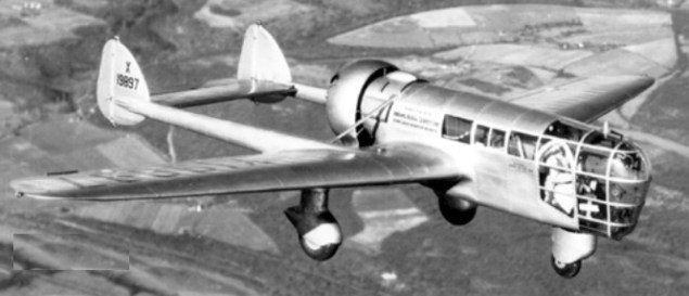
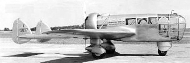
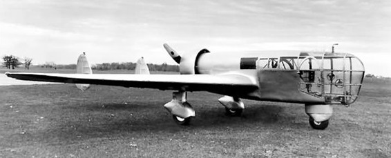
Explorer – a twin-boom pusher monoplane of 1936, to the design of Talbert Abrams. Incorporated a fully-glazed nose.
Designed by Talbert Abrams and Kenneth Ronan, a prototype, X19897, was constructed by Ronan & Kunzl of Marshall MI. Created as a photo-survey plane with a service ceiling of 21,000′, first flown in November 1937, it was repowered with 450hp supercharged Wright in 1938. Only the one was ever built.
The Explorer is stored with the Smithsonian National Air and Space Museum, awaiting restoration.
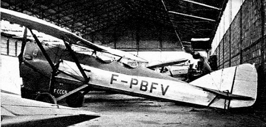
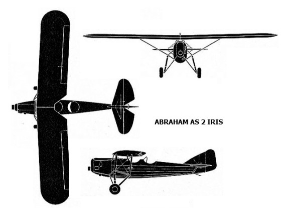
In 1930 Edmond Abraham built the Iris I, a 2 seat parasol monoplane. This was modified as the Iris II with a Renault, 95hp engine.
French regulations evolved and the craft ended at Avignon Chateaublanc.
In 1930 Edmond Abraham built the Iris I, a 2 seat parasol monoplane. This was modified as the Iris II with a Renault, 95hp engine.
French regulations evolved and the craft ended at Avignon Chateaublanc.
Iris II Engine: Renault 4Pb, 95 hp Prop: 2 blade wooden Wingspan: 9.8m / 37 ft 2 in Length; 6.97m / 22 ft 6 in Height: 2.5m / 7 ft 7 in Wing area: 15 sq.m / 161 sq.ft Empty weight: 467 kg / 1027 lb MAUW: 760 kg / 1672 lb Max speed: 180 kph / 113 mph Range: 400 km / 250 miles
Constructed during 1909–1910 at Kassel-Waldau by Carl Abelmann; the son of a Cologne factory owner. The monoplane had both tractor and pusher propellers with extra lift propellers (Hubschrauben). Carl Abelmann, FlAbt 254(A), along with his observer Ltn Heirich Schönberg, were the victims of Georges Guynemer on April 14, 1917 – his 36th victory.
Made by, Keiiche Abe, a teacher in Hokkaido, Japan, in 1977, the Mini-gyro-sail-motorplane has Bensen parts, Abe airfoils and a Toyota engine. It cruises at 48 mph, takes off in 510 feet, and lands in 160 feet. It cost around $1000.
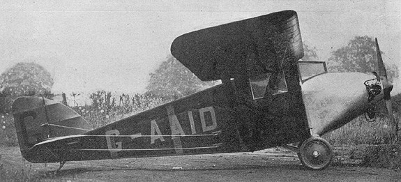
The ABC Robin was a British single-seat light aircraft designed by A. A. Fletcher in 1929. It was a high-wing, single-seat monoplane of conventional taildragger configuration. The cockpit was fully enclosed, the first lightplane to be so equipped in Britain. It was designed at the request of T.A.Dennis (Managing Director) specifically to use the firm’s 30–40 h.p. Scorpion engine.
Construction was primarily of wood with metal confined to fittings and a few highly stressed parts. The fuselage was constructed as a wooden box consisting of four spruce longerons with thin plywood covering with light internal bulkheads. The wood-framed wings, of RAF 34 section, were hinged at their inner rear corners to the top of the fuselage and supported by tubular struts in ‘Vee’ formation to the lower longerons of the fuselage. The tail was also wood-framed and both wings and tail were covered with doped fabric.
The Robin, registered G-AAID, was built by ABC Motors Limited at Walton-on-Thames in 1929. The first flight was at Brooklands in June, and it was displayed at the Olympia Aero Show in July. It was modified later in the year with the windscreen moved back to allow access to the fuel filler caps from the outside, and with an enlarged fin and rudder. The sole Robin built was scrapped at Brooklands in 1932.
Engine: 1 × ABC Scorpion II, 40 hp (30 kW) Length: 17 ft 7 in (5.36 m) Wingspan: 25 ft 4 in (7.72 m) Wing area: 110 ft² (10.23 m²) Height: 5 ft 9 in (1.73 m) Empty weight: 415 lb (188 kg) Loaded weight: 680 lb (308 kg) Maximum speed: 105 mph (91 knots, 169 km/h) Range: 340 mi (295 nm, 545 km) Service ceiling: 17,000 ft (5,200 m) Rate of climb: 750 ft/min (3.8 m/s) Wing loading: 7 lb/ft² (34 kg/m²) Power/mass: 0.058 hp/lb (100 W/kg) Crew: one
The rationale of the name, A B C, is firstly, that it contains the initials of those associated in the development of the machine; Anient, Buranelli & Carisi, and, secondly, that it expresses the constructional simplicity, which is a prominent feature of the machine.
In April 1915, a machine to be known as the A B C Military Biplane (pusher”), was to make its debut shortly. Mr. Robert S. Anient, a well-known newspaper artist, was directing the exploitation, and Messrs. John Carisi and Yincent J. Buranelli were responsible for the design and construction of the machine.
The airplane was designed to especially facilitate quick assembling, and the machine, being a pusher, has a splendid range of vision, and for military work gives the gunner a sweep of 180 deg. The machine is a two-seater, seats arranged side by side, and dual controls are provided. The fuselage is covered entirely with duralumin. The landing chassis has four wheels, two in front, to facilitate running over rough ground.
The top wing warps from the end uprights out, similar to a monoplane. The power plant was to be a 100-hp specially built A B C aviation motor.
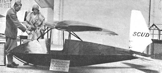
E.D.Abbott, Farnham, produced Mignet Fleas and Baynes Scud during 1935-36. Of conventional construction, the prototype was built by Brant Aircraft Ltd, Waddon Aircraft Factory, Croydon, Surrey. The prototype featured a wire trailing edges to the wings and empennage (fluted). The prototype first flew on 11 January 1931 at Totternhoe, Beds.
Production Scud I were built by Abbott-Baynes Sailplanes at Farnham, price in 1931 at £95 ex-works. No airbrakes or flaps were fitted. Undercarriage was a main skid only.
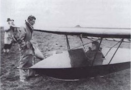
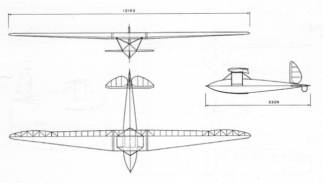
The Scud 2 designed by L.E. Baynes was a development of the Scud 1. The prototype first flew at Askam-in-Furness on 27 August 1932. With main skid undercarriage and a tail bumper, no airbrakes or flaps were fitted. They were priced at £150 ex-works in 1932.
In 1935, piloted by Mungo Buxton, a Sud 2 held the British height record of 8750 ft / 2666 m.
Scud 2 – L.E. Baynes with G. Mungo Buxton in cockpit before 29 September height record at Sutton Bank
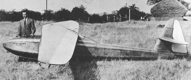
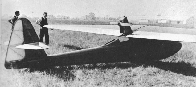
Baynes’ Scud 3 was designed specifically to include such a launching aid but was also capable of high-performance engineless flight. Without an engine it was known as the Abbott-Baynes Scud 3; with the engine, as the Carden-Baynes Auxiliary. Since the engine could be removed or retrofitted the nomenclature sometimes became confused. The Auxiliary is historically significant as the first sailplane with a retractable engine and propeller CG Grey, respected editor of The Aeroplane, wrote after the first flight of the Scud 3, piloted by Dr Dewsbery “Dewsbery now holds the certainly unique position of being the first aviator to retract his motor and airscrew while flying.”
The Scud 3 was an advanced sailplane in its time, all wood and with a long-span wing with heavy taper on the leading edge. The airfoil section was designed by Baynes and varied from the wing root outwards. At the centre it had a flat undersurface, making the wing thick and easy to strengthen as well as reducing wing root interference drag. Outwards, as thickness, chord and incidence reduced, the lower surface became increasingly concave, producing reflex camber. These features were intended to ensure that the stall started at the centre of the wing rather than at its tip. The ailerons were of the differential type. The wings were readily demountable for transport.
Carden-Bayne Auxiliary retracted
The fuselage was flat sided and plywood covered apart from near the nose; upper and lower surfaces were curved and again ply covered. The rounded nose was built up with a double layer of narrow spruce strips placed diagonally. The single cockpit was well ahead of the wings and their mounting pylon had a fairing which extended aft of the trailing edge and contained the engine. At the rear there was a tall fin with an unbalanced rudder. The tailplane was mounted about one third of the way up the fin, carrying split elevators; like the wings it could be removed for transport. The undercarriage was just a single wheel mounted partly inside the fuselage.
The unique feature of the Auxiliary was the powerplant and its mounting. Carden had selected a 250 cc single-cylinder, air-cooled two-stroke Villiers motorcycle engine. He encouraged Villiers to persuade this engine to run inverted, in order to put the propeller line to the top of the mounting and thus minimise air resistance. This proved satisfactory, and many hours of testing with the cowling in place and at full throttle showed there were no overheating problems. A small fuel tank was fixed above the crankcase, at the top of the engine. Carden also designed the engine mounting that enabled the engine and its propeller to be swung out of its housing and into action. The engine was hung to the top of the pylon bulkhead, just ahead of the trailing edge, on a diagonally cross-braced pair of tubes from the hinge to the crankcase and with V-tubes to the cylinder head.
In use the engine and propeller were vertical, the latter having a small diameter to clear the lips of the open top of the fuselage. The engine was held in position by a diagonal longitudinal member attached to a nut on a screw thread which could be rotated with a crank in the cockpit. As the lower end of this member moved forward, the engine rotated into the horizontal position, its fairing closing the fuselage opening. The propeller was indexed to stop in a vertical position and its lower tip moved forward on retraction into a slot in the bulkhead, whilst the other blade pressed on a lever that caused hinged fairing doors, previously held open with springs, to close over it. With the engine retracted, the rear of the pylon was as smoothly faired as on any conventional sailplane.
One other unusual and possibly unique feature of the Auxiliary was that it had a secondary throttle on the port wing tip, so that the pilot could easily taxi the aircraft whilst supporting the wing.
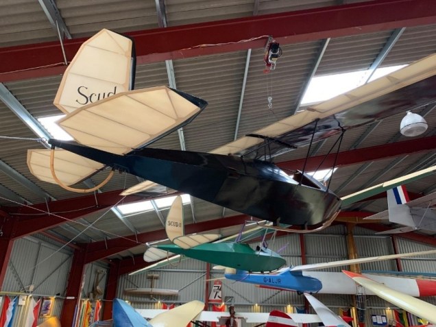
The Scud 3 first flew as an unpowered aircraft in May 1935, and took off under its own power on 8 August that year. It got airborne in 450 ft (140 m) climbing to 2,000 ft (610m) in 15 minutes before Dr Dewsbery retracted the engine and flew it as a sailplane. This first aircraft was still fitted with its engine in 1949, when it was registered as G-ALJR, but in 2010 was flying as an unpowered sailplane. Photographs from the 1930s and ’40s suggest that at some point the closing mechanism of the rear fairing was altered and a fixed slot provided for the propeller. A second Scud 3 was built in 1935 but not fitted with an engine until 1949, when a more powerful 350 cc Villiers was installed until late in 1951. It is on display at the Gliding Heritage Centre.
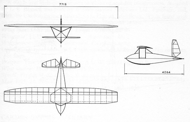
Scud I Wingspan: 7.72 m / 5 ft 3.76 in Length: 4.06 m / 13 ft 4 in Wing area: 7.90 sq.m / 85 sq.ft Aspect ratio: 7.5 Wing section: Gottingen 535 mod. Empty weight: 46.72 kg / 103 lb AUW: 114.76 kg / 253 lb Wing loading: 14.54 kg/sq.m / 2.98 lb/sq/ft Max L/D: 15 Min sink: 0.98 m/sec at 48-56 kph / 3.23 ft/sec at 30-35 mph
Scud 2 Wing span: 12.19 m / 40 ft 0 in Wing area: 9.29 sq.m / 100 sq.ft Aspect ratio: 18 Wing section: Gottingen 652 Length: 5.31 m / 17 ft 5 in Empty weight: 68.04 kg / 150 lb AUW: 145.15 kg / 320 lb Wing loading: 15.63 kg/sq.m / 3.2 lb/sq.ft Max L/D: 22 Min sink: 0.67 m/sec / 2.2 ft/sec
Scud 3 Wingspan: 45 ft 6 in (13.87 m) Wing area: 120 sq ft (11 m2) Aspect ratio: 16 Airfoil: Special Baynes section Length: 22 ft 6 in (6.86 m) Height: 4 ft 0 in (1.22 m) Empty weight: 117.94 kg (260 lb) Gross weight: 226.8 kg (500 lb) Maximum speed: 40 mph (65 km/h, 35 kn) Cruise speed: 35 mph (56 km/h, 30 kn) Stall speed: 25 mph (40 km/h, 22 kn) Maximum glide ratio: 1:22 Rate of sink: 132 ft/min (0.67 m/s) Lift-to-drag: 24:1 Wing loading: 18.31 kg/m2 (3.75 lb/sqft) Crew: 1
Scud 3 Wingspan: 48 ft 6 in Length: 19 ft Wing area: 175 sq.ft Aspect ratio: 13.2 Empty weight: 300 lb Gross weight: 470 b Min sink: 2.8 ft/sec Glide ratio: 18-1
Carden-Bayne Auxiliary Powerplant: 1 × Villiers 250 cc, 9 hp (6.7 kW) at 3,500 rpm Wingspan: 45 ft 6 in (13.87 m) Wing area: 120 sq ft (11 m2) Aspect ratio: 16 Airfoil: Special Baynes section Length: 22 ft 6 in (6.86 m) Height: 8 ft 2 in (2.49 m) with motor deployed, otherwise 4 ft 0 in (1.22 m) Empty weight: 310 lb (141 kg) Gross weight: 500 lb (227 kg) Maximum speed: 40 mph (65 km/h, 35 kn) Cruise speed: 35 mph (56 km/h, 30 kn) Stall speed: 25 mph (40 km/h, 22 kn) Endurance: powered, 30 min Maximum glide ratio: 1:21 Lift-to-drag: 24:1 Wing loading: 4.2 lb/sq ft (20.5 kg/m2) Crew: 1
In 1931 John L Abbott of Detroit MI, USA, produced the Abbot Midwing N820Y powered by a 28hp Lawrance engine. A scarcity of documentation leads one to believe it might be a plan- or kit-built Church Mid-Wing renamed by its builder.