Ham Lake MB.
USA
Built the Neumann N-2 in 1978.
Ham Lake MB.
USA
Built the Neumann N-2 in 1978.

The Neukom AIM-66 high performance single-seater first flew in prototype form in 1966, and was followed by two others, designated AN-66-2, which featured a modified fuselage. These versions have cantilever shoulder-mounted wings of 18m (59ft 0.5in) span and of Eppler 441 aerofoil section, which are of sandwich construction with a metal spar and have plain flaps. The forward fuselage is a glassfibre sandwich structure, while the rear portion is a wooden plywood and balsa sandwich semimonocoque, and a ‘butterfly’-type V-tail is fitted. The landing gear is a rectractable monowheel and the pilot sits under a long flush-fitting transparent canopy.
The AN-66C Super Elfe is a development of the AN-66-2 with the same fuselage but with an entirely new variable-geometry wing with a special aerofoil flap that can be extended to increase the wing area by about 20%; a conventional tail unit with a low-set tailplane, similar to that of the Standard Elfe S-3, replaces the AIM-66-2’s V-tail.
Flight tests of the prototype AN-66C began at Butzweilerhof in Germany on 11 September 1973. The new wing has a longer span of 23m (75 ft 5.5 in) and the aerofoil flaps are chain-operated by a crank in the cockpit and can either be fully extended or fully retracted, no intermediate position being possible; when fully extended or retracted the wing profile is changed so as to result in a continuous Eppler aerofoil section. A tank to contain 132 lb of water ballast is situated in the leading edge of each wing centre section, the latter being 21 ft 4 in in length and the two outer panels 27 ft 0.75 in each. The single-spar wings have riveted duralumin double-T spars, and plywood/balsa/plywood sandwich outer skins formed by vacuum pressing; Schempp-Hirth air brakes are fitted. Landing gear consists, as it did on the AN-66-2, of a retractable monowheel and tailskid. The wing area is increased from 172.2sq ft with the flaps in, to 206.7sq ft with flaps extended, when the aspect ratio is 27.6 compared to 33.1 with the flaps in.
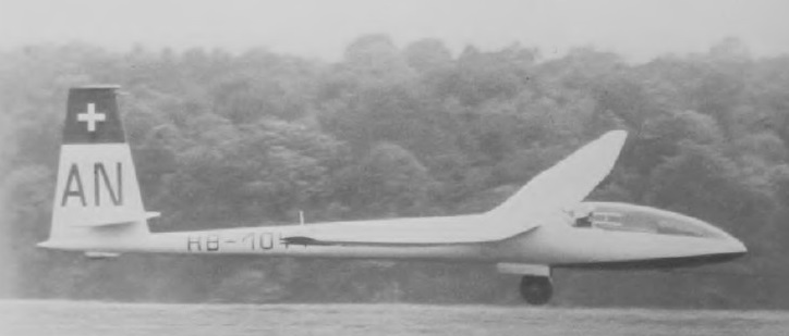
The AN-66D prototype, produced in 1974, has a four-piece wing of 21m (68 ft 11 in) span.
AN-66C Super-EIfe
Span: 75 ft 5.5 in / 23.0 m
Length: 26 ft 6.25 in / 8.1 m
Height: 6 ft 0.75 in / 1.85 m
Wing area: 172.2 sq ft / 16.0 sq.m (flaps in)
Wing section: Eppler 562/569
Aspect ratio: 33.1 (flaps in)
Empty weight: 926 lb / 420 kg
Max weight: 1,433 lb / 650 kg
Water ballast: 60 kg / 132 lb
Max wing loading: 33.1 kg/sq.m / 6.8 lb/sq ft
Max speed: 168 mph / 146 kt / 270 km/h (in smooth air)
Stalling speed: 32.5 kt / 60 km/h
Min sinking speed: 1.64 ft/sec / 0.5 m/sec at 46.5 mph / 40.5 kt / 75 km/h (flaps out)
Best glide ratio: 48:1 at 56 mph / 48.5 kt / 90 km/h (flaps in)
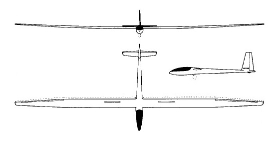
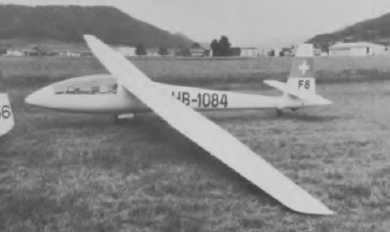
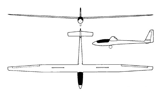
A developed version of the Standard EIfe S-3, the S-4A EIfe 15 differs from it principally in having a new two-piece wing of the same 15m span, strengthened and fitted with Schempp-Hirth air brakes; the single spar is of aluminium alloy and the wing skin of plywood/foam sandwich. A roomier forward fuselage of improved aerodynamic shape is featured, with the slight step forward of the canopy on the Standard EIfe S-3 completely eliminated. The fuselage and tail unit are of glassfibre and plywood/foam sandwich construction, and the landing gear consists of a retractable rubber-sprung monowheel with brake. The prototype EIfe 15 made its first flight in 1970 and 10 had been built by early 1973; production continues, although at a rather slow rate.
Both the EIfe 15 and EIfe 17 were available in kit form for amateur construction, the latter being a 17m span Open Class version of the S-4A EIfe 15, with the same fuselage but with a wider span two-piece wing, with provision for a tank in each leading edge to house a total of 132lb of water ballast. The EIfe 17 also has a braking parachute fitted, and a total of 10 of this version had been built by the spring of 1973, with production continuing at a relatively slow rate.
The EIfe M17 is a single-seat motor glider version of the Open Class EIfe 17 and first flew in prototype form in mid-March 1978. It is powered by a 45hp Parodi HP 45 four-cylinder four-stroke engine driving a Hoffmann two-bladed propeller; this is pylon-mounted aft of the cockpit and retracts into the fuselage when not in use. Electric starting is provided and the fuel tank capacity is 10 Imp gallons (45 litres). Apart from the engine and its related modifications the EIfe M 17 is the same as the unpowered EIfe 17.
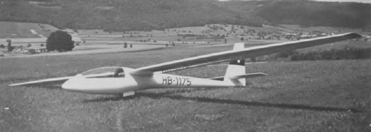
EIfe 17
Span: 55 ft 9.25 in / 17.0 m
Length: 23 ft 3.5 in / 7.1 m
Height: 4 ft 11 in / 1.50 m
Wing area: 142.1 sqft 13.2 sq.m
Wing section: Wortmann FX-61 -163/60-126
Aspect ratio: 21.8
Empty weight: 562 lb / 255 kg
Max weight: 837 lb / 380 kg
Water ballast: 60 kg / 132 lb
Max speed: 130 mph / 113 kt / 210 km/h
Max aero-tow speed: 87 mph
Max rough air speed: 113 kt / 210 km/h
Stalling speed: 35 kt / 65 km/h
Min sinking speed: 1.84 ft/sec / 0.56 m/sec at 46.5 mph / 40.5 kt / 75 km/h
Best glide ratio: 39:1 at 56 mph / 48.5 kt / 90 km/h
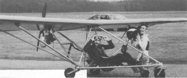
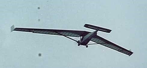
Single seat single engined high wing mono¬plane with conventional three axis control. Wing has unswept leading edge, swept for¬ward trailing edge on outboard half of span, and tapering chord; conventional tail. Pitch control by elevator on tail; yaw control by fin mounted rudder; roll control by half span ailerons; control inputs through stick for pitch/roll and pedals for yaw. Wing braced from below by struts; wing profile NACA 4415; double surface. Undercarriage has three wheels in tricycle formation with addi¬tional tailskid; no suspension on nosewheel and rubber suspension on main wheels. Push right go right nosewheel steering con¬nected to yaw control. Brakes on main wheels. Aluminium tube framework with optional pod. Engine mounted below wing driving pusher propeller.
The AN 22 was designed by the Swiss Albert Neukom who also built the first two examples to obtain certification in West Germany. The AN 22 made its first flights in March 1983 and was shown in the same month at the Aero 83 exhibition at Friedrichshafen. Point Aviation acquired the licence to build and sell this machine throughout the world, the first production machines being built in spring 1983. The model makes use of the original formula tried by Albert Neukorn in 1982 on the prototype AN 20, whereby the three¬cylinder Konig 430 cc engine is carried behind the wing on a mount coming from the large diameter spar which carries the tail. This spar also acts as the axis of the propeller which is driven through a triple V belt reduction drive. The two blades can fold backward parallel to the spar.
Production versions were factory built and sold by Point Aviation in West Germany.
Neukom completed the construction (May 1983) of the AN 22 Twin, a two seater version of the AN 22.
AN-22
Length overall 18.4 ft, 5.60 m
Height overall 4.3ft, 1.30m
Wing span 33.511, 10.20m
Chord at root 3.9ft, 1.20m
Chord at tip 3.3ft, 1.00m
Dihedral 4 degrees
Sweepback 0 degrees
Tailplane span 8.5 ft, 2.60 m
Fin height 3.1 ft, 0.95 m
Total wing area 126 sq.ft,11.8 sq.m
Total aileron area 12.1 sq.ft, 1.12 sq.m
Fin area 6.6 sq.ft, 0.61 sq.m
Tailplane area 11.7sq.ft, 1.09sq.m
Total elevator area 6.5 sq.ft, 0.60sq.m
Wing aspect ratio 8.9/1
Wheel track 6.2 ft, 1.90 m
Nosewheel diameter overall 10 inch, 26cm
Main wheels diameter overall 12 inch, 30 cm
Engine: Konig SC430, 22hp at 4200rpm
Propeller diameter 52 inch, 1.32 m
Belt reduction, ratio 1.8/1
Max static thrust 143 lb, 65 kg
Power per unit area 0.17 hp/sq.ft, 1.9 hp/sq.m
Fuel capacity 5.3 US gal, 4.4 Imp gal, 20.0 litre
Empty weight 232 lb, 105 kg
Max take off weight 464 lb, 210kg
Payload 232 lb, 105kg
Max wing loading 3.68 lb/sq.ft, 17.9 kg/sq.m
Max power loading 21.1 lb/hp, 9.5kg/hp
Load factors +6.0, 3.0 ultimate
Max level speed 75 mph, 120 kph
Never exceed speed 81 mph, 130 kph
Max cruising speed 56 mph, 90 kph
Economic cruising speed 44 mph, 70 kph
Stalling speed 24 mph, 40 kph
Max climb rate at sea level 600 ft/min, 3.1 m/s
Min sink rate 200 ft/min at 32 mph, 1.0 m/s at 52 kph
Best glide ratio with power off 14/1 at 34 mph, 55 kph
Take off distance 330 ft, 100 m
Land¬ing distance 260 ft, 80 m
Range at average cruising speed 124 mile, 200 km
AN-22 Twin
Single seat single engined high wing monoplane with conventional three axis control. Wing has swept forward leading and trailing edges, and tapering chord; no tail, canard wing. Pitch control by elevator on canard; yaw control by tip rudders; roll control by one-third span ailerons; control inputs through stick for pitch/roll and pedals for yaw. Wing braced from below by struts; wing profile Wortmann FX63 137; double surface. Undercarriage has three wheels in tricycle formation; no suspension on nosewheel and glassfibre suspension on main wheels. Push right go right nosewheel steering connected to yaw control. Brakes on nosewheel. Aluminium/tube/fabric fuselage, totally enclosed. Engine mounted at wing height driving pusher propeller.
As Albert Neukorn comfirmed, this machine was never intended for production. In fact, he wanted to design a single seater canard aircraft, as much to try out this formula as for his own pleasure. Of hybrid technology (Duralumin tubular structure with composite materials for the wing, the canard and rudders), the prototype made its first flights in 1980 and remains unique, with no direct descendants. It was originally called the AN 21. Later it was sold to a German purchaser, Klaus-Jurgen Richter, who flew it in the London to Paris in September 1982, and so the aircraft is now called the AN 21R, this last letter referring to Mr Richter himself.
Length overall 16.1 ft, 4.90 m
Height overall 7.9 ft, 2.40 m
Wing span 41.3 ft, 12.60 m
Mean chord 2.8 ft, 0.85 m
Canard span 9.8 ft, 3.00m
Canard chord 1.7ft, 0.53m
Total wing area 132 sq.ft, 12.3 sq.m
Main wing area 115sq.ft, 10.7 sq.m
Canard area 17 sq.ft, 1.61sq.m
Main wing aspect ratio 14.8/1
Engine: Konig SC430, 25 hp at 4200 rpm
Power per unit area 0.19 hp/sq.ft, 2.0 hp/sq.m
Max level speed 81 mph, 130kph
Stalling speed 26mph, 42 kph
Max climb rate at sea level 500 ft/min, 2.5 m/s
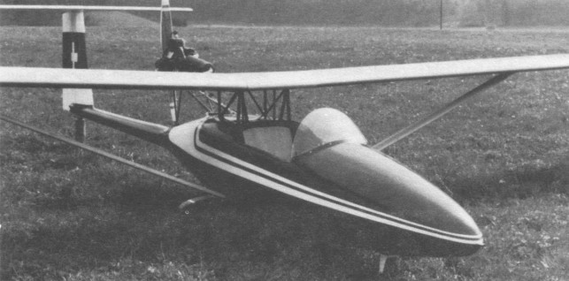
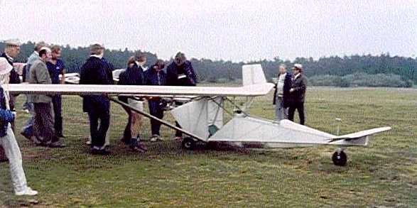
Single seat single engined high wing monoplane with conventional three axis control. Wing has unswept leading and trailing edges, and constant chord; T tail. Pitch control by elevator on tail; yaw control by fin mounted rudder; roll control by one third span ailerons; control inputs through stick for pitch/roll and pedals for yaw. Wing braced from below by struts; wing profile Wortmann FX 63 137; double surface. Undercarriage has three wheels in tricycle formation with tailskid; no suspension on nosewheel and glass fibre suspension on main wheels. Push right go right nosewheel steering connected to yaw control. Brakes on main wheels. Glass fibre fuselage, partially enclosed. Engine mounted at wing height driving pusher propeller. Wing and T tail have wood spars, ribs in styrofoam and covered with expoxied glass fibre.
His first microlight made its first flights in 1978, the prototype AN 20 using a T tail carried on a Kevlar spar of round section. Connected to the fuselage at the same height as the wing, the tubular fuselage carried basically a mono wheel undercarriage but with an additional nosewheel steerable from the rudder bar, the main wheel being positioned directly below the wing. Moreover, the vertical fin below the fuselage spar was provided with a tailwheel in line with the other two.
This machine was shown in various publications under the designation of AN 20M, which was a great surprise to Albert Neukorn, who tells us that he had never called this first model by any other name than AN 20, except that it eventually became AN 20A to distinguish it from the later AN 20B. The prototype was shown at the European homebuilders meeting at Brienne in July 1982.
The AN 20B is directly evolved from its predecessor whose rectangular plan form wing it has retained, supported by a profiled strut under each half wing. A significant change is the inclusion of air brakes, while the AN 20B is provided in addition with an elegant glass fibre fairing with windscreen encompassing all the forward section of the fuselage as far as the trailing edge of the wing, where it joins the spar carrying the tail. Another important difference from the AN-20A is that this spar is no longer level with the wing but mid mounted, a change which required a re design of the T tail. As a result, the fin and rudder no longer continue below the spar. The engine, previously fitted below the spar is now carried by a tubular structure above the rear spar, effectively level with the wing. Production models use the three cylinder Konig SC430 driving a three bladed pusher propeller. Finally, a last important modification, the AN 20B replaced the single main wheel undercarriage of the AN 20A with a tricycle undercarriage whose main wheels are fitted with drum brakes.
The AN 20B was still produced by Albert Newkom himself in 1983, either ready to fly ex works without engine or as a set of plans. An attempt to set up production facility in France with the AN 20B in 1981 has been abandoned.
Length overall 17.7 ft, 5.40 m
Height overall 3.9ft, 1.20m
Wing span 41.3ft, 12.60m
Constant chord 2.611, 0.80m
Dihedral 2 degrees
Sweepback 0 degrees
Tailplane span 8.0ft, 2.45m
Fin height 3.2ft, 0.95m
Total wing area 109sq.ft, 10.1sq.m
Total aileron area 8.5 sq.ft, 0.79 sq.m
Fin area 6.6 sq.ft, 0.61 sq.m
Tailplane area 8.4 sq.ft, 0.78 sq.m
Total elevator area 4.2 sq.ft, 0.39 sq.m
Wing aspect ratio 15.8/1
Wheel track 4.7ft, 1.43m
Nosewheel diameter overall 8 inch, 21 cm
Main wheels diameter overall 8.5 inch, 22cm
Engine: Konig SC430, 24 hp at 4200 rpm
Propeller diameter 42 inch, 1.06 m
Belt reduction, ratio 1.8/1
Max static thrust 121 lb, 55 kg
Power per unit area 0.22 hp/sq.ft, 2.4 hp/sq.m
Fuel capacity 5.3 US gal, 4.4 Imp gal, 20.0 litre
Empty weight 287 lb, 130 kg
Max take off weight 508 lb, 230 kg
Payload 221 lb, 100 kg
Max wing loading 4.68 lb/sq.ft, 22.8 kg/sq.m
Max power loading 21.2 lb/hp, 2.4kg/hp
Load factors; +5.3, 2.6 ultimate
Max level speed 93 mph, 150 kph
Never exceed speed 99 mph, 160 kph
Max cruising speed 68 mph, 110 kph
Economic cruising speed 59 mph, 95 kph
Stalling speed 31 mph, 50 kph
Max climb rate at sea level 500 ft/min, 2.5 m/s
Min sink rate 160 ft/min at 37 mph, 0.80 m/s at 60 kph
Best glide ratio with power off 18/1 at 37 mph, 60 kph
Take off distance 360 ft, 110 m
Land¬ing distance 330 ft, 100m
Service ceiling 11,500 ft, 3500 m
Range at average cruising speed 186 mile, 300km
A single-seat homebuilt aircraft.

The Elfe series started from a 9 m sailplane designed by W.Pfenninger before World War II. Just after World War 2 Albert Neukom of Switzerland began the creation of a line of sailplanes bearing the name EIfe; the first of these, the EIfe 1, had a wing span of only 9m (29 ft 6.25 in), later increased to 11m (36 ft 1 in).
A new design was introduced in 1947 to become the Elfe 2, probably the first sailplane with a laminar flow airfoil. The EIfe 2, with a span of 50ft 6.25in, had camber-changing flaps.
Subsequently the series was further developed by Albert Neukom with the Elfe M with laminar flow wings, Elfe MN and AN66 before the Standard Elfe S-1 appeared in 1964 with a V-tail. The prototype high performance single-seater Standard EIfe S-1 first flew on 1 May 1964. This was followed by the S-2 with conventional tail with the tailplane at the base of the fin.
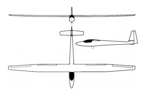
The S-3, the production model of the S-2, first flew in May 1966 with a tailplane fixed part of the way up the fin. It has trailing edge airbrakes and a rubber- sprung retractable main wheel. The EIfe S-3 has a high cantilever wing built in three parts, and of plywood-balsa sandwich construction; it is fitted with trailing edge air brakes. The fuselage and tail unit are of glassfibre and plywood sandwich construction, while the landing gear consists of a retractable rubber-sprung monowheel with brake. The pilot sits upright under a removable transparent canopy.
Flown by the Swiss plot Markus Ritzi, a Standard EIfe took 2nd place in its class at the 1965 World Gliding Championships held at South Cerney, and at the 1968 World Championships at Leszno in Poland a Standard EIfe S-3 flown by Andrew Smith of the USA came 1st out of 57 entries, with other Elfes placed 4th and 6th.
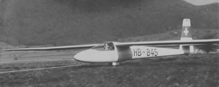
A total of 18 Standard Elfes were flying by April 1970, the year in which the developed S-4A EIfe 15 first flew.
Standard EIfe S-3
Wing span: 15 m / 49 ft 2.5 in
Wing area: 11.9 sq.m / 128.1 sq.ft
Wing section: Wortmann FX Series
Length: 7.30 m / 23 ft 1.5 in
Height: 1.50m / 4 ft 11 in
Empty Weight: 208 kg / 459 lb
Payload: 112 kg / 246 lb
Gross Weight: 320 kg / 705 lb
Water ballast: None
Wing Load: 26.89 kg/sq.m / 6.79 lb/sq.ft
Aspect ratio: 19
L/D Max: 37.5 @ 95 kph / 51 kt / 59 mph
Min Sink: 0.64 m/s / 2.1 fps / 1.24 kt at 47 mph / 40 kt / 74 km/h
Max speed: 150 mph / 129.5 kt / 240 km/h (in smooth air)
Max rough air speed: 108 kt / 200 km/h
Stalling speed: 30 kt / 55 km/h
No. of Seats: 1
Structure: Balsa/ plywood sandwich wing; glass fibre/ plywood sandwich fuselage
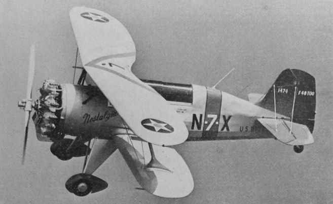
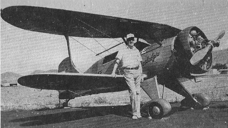
In 1974 Wil Neubert built the Neubert Nostalgia N7X, Stolp Starduster Too variation. A two place cabin biplane powered by a 220hp Continental, it was seriously modified to resemble a USN Boeing F4B.
Long Beach CA
San Luis Obispo CA.
USA
In 1974 Wil Neubert built the Neubert Nostalgia Stolp Starduster Too variation.

