During the early 1970s, RAF pilot Jeffery Siers designed and personally built the first Barracuda. When completed, he took it to Oshkosh 1976 where it won Best New Design. While building it, Siers would finish a set of plans and material list, and send them to Bill and Marilyn Buethe would would then build the component and send back suggestions for improvement. In January 1981, Bill Buethe and his Barracuda flew. Bill and Marilyn bought the airplane rights from the designer, Jeff Siers and under the name Buethe Enterprises, they sell plans, information kits, canopies, cowlings, and engine mounts. Plans were selling for US$200. A 200 mph two-seater, the Barracuda, made entirely of spruce and plywood, is a fast, high performance, side by side two place with retractable, tricycle gear. Rated for limited acrobatics, it has a 200 MPH cruise speed and 2,100 FPM rate of climb with a Lycoming O540 Engine. Power may vary from 200 to 300 horsepower. A stall speed of 62 makes landing easy. The comfortable 40 inch wide cockpit, with the sound deadening properties of wood, makes it a wonderful cross-country tourer. The structure is elegant and simple, like a model airplane, with no complex jigging.
Engine: Lycoming IO-540, 250 hp Wing span: 24 ft 9 in Wing area: 120 sq.ft Length; 21 ft 6 in Max ramp weight; 2300 lb MTOW: 2300 lb Max landing weight: 2300 lb Empty weight: 1500 lb Useful load; 800 lb Wing loading: 19.17 lb/sq.ft Power loading: 9.2 lb/hp Fuel capacity; 44 USG Cruise, max pwr 7000ft: 200 mph Stall clean: 64 mph Stall flaps down: 62 mph ROC: 2000 fpm Service ceiling: 18,000 ft Takeoff roll: 800 ft Landing roll; 1000 ft Landing gear; tri retractable Seats: 2 Wheels/tires: 5.00×5 or 6.00×6
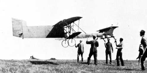
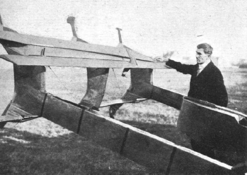
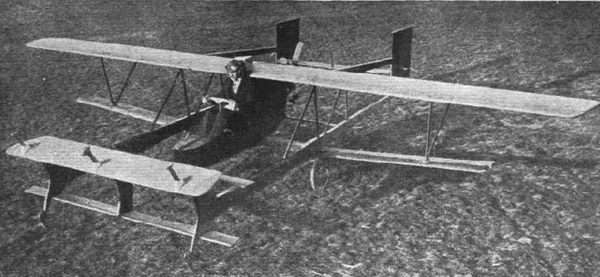
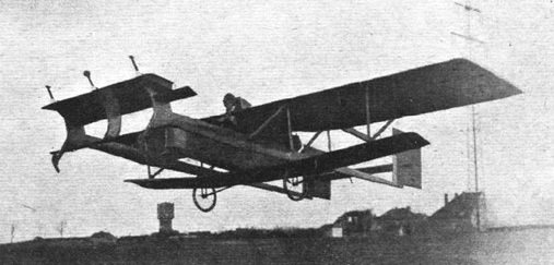
Among the machines entered in the Rhön competition in Germany in 1921 was a canard-type glider, designed and built by Friedrich W. Budig. It is a sesquiplan: in fact, the lower wing is of smaller span and chord than the main wing. The canard stabilizer in the front, in two parts: the main part serving for automatic longitudinal stabilization, and behind the latter, a conventional flap for controlling the attitude, actuated by the pilot. On both versions, there is also a horizontal plane at the rear, of very small surface, which seems to be fixed.
The machine featured an original automatic device for controlling the pitch stability.
Budig shows the flexible device described in the patent.
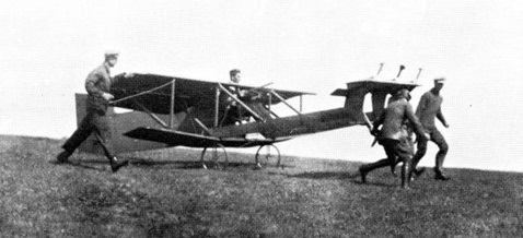
At the beginning of 1923, Flight International published an article which re-spoke of the machine of F. Budig, in a new version, with a fuselage deeply modified in its rear part, in order to install a motor there. It was a BMW flat-twin motorcycle engine developing 4 hp. The propeller being mounted in direct engagement with the motor.
It seems that the power developed by the engine was not sufficient to allow a take-off of the machine without assistance of a catapult. Once in the air the machine had to be able to fly horizontally, or at best to climb with a low rate of climb. The motorization was only allowed to prolong the flight somewhat.
The motorized version at Wasserkuppe 1923
In May 1924 there was the second Rossiten-free flying contest near Koenigsberg (West Prussia). This contest was a landmark in the history of gliding, as it saw the world record of duration extended to 8 hours 42 minutes 9 seconds by Ferdinand Schultz with his FS-3 Besenstiel (May 11, 1924). Hentzen and Budig participated in the contest and both announced that they intended to purchase a Blackburne engine to equip their respective gliders.
Budig replaced the initial BMW with a Salmson A.D. 3. This engine, manufactured by the Salmson Motors Company, Billancourt, France, of a little less than 1000 cc displacement, developed 12 CV (18 kW) at 1800 rpm and weighs 34 kilograms.
This engine proved its worth in the 1920s by winning the Grand Prix de la Moto-Aviette and the Prix Solex (in 1925).
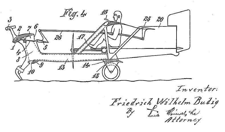
Extract from the patent, a drawing in side view of a machine proposed by F. Budig.
F.W. BUDIG Flying machine Application filed June 16, 1921
1,419,447 Patented June 13, 1922
To all who it may concern: Be it known that I, FRIEDRICH WILHELM BUDIG, citizen of the state of Prussia, residing at Falkenberg-Grunau, near Berlin, in the state of Prussia, Germany, have invented certain new and useful Improvements in Flying Machines (for which I have filed applications in France, Aug. 1, 1914, and in Germany Jan. 29, 1920 and Nov. 20, 1920), of which the following is a specification. This invention relates to a steadying device. It consists in the combination of the supporting planes with an adjustable steadying plane. This later plane is rotatably supported on an axle supported in its turn by the flying machine, and its forms, together with an immovable surface with which it is connected, preferably by bellows, a hollow space within a depression may be produced in known manner by the mediation of a surface feeler. The steadying plane is adjusted to various inclinations by which depression, contrary to the action of a spring. Besides these arrangements, the present invention also relates to means for correctly adjusting the steadying plane, as is particularly necessary for soaring flying apparatus.
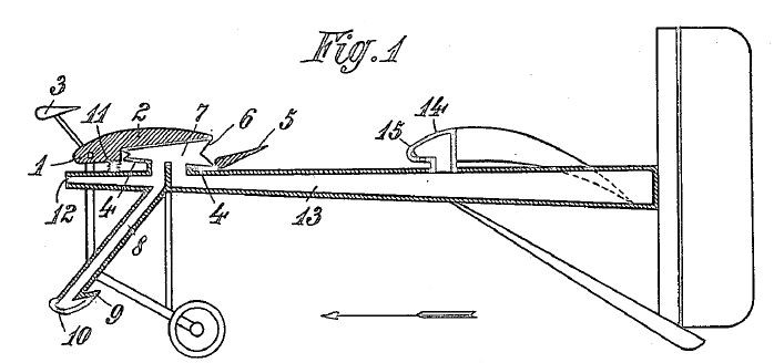
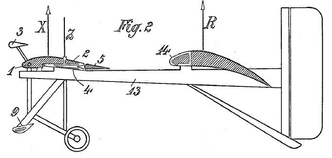
Reffering to the accompanying drawing, Figure 1 is a vertical section through a motorized flying machine with a novel device in question being shown in the position it occupies at too slow flight; Figure 2 is a side-view of the machine, only some upper parts (2, 5, 14) in section, and the position of the automatic steadying being that it occupies at normal speed; Figure 3 is a diagrammatic illustration of the succession of the swing motions of the machine; and Figure 4 is a side view of a soaring flying machine having a small auxiliary motor. The upper body 2 of the steadying plane is hinged to a horizontal axle 1 firmly supported by the frame of the flying machine. Affixed to said body 2 is a counterpoise 3, the arrangement being that the total center of gravity of the poise and the body 2 is located above the common axis of rotation the law of inertia initiates a favorable swinging or turn of the upper body 2. Parallel with the body 2, and having the same breath as this body, is an immovable flat 4, to the rear of which is hinged the horizontal rudder 5 for altitude steering. The body 2 and the plate 4 are connected with each other by bellows 6 forming or enclosing a chamber 7 which communicates by a channel or passage 8 with the hollow feeler plane 9 which has the shape of an inverted supporting and is provided with a slot 10 extending over the whole of its breadth. 11 is a spring which tends to turn the body upwards about the axle 1, that is to say, to expand the bellows. The position of the parts 2 and 6, if no partial vacuum within the bellows counteracts the spring, is that shown in Figure 1. The bellows communicates with the atmosphere not only through the channel 8, but also through an aperture 12 which is at the front of the machine and constantly open. The sectional area of the aperture 12 is smaller than that of the slot 10. The supply of the air through the aperture 12 does not materially affect the degree of rarefaction in the bellows as long as the air entering through that aperture flows off through said slot, as in the case during flying with normal speed. But if the speed decreases, the body 2 can rise, under the pressure of the spring 11, far more quickly than would be the case if no supply of air through the aperture 12 would take place, because, as is known by experience, air, even at reduced speed, can enter only with great difficulty through the slot 10 into the bellows.
In order to accelerate the swinging movement of the body 2 in the direction to the plate 4 at an increase of the speed of flight, the space 7 is connected by one or more air-channels 13 provided in rigid parts of the structure preferably tubes, and forming a kind of girder with the spaces of hollow bodies 14 united with the main supporting planes. The tubes 13, or their equivalents, carry the above described combination and arrangement of parts and serve also for fastening the means provides for the landing. The hollow body 14 forms a rigid piece for and of the supporting plane and its front portion the blowing-at edge of said plane. The supporting wall of that body 14 differs from an ordinary hollow supporting plane chiefly by a slot 15 which is provided in the lower surface of the projecting front part of the body 14, similarly to the slot 10, and the length of which is about one fourth of the length of the slot 10, provided, that the machine has an aperture such as 12. By measurements it is known that at that place of the supporting frame profile where the slot 15 is located a strong depression is produced at quick flight. This observation confirms that at slow flight the slot 15 assists the action of the aperture 12, and at quick flight assists the action of the slot 10.
Thus, if the angle of incidence at which the flight takes place is reduced, then, by the addition of the slot length 15 with the slot length10, a certain definite amount of air to be sucked out of the bellows space 7 is exhausted more quickly and the body 2 moves correspondingly quicker in the direction of the plate4 ; that could not be the case without the slot 15.The manner in which the body 2 is turned in the one or the other direction will become clear from a description dealing with flying in soaring manner, as follows : Supposing the machine be soaring motionless in a constant head-wind under a large angle of incidence. In this case the lifting power R acts at the main supporting plane, and the lifting power X acts at the steadying surface. The lifting power of the horizontal rudder 5 which latter is controlled by the hand of the pilot, and the buoyancy of the stationary plate 4 may be neglected in these considerations because said two influences approximately compensate the downwardly directed power of the receptacle 9. Besides the lifting power X, also the power of the spring 11 acts upon the body 2, in the same direction as said power X, and, furthermore, also the suction power Z which is produced in the space 7 by the depression and acts in the opposite direction. These three powers balance each other at normal flight and determine the profile of the steadying surface, as illustrated in Figure 2. Now, if the wind relatively to the flying machine, suddenly grows stronger owing to a squall or gust, then also the powers X and R increase at the same time. Although also the suction power at the slot 10 becomes greater at the same time, still, the power Z does not immediately vary because the amount of air to be led away is increased by the supply of air taking place through the aperture 12 and 15. Besides, the increased suction power at the slot 12 which tends to increase the power Z is opposed by three other powers. Firstly, the increased lifting power X tends to turn the body 2 upwards which is made possible only by air entering through the apertures 12 and 15. Secondly, the flying machine is, at the commencement of the squall or gust, at first shoved backward by reason of the additional resistance, in consequence of which the high-lying center of gravity of the body 2 and the poise 3 swing forward by reason of their inertia ; thirdly, this latter cause makes the air present within the channel 13 move in the direction to the space 7. A sudden increase of the lifting power X by an outer wind power causes, thus, the body 2 to swing upwards, whereby the additional buoyancy at the front of the machine is made ineffective.
Matters are different with the rigid main supporting surface at which the power R has been increased. The diagram of forces (Figure 3) shows that the front of the machine has remained at the point C, owing to the annihilation of the addition to the power X, whereas the main supporting plane ascends from A to B. The swinging motion in forward direction occurring at the rear part of the machine being lifted entails forward drive, whereby the speed of the machine is increased and, also a variation in the play of forces at the steadying devicer is brought about. As the angle of incidence at the main supporting plane has become smaller by reason of the additional upward motion, suction takes place at the slot 15, and as also the opposing forces that acted upon the body 2 do no more exist, this latter is turned in the direction of the plate 4 whereby the buoyancy at the front of the machine is increased and this latter rises from the position C to the position D.
From both successively occurring motions of the flying machine results that this latter is rising for the height H without a loss of speed.In the practical application of the arrangement in question a greater measure than the length C-A which is chosen only by way of example will be given the radius of oscillation; that may be easily attained by only partially annihilating, by the means stated, the power increased by the squall or gust. Owing to its dimension, the rear rim of the movable body 2 forms for the pilot a readily visible indicator of the conditions of motions of the flying machine. The pilot may at his discretion either promote the indications of the rear rim or edge of the body 2 by appropriately operating the horizontal rudder or oppose them, also by appropriately actuating said rudder, for instance at landing. The flying machines with but slight load per unit of surface are easily overturned by wind after the landing. The soaring flying machines shown in Figure 4 is so constructedthat the wind cannot lift its front part off the ground because an aperture is provided which is kept closed during the flight by a flap 16, but permits of a large supply of air through the channel 17 if it is open, so that the steadying plane is ensured against being drawn against the plate 4. In testimony whereof I have affixed my signature in the presence of two witnesses. FRIEDRICH WHILHELM BUDIG Witnesses: FRANGE SURNAM and EMIL VORWERK.
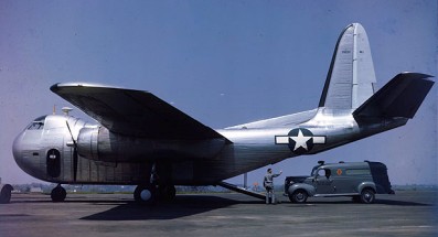
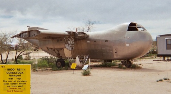
World War II created a great demand for military transport aircraft in the United States. Because of initial fears of a shortage of aluminum, the War Department explored the use of other materials for aircraft construction. Budd, the developer of the shotweld technique for welding stainless steel and a manufacturer of stainless steel railroad cars, automobile, bus, and truck bodies, hired an aeronautical engineering staff and worked with the U. S. Navy to develop a new twin-engine transport aircraft constructed primarily of stainless steel. The U.S. Navy accepted the proposal for the new aircraft, and placed an order for 200, to be designated RB-1. The U.S. Army Air Forces (USAAF) followed with an order for 600, designated C-93.
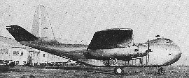
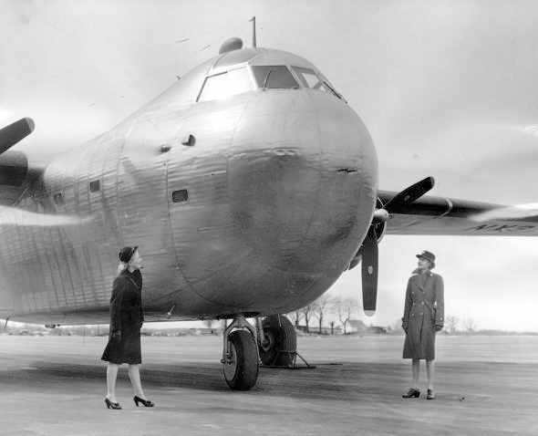
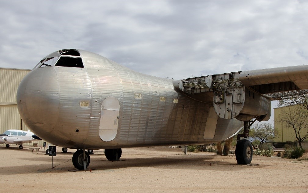
The Conestoga was a twin-engine high-wing monoplane with tricycle landing gear. The elevated flight deck was contained in a distinctive, almost hemispherical nose section. Its two 1,200 hp (890 kW) Pratt & Whitney R-1830-92 air cooled 14-cylinder, twin-row, radial engines, the same engines fitted to the C-47, drove three-bladed Hamilton Standard Hydromatic constant-speed, full-feathering propellers and powered a 24-volt electrical system. While the fuselage was thin-gauge stainless steel, only a portion of the wing was made of the metal; the trailing section of the wing and all control surfaces were fabric-covered.
The RB-1/C-93 introduced many of the features now standard in military transports. The flight deck could accommodate three crew members, pilot and co-pilot side-by-side, the navigator behind them. Stairs connected the flight deck to the cargo area, which was 25 feet (7.6 m) long with an unobstructed cross-section of 8 × 8 feet (2.4m) throughout its length.
Cargo loading and unloading could be accomplished in two ways: through 40 × 60 inch (102 × 152 cm) doors on both sides of the fuselage or by an electrically operated 10 × 8 foot (3.0 × 2.4 m) ramp at the aft end of the cargo area under the upswept tail, a similar development to what had been initially fitted to the Germans’ own Ju 90 four-engined transport aircraft as their Trapoklappe ramp in 1939.
The RB-1’s loading ramp, accessed by manually operated clamshell doors, along with the tricycle landing gear, meant cargo could be loaded/unloaded at truck-bed height. A manually operated two-ton (907 kg) hoist for unloading trucks and a one-ton winch for pulling cargo up the ramp were also provided in the cargo area. The aircraft could accommodate: 24 paratroopers, or 24 stretchers and 16 sitting wounded, or 9,600 pounds of cargo, or a 1½ ton truck, or The RB-1 could carry 9,600 pounds of payload, in addition to 390 US gallons of fuel.
The largest ambulance in use by the U.S. military.
The prototype first flew from the Budd Red Lion Factory Airfield in Philadelphia, Pennsylvania on 31 October 1943, piloted by Guy Miller. The prototype had a takeoff run when empty of just 650 feet (200 m), and could carry a maximum payload of 10,400 pounds (4,700 kg) with a takeoff run of 920 feet (280 m). However, the aircraft demonstrated greater than expected fuel consumption; the range with a standard payload was only 700 miles (1,100 km), 650 miles (1,050 km) with a maximum payload.
Three prototype aircraft: NX37097, NX41810, and NC45354 were built; one was used for testing radio equipment, while the other two were used for flight test evaluations. During testing, a few aircraft had difficulty with the simultaneous deployment of the right and left landing gear. With the same engines as the C-47, but 3,000 pounds (1,400 kg) heavier (empty), the aircraft was relatively underpowered.
At the Budd factory and airfield in Philadelphia, Pennsylvania, there were construction delays due to cost overruns and problems with stainless steel fabrication. By late 1943, aluminum production had been increased with the construction of new processing facilities, and other more conventional cargo aircraft (such as the Curtiss C-46 Commando and the Douglas C-47 Skytrain) were being produced in large numbers. This caused the Army to cancel its order for the C-93 and the Navy to reduce its RB-1 order from 200 to 25, of which 17 were delivered in March 1944.
On 13 April 1944, during a Naval Air Training Command (NATC) evaluation flight of RB-1 prototype U.S. Navy NX37097 at Patuxent River NAS, Maryland, the aircraft crashed, killing one of the crew. The aircraft was damaged beyond repair and written off, but the pilot reported that the stainless steel construction of the aircraft contributed to saving his life.
Production RB-1 aircraft never entered squadron service with the Navy, but a few were briefly used by Naval Air Stations as utility aircraft. With only 17 aircraft in inventory, the RB-1 was not feasible to maintain on the active list, and it was retired from U.S. Navy service in early 1945.
The extant RB-1s were then transferred to the War Assets Administration (WAA) to be sold as war surplus. In 1945, the WAA sold 12 Conestogas to the National Skyway Freight Corp for $28,642 each. The new company, founded by members of the AVG Flying Tigers immediately sold four RB-1 aircraft to other buyers, which paid for the entire WAA contract.
The seven remaining National Skyways aircraft were used to transport a variety of cargo, shipping fruit and furniture from its base in Long Beach, California. Pilots reported that the Budd transports were temperamental; in particular, exhaust stacks kept falling off and causing engine fires. There were three more crashes of Conestogas while in service with National Skyway Freight, one each in Virginia, New Mexico, and Michigan. The crash in Virginia was a belly landing at a country club brought on by fuel exhaustion following weather-related problems. The Albuquerque, New Mexico crash was due to a downdraft during a snow storm, 80 miles (130 km) from Albuquerque. Pilot and co-pilot were killed when they were thrown through the windshield and the aircraft skidded over them; the flight engineer survived.
In 1947, the U.S. Army (and later the U.S. Air Force) gave National Skyway Freight a large contract for trans-Pacific freight, for which it leased military aircraft. The company changed its name to Flying Tiger and replaced the RB-1s with C-47s for its U.S. freight routes; the RB-1s were sold off to other buyers. One of these aircraft, a prototype RB-1, “NC45354” was sold to the Tucker Motor Company to transport its demonstration 1948 Tucker Sedan to auto shows around the U.S.; it was reportedly later abandoned at an airfield in Oakland, California after repeated mechanical troubles.
In Brasil, Viação Aérea Santos Dumont started with the purchase of two Catalinas and a Budd Conestoga, both former Rubber development Corporation. The RB.1, registered PP-SDC “Tio Sam” was damaged in an emergency landing at Campo dos Afonsos on 04.01.1947, landing on one engine, declared unrecoverable and there scrapped.
A single unrestored Budd RB-1 BuNo 39307 is on display at the Pima Air & Space Museum in Tucson, Arizona.
RB-1 Engines: 2 × Pratt & Whitney R-1830-92, 1200 hp (890 kW) each Wingspan: 100 ft 0 in (30.48 m) Wing area: 1,400 ft2 (130.06 m2) Length: 68 ft 0 in (20.73 m) Height: 31 ft 9 in (9.68 m) Empty weight: 20156 lb (9143 kg) Gross weight: 33860 lb (15359 kg) Maximum speed: 197 mph (317 km/h) Cruise speed: 165 mph (266 km/h) Range: 700 miles (1127 km) Crew: 2 Capacity: 24
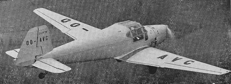
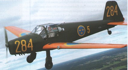
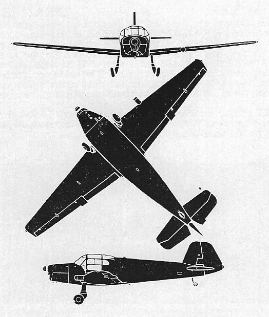
The Bu 181 low-wing monoplane trainer was a development of the Bu 180 Student with enclosed side-by-side accommodation for the crew of two and typical mixed construction (ply/fabric-covered wooden flying surfaces, aluminium alloy covered steel tube forward fuselage and wooden monocoque rear fuselage) with fixed tailwheel landing gear.
The production version for the Luftwaffe was the Bu 181A of which several thousand were built in Germany. Production was transferred to Fokker in Holland (who produced nearly 1000) and Zlin in Czechoslovakia. More production was undertaken in Holland (708) and Sweden by Hägglunds & Söner (125 Sk 25s) during 1944-46 for the Flygvapnet.
Post-war production was launched in Czechoslovakia as the C.6 and CC.106 (105 hp Minor 4-III) and, in civil form as the Zlin 381.
Zlin 381
Under Czech license, the Bu 181 was built Egypt as the ‘Republic of Egypt’, and one civil machine was designated Gomhouria Mk.2.
The final war-time development was the Bu 181D with a number of detail improvements over the Bu 181A. In addition to its designed role, the Bu 181 was used as a communications aeroplane and, in small numbers, as a tug for light training gliders.
Heliopolis Air Works in Egypt was formed 1950 to manufacture a local version of the German Bücker Bu 181D Bestmann as the Gomhouria trainer for Egypt, Jordan, Libya, Saudi Arabia, Somalia and the Sudan.
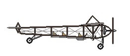
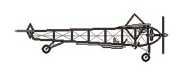
Brothers Wincent and Rudolf Schindler, wealthy millers from Kraków, built in 1908 a working model airplane and in 1910 they commissioned a talented engineer Henryk Brzeski to build a plane to their ideas, named Aquila (Latin for “eagle”). In August 1910 it was demonstrated on the ground to emperor Franz-Josef I, and several days later a test-flight attempt was made, during which it crashed into a fence at the outskirst of the airfield.
Initial configuration
Final configuration
Span: 32’10” Length: 32’10” Weight empty: 660 lb pilot and 2 passengers
The Freedom 28 won Grand Champion Reserve at Oshkosh 1986 and was still available in 1996. The airframe is all aluminium sheet metal with a steel undercarriage.
Top speed: 86 mph Cruise: 76 mph Stall: 27 mph Range: 138 sm Rate of climb: 950 fpm Takeoff dist: 150 ft Landing dist: 150 ft Service ceiling: 20,500 ft Engine: Hirth 2702, 40 hp HP range: 28-42 hp Fuel capacity: 5 USG Empty weight: 310 lb Gross weight: 560 lb Height: 6 ft Length: 18 ft Wing span: 28 ft Wing area: 112 sq.ft Seats: 1 Landing gear: tailwheel
The LF-1 was designed by Prof. Dr.-Ing. Hermann Winter and some of his students from the Technische Universität Braunschweig (English:Technical University of Brunswick), Lower Saxony, Germany in 1939, as a fool-proof trainer for novice student pilots to experience solo flight. Winter was a former chief engineer at the Bulgarian company, DAR (Drzhavnata Aeroplanna Rabotilnitsa in cyrillic ДАР – Държавната аеропланна работилница).
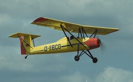
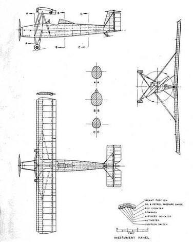
The LF-1 is a parasol wing monoplane with a high-set tailplane, powered by a Zündapp Z 9-092 engine delivering 37 kW (50 hp), able to operate from a 100 m (330 ft) airstrip. The two-piece wings are set at 16° dihedral and are supported by a pair of v cabane struts and v-struts either side from approx half-span to the lower centre fuselage. Full span leading edge slats extend automatically and full span trailing edge flaps / drooping ailerons can be extended manually by the pilot. The fixed tailwheel undercarriage attaches to the fuselage with long struts and oleo pneumatic shock absorbers.
When the flaps were lowered (max. angle 40°), the ailerons also drooped. The Zündapp engine was an air-cooled 4-cylinder engine with single ignition, it produced 51 hp producing a max. airspeed of 87 m.p.h.
It was a proof-of-concept design for a ‘fool-proof’ trainer intended for novice pilots with only one hour of ground instruction, the hour being reduced to five-minutes for those who had already flown gliders, and was intended to be impossible to either stall or spin.
The first prototype, the LF-1 V1, was built in 1940 and made its maiden flight, piloted by Winter himself, on 17 December 1940 powered by a 51 hp Zündapp 9-092 engine. The flight characteristics revealed a good-natured behavior, while the flight performance confirmed the expectations with a stall speed of 29.2 mph (47 kmh) and a maximum speed in level flight of 87.6 mph (141 kmh). The aircraft was repaired and flown again on July 16, 1941, however, on September 11, 1942, during a flight to determine the roll speed of the aircraft, a second serious accident occurred. During the flight tests, performed by the assistant Franz Glatz, there was an overload of the lateral control system, which then failed. This led to the flapping of the wings and subsequently the loss of the right wing. The pilot managed to parachute to safety, the plane crashed onto a truck parked on the parade ground in Brunswick, and both the aircraft and the truck were a total loss.
In 1943 a second prototype, the V2, was built, again receiving the registration D-YBAR. The aircraft was tested for military applications and was once even armed with a Panzerfaust 100 recoilless anti-tank weapon.
The type was named Zaunkönig (Wren) on February 5, 1944.
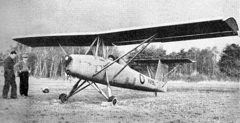
The aircraft survived WW II, but shortly before the occupation of the Technische Hochschule Braunschweig by Allied troops in April 1945, all aircraft documentation was destroyed. In 1945 groups of specialist units were capturing German secrets and technology. Eric ‘Winkle’ Brown led a British aviation team and managed to fly most of the Luftwaffe’s aeroplanes, from the Messerschmitt 163 rocket fighter to the Blohm und Voss 222 6- engined flying boat. One less exotic type he encountered was the Zaunkönig (Wren). An example was brought back to England for thorough testing.
The Zaunkönig registration D-YBAR was taken to the Royal Aircraft Establishment (RAE) at Farnborough for slow flying tests; given the British serial VX190, where amongst others, it was flown by Eric “Winkle” Brown CO Aero Flight, the aircraft also being soloed by the then-head of the RAE Aerodynamics Section, Handel Davies, whose previous experience was as a pupil in a dual-control Miles Magister, after a half-hour of ground instruction.
Most of the pilots found flying the Zaunkönig ‘an interesting experience’. Getting into the small cockpit close under the wing was quite a gymnastic manoeuvre. The engine started easily and with no ignition check or elevator trimmer it was soon time for take-off. The briefing was that flap position was ‘anywhere you like’ and on opening the throttle the aircraft ‘cannot fail to fly itself away’. It left the ground at 44 m.p.h. flaps up or 31 m.p.h. flaps down. The lack of trimmer was not a problem as all three controls were light and pleasantly balanced. Approach to land was at 45 m.p.h. flaps up or 40 m.p.h. flaps down. There was no need to flatten out. The aircraft approached in a three point attitude and the pilot could be told to ‘wait until the ground hits the aircraft’. The undercarriage was strengthened to allow it to absorb the shock of the widest range of landing techniques – or should that be lack of technique.
‘Stalling’ tests were carried out with wool tufts attached to the upper surface of the wing. These were filmed from a following helicopter and showed that, at about 30 m.p.h., engine off or engine on, the centre section of the wing stalled but the outer section went on flying and the ailerons continued to give full lateral control. The Zaunkönig effectively ‘turned into a parachute’.
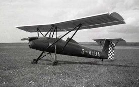
After being wrung out at Farnborough, there seemed to be no useful military function for the Zaunkönig and it was tested by the Civil Aviation Flying Unit of the Ministry of Civil Aviation at Gatwick. There were ideas of using it to promote the expected surge in private flying so it was sold to a British private owner in June 1949 as G-ALUA, and then to the Experimental Flying Group and to the Ultra Light Aircraft Association.
It toured the flying clubs whose members could fly it for £1 per hour. However, it caused little excitement and passed through the hands of several private owners including one in Ireland. At one stage, it was rebuilt by John Isaacs (noted for his own designs of a mini Hawker Fury biplane and mini Spitfire).
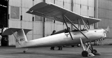
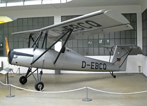
It was subsequently sold in 1974 to an Irish owner, being registered EI-AYU, returning to Germany, in 1976, as D-EBCQ. As of 2008, it was preserved in the Deutsches Museum collection at Oberschleissheim near Munich.
The second Zaunkönig D-EBCQ preserved in the Deutsches Museum, Oberschleissheim, in July 2008
Encouraged by the positive British reviews Prof. Ing. Hermann Winter decided to build a third LF-1. The construction started in 1954 and it was the first new aircraft in Germany after the war to receive a certificate by the Luftfahrt-Bundesamt (LBA) in Braunschweig and the registration D-EBAR. Winter envisioned the Zaunkönig as a People’s Aircraft affordable for all (for a price of around DM 6,000). On 28 April 1957, the wartime Luftwaffe fighter ace Heinrich Bär was conducting a routine flight check in the D-EBAR. Bär put the aircraft into a flat spin, the final manoeuvre in the test process at Braunschweig-Waggum. The aircraft spun down to 50 m (160 ft) then, unable to regain control, it crashed and Bär received fatal head injuries. The aircraft was damaged beyond repair and written off.
At the time a fourth LF-1 V4 was already under construction and it flew a few months after the fatal accident with the V3, in the summer of 1957. It received its certificate in 1958, it expired on October 8, 1964, when the aircraft was grounded, and the code D-ECER. This aircraft flew for some years in Germany until grounded after the death of Prof. Ing. Winter in 1968. In November 1979 it was registered again, this time as D-EBCG, restored in 1980 and flew until 1999 as D-EBCG. The registration was cancelled on October 15, 1999. As of 2008 it was preserved in the collection of the Internationals Luftfahrtmuseum Manfred Pflumm near Villingen-Schwenningen.