The H XII was a light side by side two seater with a 100 hp engine. It was intended as a private owners coupe but R.L.M. were interested in it as a trainer. The first of the type was built and flown at Gottingen (where it was found destroyed in June this year) as a glider; work was also in progress at Kirtorf (sp.) where a mock up of the power center section was found, badly damaged by fire. The wing used a Mustang section at the root graded to a symmetrical section with Mustang fairing shape at the tip. Washout was 3 – 3.5 degrees. Elevon controls were of H VII type with a 20% Frise nose. Plain flaps were fitted with a H IX center section spoiler and “trafficator” drag rudders. The undercarriage was unusual in having two wheels forward and one main wheel aft taking 60% of the weight. All three wheels were retractable. Little flying had been done, but it was found that the same troubles were arising as on the H IVb. The laminar flow sections were causing bad tip stalling and loss of control effectiveness at the stall.
Span: 10 m Aspect Ratio: 8 Wing Area: 32 sp./m (345 sp.ft.) Leading Edge Sweepback: 30 deg Weight: 700 kg (1,550 lb.) Wing Loading: 2.19 kg/sq.in. (4.5 lb/sq.ft.)
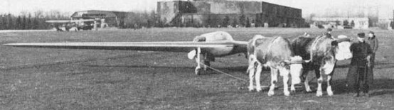
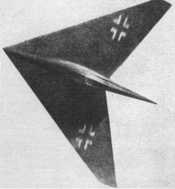
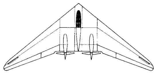
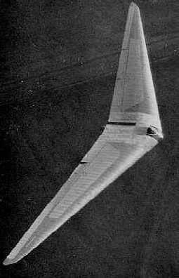
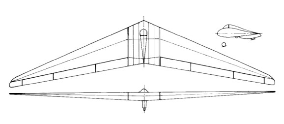
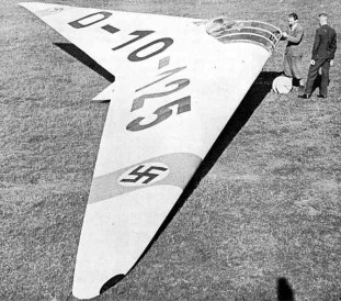
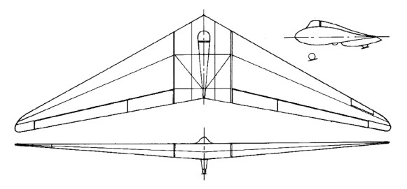
The H X was a high speed arrow shaped flying wing inspired by Busemann’s statement in 1936 of the beneficial effect of sweepback on delay of the shock stall. This apparently cheered up the Horten brothers and gave them new proof that they were working on the right lines. Initial work on the H X consisted of experiments with flying models of 10 ft length weighing about 8-10 kg. From these they deduced the CG position needed for satisfactory flight with low aspect ratio and high sweepback, and found that they got good results with 4 degree dihedral and no fin area. The next step was a man carrying glider model weighing 400 kg. The wing section was a symmetrical D.V.L. low drag type with maximum thickness at 45% chord. Wing washout was 12 degrees, dihedral 4 degree. Small Frise nose elevons were fitted but no flaps; a trimmed CLmax of 0.8 was expected with a stalling incidence of 20 – 25 degrees. Rudder control was to be by wing tip “trafficators”. The undercarriage was of tricycle layout giving zero ground incidence but clearance for a 15 degree nose up attitude at takeoff; the front wheel was to be retractable but the rear wheels fixed.
Work on the glider H X was in progress at Hersfeld. On June 4, 1945 it was being used as an M.T. servicing depot and all aircraft components had been dumped in a basement. Only one wing rib and the main spar could be found. All drawings and calculations had gone. After an exploration of low speed control problems on the glider, the next step was to have been a power version with an Argus AS 10C pusher engine. The final development was envisioned as a jet propelled aircraft, with the same general dimensions, weighing 6-7,000 kg. A single H 11 jet engine was proposed and a top speed of 1,200 kph was expected with 1,300 kg thrust; the thrust was to be improved to 1,500 kg. Initial tests on control effectiveness with high sweep were carried out on the H XIII to guide the control design for the H X. No ideas for controls on the final version had emerged but Horten said he intended to stick to Frise nose balance as long as it would work. In general appearance the H X bears resemblance to the Lippisch designs for high speed and supersonic aircraft, particularly the P 13. Horten said he had not heard of Lippisch’s work in Vienna until he came to London. The main difference in design is that Hortens think a fin unnecessary whereas Lippisch favors a very large one.
Horten H X (H XIII b) Wing span: 7.2m Wing area: 37.8sq.m Empty Weight: 600kg Payload: 100kg Gross Weight: 700kg Wing Load: 18.5kg/sq.m Aspect ratio: 1.4 L/DMax: 9.0 97 kph MinSink: 2.0 m/s 88 kph Seats: 1
In 1943, Reichsmarschall Göring issued a request for design proposals to produce a bomber that was capable of carrying a 1,000 kilograms (2,200 lb) load over 1,000 kilometres (620 mi) at 1,000 kilometres per hour (620 mph); the so-called “3×1000 project”. Conventional German bombers could reach Allied command centers in Great Britain, but were suffering devastating losses from Allied fighters. At the time, there was no way to meet these goals—the new Junkers Jumo 004B turbojets could provide the required speed, but had excessive fuel consumption.
The Hortens concluded that the low-drag flying wing design could meet all of the goals: by reducing the drag, cruise power could be lowered to the point where the range requirement could be met. They put forward their private project, the H.IX, as the basis for the bomber. The Government Air Ministry (Reichsluftfahrtministerium) approved the Horten proposal, but ordered the addition of two 30 mm cannons, as they felt the aircraft would also be useful as a fighter due to its estimated top speed being significantly higher than that of any Allied aircraft.
Horten IX
The H.IX was of mixed construction, with the center pod made from welded steel tubing and wing spars built from wood. The wings were made from two thin, carbon-impregnated plywood panels glued together with a charcoal and sawdust mixture. The wing had a single main spar, penetrated by the jet engine inlets, and a secondary spar used for attaching the elevons. It was designed with a 7g load factor and a 1.8× safety rating; therefore, the aircraft had a 12.6g ultimate load rating. The wing’s chord/thickness ratio ranged from 15% at the root to 8% at the wingtips. The aircraft utilized retractable tricycle landing gear, with the nosegear on the first two prototypes sourced from a He 177’s tailwheel system, with the third prototype using an He 177A main gear wheelrim and tire on its custom-designed nosegear strutwork and wheel fork. A drogue parachute slowed the aircraft upon landing. The pilot sat on a primitive ejection seat. A special pressure suit was developed by Dräger. The aircraft was originally designed for the BMW 003 jet engine, but that engine was not quite ready, and the Junkers Jumo 004 engine was substituted.
Control was achieved with elevons and spoilers. The control system included both long-span (inboard) and short-span (outboard) spoilers, with the smaller outboard spoilers activated first. This system gave a smoother and more graceful control of yaw than would a single-spoiler system.
The first two of the type were built at Gottingen.
Four aircraft of the H IX type were started, designated V.1 to V.4.
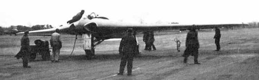
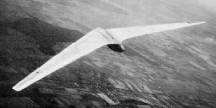
V.1 was the prototype, designed as a single seater with twin B.M.W. 109-003-1 jets, which were not ready when the airframe was finished. It was accordingly completed as a glider with fixed tricycle landing gear and extensively test flown at Oranienburg during the summer of 1944. D.V.L. instrumented it for special directional damping tests to determine its suitability as a gun platform. First flown on 1 March 1944, flight results were very favorable, but there was an accident when the pilot attempted to land without first retracting an instrument-carrying pole extending from the aircraft.
The design was taken from the Horten brothers and given to Gothaer Waggonfabrik. The Gotha team made some changes: they added a simple ejection seat, dramatically changed the undercarriage to enable a higher gross weight, changed the jet engine inlets, and added ducting to air-cool the jet engine’s outer casing to prevent damage to the wooden wing.
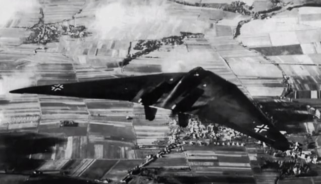
Göring believed in the design and ordered a production series of 40 aircraft from Gothaer Waggonfabrik with the RLM designation Ho 229, even though it had not yet taken to the air under jet power. The first flight of the H.IX V2 was made in Oranienburg on 2 February 1945. All subsequent test flights and development were done by Gothaer Waggonfabrik. By this time, the Horten brothers were working on a turbojet-powered design for the Amerika Bomber contract competition and did not attend the first test flight. The test pilot was Leutnant Erwin Ziller. Two further test flights were made between 2 and 18 February 1945. Another test pilot used in the evaluation was Heinz Scheidhauer (de).
The H.IX V2 reportedly displayed very good handling qualities, with only moderate lateral instability (a typical deficiency of tailless aircraft). While the second flight was equally successful, the undercarriage was damaged by a heavy landing caused by Ziller deploying the brake parachute too early during his landing approach. There are reports that during one of these test flights, the H.IX V2 undertook a simulated “dog-fight” with a Messerschmitt Me 262, the first operational jet fighter, and that the H.IX V2 outperformed the Me 262. Two weeks later, on 18 February 1945, disaster struck during the third test flight. Ziller took off without any problems to perform a series of flight tests. After about 45 minutes, at an altitude of around 800 m, one of the Jumo 004 turbojet engines developed a problem, caught fire and stopped. Ziller was seen to put the aircraft into a dive and pull up several times in an attempt to restart the engine and save the precious prototype. Ziller undertook a series of 4 complete turns at 20° angle of bank. Ziller did not use his radio or eject from the aircraft. He may already have been unconscious as a result of the fumes from the burning engine. The aircraft crashed just outside the boundary of the airfield. Ziller was thrown from the aircraft on impact and died from his injuries two weeks later. The prototype aircraft was completely destroyed after 2-hours flying.
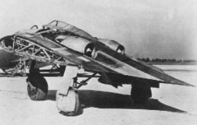
V.3 was being built by Gotha at Friedrichsrodal as a prototype of the series production version. The V3 was larger than previous prototypes, the shape being modified in various areas, and it was meant to be a template for the pre-production series Ho 229 A-0 day fighters, of which 20 machines had been ordered. The V3 was meant to be powered by two Jumo 004C engines, with 10% greater thrust each than the earlier Jumo 004B production engine used for the Me 262A and Ar 234B, and could carry two MK 108 30 mm cannons in the wing roots.
Work had also started on the two-seat Ho 229 V4 and Ho 229 V5 night-fighter prototypes, the Ho 229 V6 armament test prototype, and the Ho 229 V7 two-seat trainer. The Ho 229 V4 two-seat all-weather fighter, was in construction at Friedrichroda, but not much more than the center-section’s tubular framework completed as was the Ho 229 V5 two-seat all-weather fighter. The Ho 229 V6 projected definitive single-seat fighter version with different cannon, mock-up was in production at Ilmenau.
The Ho 229 A-0 projected expedited production version based on Ho 229 V6 was not built. The H.IXb (also designated V6 and V7 by the Hortens) projected two-seat trainer or night-fighter; not built.
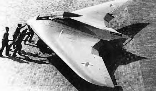
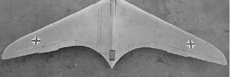
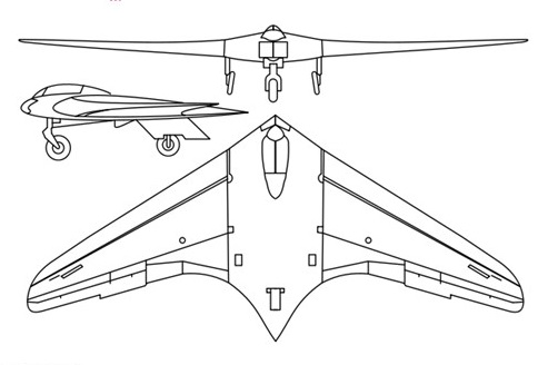
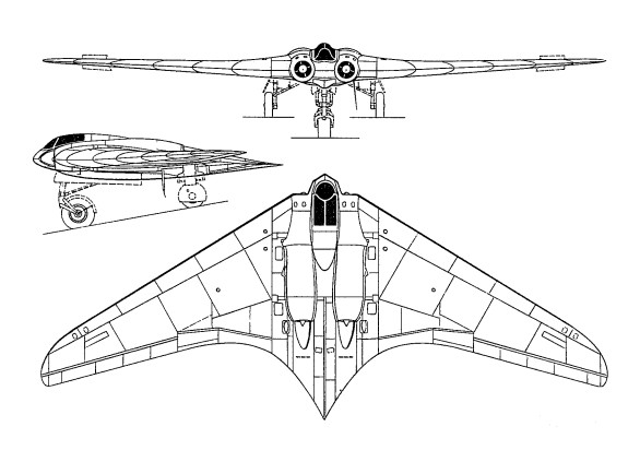
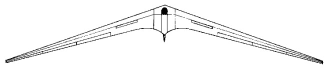
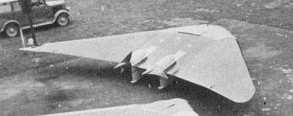
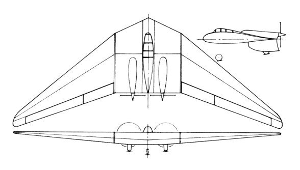
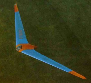
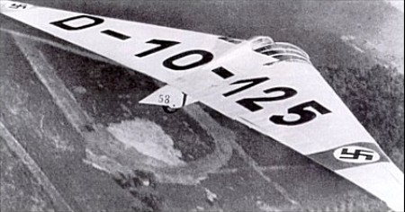
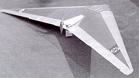
In shape, the H IX was a pure wing with increased chord at the center to give sufficient thickness to house the pilot and the jet units, which were placed close together on either side. The H IX started as a private venture and the Hortens were very anxious to avoid failure so they avoided aerodynamic experiments wherever possible. A lower sweepback was used than on the H V and H VII and laminar flow wing sections were avoided as a potential source of trouble. Wing section at the junction with the center sections was 14% thick with maximum thickness at 30% and 1.8% zero Cmo camber line. At the centerline thickness was increased locally to 16% to house the crew. The tip section was symmetrical and 8% thick. Horten also believed that since the compressibility cosine correction to drag was based on the sweepback of the maximum thickness line, the ordinary section would show little disadvantage. Wing twist was fixed by consideration of the critical Mach number of the underside of the tip section at top speed. This gave a maximum washout of 1.8°. Having fixed this, the CG was located to give trim at CL = 0.3 with elevons neutral. In deciding twist for high speed aircraft, CD values were considered in relation to local CL at operational top speed and altitude (10 km in the case of the H IX). Twist was arranged to give minimum overall drag consistent with trim requirements. The wing planform was designed to give a stall commencing at 0.3 to 0.4 of the semi-span. Wing structure comprised a main spar and one auxiliary spar or wooden construction with ply covering. The center section was built up from welded steel tube. Wing tips were all metal. The undercarriage was completely retractable and of tricycle type the front wheel folding backwards and the main wheels inwards. The nose wheel was castering and centered with a roller cam. When resting on the ground, wing incidence was 7° and the nose wheel took about 40% of the total weight.
The jet engines were installed at -2° to the root chord and exhausted on the upper surface of the wing at 70% back from the nose. To protect the wings the surface was covered with metal plates aft of the jet pipe and cold air bled from the lower surface of the wing by a forward facing duct and introduced between the jet and the wing surface. The installation angle was such that in high speed flight the jest were parallel to the direction of flight. Lateral and longitudinal control was by single stage elevon control flap with 25% Frise nose and compensating geared tap balance. (This system was also used on the H VII, see para. 4.6.) The pilots control column was fitted with a variable hinge point gadget, and by shifting the whole stick up about 2” the mechanical advantage could be doubled on the elevons for high-speed flight. Directional control was by drag rudders. These were in two sections, slight movements of the rudder bar opening the small (outboard) section and giving sufficient control for high speed. At low speeds when courser control was necessary the large movement also opened the second spoiler, which started moving when the small one was fully open. By pressing both feet at once, both sets of spoilers could be operated simultaneously; this was stated to be a good method of steadying the aircraft on a target when aiming guns. The Hortens stated that the spoilers caused no buffeting and claimed an operating force of 1 kg for full rudder, with very little variation in speed. A change was made from the original H VII parallel link system to improve the control force characteristics. With the new system, aerodynamic forces could be closely balanced by correct venting of the spoiler web, leading the main control load to be supplied by a spring. The cover plate of the spoilers was spring loaded to form an effective seal with the rudders closed; this device was used on most Horten spoiler and dive brake designs. On further models of the H IX it was proposed to fit the “trafficator” type rudder tried experimentally on the H VII.
Landing flaps consisted of plain trailing edge flaps (in four sections) on the wings, with a 3% chord lower surface spoiler running right across the center section, which functioned as a glide path control. The outer pair of plain flaps lowered 27° and the inner pair 30° – 35° on the glider version V.1. On V.2 mechanical trouble prevented the inner pair operating and all flying was done with the outer pair only. The center section spoiler could be used as a high speed brake and gave 1/3 g at 950 kph. No dive recovery flap was considered necessary. Proper performance tests were not done on V.2 before its crash and top speed figures were calculated values, checked by Messerschmitts. The following figures were remembered by Reimar Horten: All Up Weight, Including Ammunition and Armour: 8,500 kg (18,700 lbs.) All Up Weight, Excluding Ammunition and Armour: 7,500 kg Wing Area: 52 sq.m (566 sq.ft.) Wing Loading: 33 lb./sq.ft. Fuel (I2 Crude Oil): 2,000 kg (4,400 lbs.) Performance at 7,500 kg (16,500 lbs.) Takeoff Run: 500 m Takeoff Speed (10 deg Flap): 150 kph (95 mph) (Note: This corresponds to a CL of 1.30 which is the stated stalling CL of the aircraft.) Top Speed (at Sea Level): 950 kph (590 mph) (CDo estimated to be 0.011) Calculated ceiling was 16 km (52,000 ft). Engines would not work above 12 km as the burners went out. Rate of Climb at Sea Level: 22 m/sec (4,300 ft/min) In tests against the Me 262 speeds of 650-700 kph (400-430 mph) were obtained on about 2/3 throttle opening. This appears to be the only flight test figure available. Messerschmitt sent performance calculators to the Horten works to check their estimates. The method suggested by D.V.L. for getting the sweepback correction to compressibility drag was to take an area of 0.3 x the root chord squared at the center section as having no correction applied, and then apply full cosine correction over the outer wing. Sweepback angle was defined as that of the quarter chord locus. Test data was available for CDv. for zero sweepback. The Messerschmitt method was to base sweepback on the max t/c locus and to scale Mach number by the square root cos Ø. The H IX V.1 was flown by Walter Horten, Scheidhauer and Ziller. Scheidhauer did most of the flying (30 hours) at Oranienberg, Horten and Ziller flew for about 10 hours. D.V.L. instrumented the aircraft for drag and directional stability measurements. No drag results were obtained because of trouble with the instrument installation – apparently an incidence measuring pole was fitted which could be lowered in flight and glide path angle was obtained from the difference between attitude and incidence measurements. One day they landed without retracting the pole. Directional oscillation tests were completed successfully and an advance report was issued (10 pages of typescript) by Pinsker and Lugner fo D.V.L. The essence of the results was that the lateral oscillation was of abnormally long period – about 8 sec. At 250 kph and damped out in about 5 cycles. At low speeds the oscillation was of “dutch roll” type but at high speed very little banking occurred. Many fierce arguments took place at D.V.L. on desirable directional stability characteristics, the Hortens naturally joining the “long period” school of thought. They claimed that the long period would enable the pilot to damp out any directional swing with rudder and keep perfectly steady for shooting. It was found that by using both drag rudders simultaneously when aiming, the aircraft could be kept very steady with high damping of any residual oscillation. Lateral control was apparently quite good with very little adverse yaw.
Longitudinal control and stability was more like a conventional aircraft than any of the preceding Horten types and there was complete absence of the longitudinal “wiggle” usually produced by flying through gusts. Tuft tests were done to check the stall but the photographs were not good enough for much to be learned. Handling was said to be good at the stall, the aircraft sinking on an even keel. There seems to be some doubt, however, as to whether a full stall had ever taken place since full tests with varying CG and yaw had not been done. Although the stick was pulled hard back, the CG may have been too far forward to give a genuine stall. Directional stability was said by Scheidhauer to be very good, as good as a normal aircraft. He did not discuss this statement in detail as he was obviously very hazy about what he meant by good stability and could give very little precise information about the type and period of the motion compared with normal aircraft. Scheidhauer had flown the Me 163 as a glider and was obviously very impressed with it; he was confident enough to do rolls and loops on his first flight. We asked him how the H IX V.1 compared with the 163; he was reluctant to give an answer and said the two were not comparable because of the difference in size. He finally admitted that he preferred the 163 which was more maneuverable, and a delight to fly (he called it “spielzeug”).
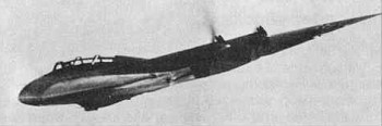
The H IX V.2 with two Junkers 109-004B-1 jet engines was flown at Oranienburg only by Ziller and completed about 2 hours flying before its crash. The redesigned Ho IX V2 demonstrated speeds of up to 960km/h before it was destroyed. This occurred after an engine failure – the pilot undershot, tried to stretch the glide and stalled. One wing must have dropped, for the aircraft went in sideways and Ziller was killed. Before the crash a demonstration had been given against an Me 262; Horten said the H IX proved faster and more maneuverable, with a steeper and faster climb.
In spite of the crash, Horten thought the single engine performance satisfactory and said the close spacing of the jets made single engined flying relatively simple. Such promise encouraged the RLM to instruct Gothaer Waggonfabrik to assume development of the design, and a third prototype, the Go 229 V3, was produced with 1000kg thrust Jumo 109-004C turbojets, but was prevented from flying by the end of hostilities in May 1945.
V3
Work had also started on the two-seat Go 229 V4 and Go 229 V5 night-fighter prototypes, the Go 229 V6 armament test prototype, and the Go 229 V7 two-seat trainer, No progress had been made on 20 pre-production Go 229A-0 fighter-bombers, on order at the end of the war, that were intended to carry two 1000kg bombs and four 30mm MK 103 cannon.
Production was assigned to the Gothaer Waggon Fabrik, which main facilities were placed in the city of Gotha. An initial contract for 20 pre-production aircraft was awarded to the firm and works begun. The Gotha engineers introduced several and extensive modifications to adapt the design to the series production. The construction was subcontracted to the Ortlepp Möbel Fabrik at Friedrichroda. This was a logical solution as the GWF facilities had all their capabilities compromised in the production of parts for other aircraft manufacturers. Besides its management was pushing the RLM to adopt their flying wing designs and this way cancel the Horten IX series production. The Gotha designs were known as the Gotha P-60 with three different versions A, B and C. When the Ortlepp Works at Friedrichsroda were overrun by troops of the American 3rd Army’s VII Corps on April 14, 1945 they found inside of the building three FW in different construction stages: The V3 was nearly complete. The jet engines were installed and most part of the works on the skin had finished.
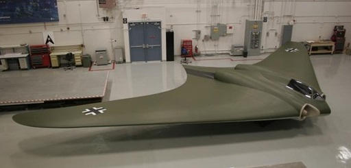
After the end of the war, the V4 and V5 disappeared. In some reports they are briefly mentioned but it’s quite likely that they were scrapped. The V1, the non-powered prototype, was also destroyed and last seen at Kassel Rothwesten airfield. We do not know where in Europe the V3 was taken, where it was crated and loaded in a ship. According to the NASM the HMS Reaper packing list is not known, but there were other vessels with war booty that left Europe. What is sure is that the V3 was shipped to the USA and arrived by train to Freeman. Today, the Horten IX V3 is in store at the Garber Building 22 awaiting a restoration.
Ho-IX V2 Engine: 2 x 2 x Jumo-004, 900kg Take-off weight: 6900 kg / 15212 lb Empty weight: 4844 kg / 10679 lb Wingspan: 16.76 m / 55 ft 1 in Length: 7.46 m / 24 ft 5.75 in Height: 2.6 m / 8 ft 6 in Wing area: 52.8 sq.m / 568.33 sq ft Max. speed: 960 km/h / 597 mph Crew: 1
Horten Ho 229A / V3 manufacturer’s estimates Powerplant: 2 × Junkers Jumo 004B turbojet, 8.7 kN (1,956 lbf) each Wingspan: 16.76 m (55 ft 0 in) Wing area: 50.20 m² (540.35 ft²) Length: 7.47 m (24 ft 6 in) Height: 2.81 m (9 ft 2 in) Empty weight: 4,600 kg (10,141 lb) Loaded weight: 6,912 kg (15,238 lb) Max. takeoff weight: 8,100 kg (17,857 lb) Maximum speed: 977 km/h (estimated) (607 mph) at 12,000 metres (39,000 ft) Service ceiling: 16,000 m (estimated) (52,000 ft) Rate of climb: 22 m/s (estimated) (4,330 ft/min) Wing loading: 137.7 kg/m² (28.2 lb/ft²) Thrust/weight: 0.26 Armament: 2 × 30 mm MK 108 cannon Bombload: 2 × 500 kilograms (1,100 lb) bombs / R4M rockets Crew: 1
Go 229A 0 Engines: two 1000 kg (2,205 lb) thrust Junkers Jumo 109 004C turbojets. Maximum speed 1000kph (621mph) at 6100 m (20,015 ft) Landing speed 130 kph (81 mph) Maximum take off weight: 8500 kg (18.739 lb) Wingspan 16.78 m (55 ft 5/8 in) Length 7.47 m (24 ft 6 1/8 in) Wing area: 51.5sq.m (554.36 sq.ft). Armament: four 30 mm MK 103 cannon and up to 2000 kg (4,409 lb) of bombs.
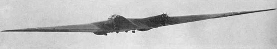
This was to have been a flying model of a proposed six-engined trans-Atlantic passenger transport weighing 100,000 kg. The span was to be 40 m with an aspect ratio of 10 and sweepback of 28 degrees. Power units were six Argus AS 10 C engines. To make the aircraft attractive to R.L.M. and thus get backing for the project, the Hortens added a rear loading cargo carrying body with an internal space approximately 14’ x 10’ x 6’; this was not part of the design for the full size aircraft. With construction under way, another modification was made (but not disclosed to R.L.M.). This consisted of removing the nose of the cargo body, replacing the nose wheel by wheels on either side of the body and putting a large venturi tube with a 2m x 2.7m throat inside to form a flying wind tunnel. They expected to get about 500 mph airspeed in the throat combined with low turbulence – this they proposed to check by the sphere drag method. Later they hoped to be able to test models of their aircraft which could be made of wood because of the absence of dust in the airstream. Construction was proceeding at Gottingen and was 50% complete at the cessation of hostilities. The steel tube framework for the venturi center section was finished. Estimated Weight and Performance Figures Max. all up weight as a wind tunnel: 9,000 kg Max. all up weight as a cargo carrier
Without takeoff assistance: 15,000 kg
With rocket assisted takeoff: 20,000 kg At 23,000 kg the sea level rate of climb at full power would be zero. At 9,000 kg rate of climb at 180 kph was expected to be 6.5 – 7 m/sec. Estimated trimmed CLmax’s were:
No Flaps: 1.4
With Flaps: 1.6
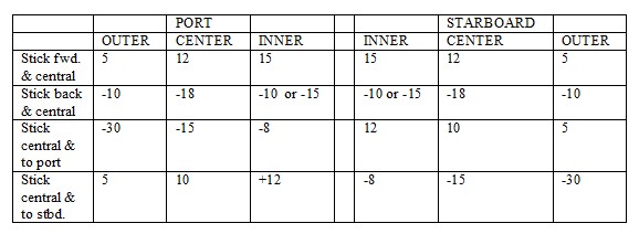
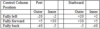
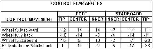
CL for Takeoff: 1.1 The design of the wing and controls was similar to that of the Horten IV. Washout was 7 degrees, to give trim without elevator deflection at cruising CL. Elevons were the three stage type with 35% Frise nose on the outer flap, and 22% on the middle and inner flaps. Compensating geared tabs which could also be used a longitudinal trimmers were fitted to the inner flaps. Maximum control deflections were a follows: (Note: All figures in degrees)
Trailing edge split flaps with a constant chord of 80 cm were to be fitted between the engines. Drag rudders were of the H VII “trafficator” type with vent hole balance plus spring centering. Projection was about 1 meter. Wing Root thickness is about 16%, with the usual reflexed center-line, graded to an 8% symmetrical tip section. Wing structure was in seven parts; a welded steel center section with pilot and co-pilots seat and three outer wooden wing panels per side. The wooden structure was of single spar D-tube form with subsidiary trailing edge ribs. At the factory in Gottingen the center section was found in a semi-complete state, D-noses for the inboard wing panels were finished and spars and ply noses for the outer panels were under construction. Much of the work on components such as engine bearers, petrol systems, undercarriage etc., had been completed and the six engines were in crates at the works, with one spare. Unfortunately all drawings had been taken and many of them seem to have been buried by Horten employees near Kilenburg, in the Russian sector. The fixed main wheels were arranged in tandem pairs on either side of the fuselage and took 85% of the static weight of the aircraft. The castering nose wheel was retractable on the cargo version and had to be mounted on a stalky strut because of the high wing layout. Static ground incidence was 2.5 degrees.
Ho-VIII Max take-off weight: 8000 kg / 17637 lb Empty weight: 5000 kg / 11023 lb Wingspan: 40 m / 131 ft 3 in Length: 16.5 m / 54 ft 2 in Height: 3.85 m / 12 ft 8 in Wing area: 146 sq.m / 1571.53 sq ft Max. speed: 280 km/h / 174 mph Range w/max.fuel: 6000 km / 3728 miles Crew: 3
The H VII was projected in 1938 and the first of the type was built by Peschke at Minden in 1943. It bears a general resemblance to the modified H V in layout and control design and used the same outer wing panels: the span was the same (16m) the sweepback slightly greater (34 degrees) and aspect ratio 5.8 instead of 6.1. Its function seems to have been that of a high speed two-seater communications aeroplane and trainer for tailless pilots. Engines were Argus AS 10 C of 179kW / 240 hp. Altogether two were completed and flown and a third was nearing completion at Minden when the district was occupied by the Allies. Two aircraft were damaged beyond repair and the third fell into Russian hands at Eilenburg. Single stage elevon control was used on the H VII with 25% Frise nose and geared tab. Inboard of the elevons was a plain flap and in the middle trailing edge split flaps extending for the full width of the center section. Initially the graded flap angle principle was used, the part between the engines opening to 60 degrees, between the engine and the outer wing panels to 45 degrees, and the plain flap on the wing lowering to 20 degrees. When R.L.M. ordered the design in quantity however they asked for it to be simplified and for landing speed to be raised to give pilots more realistic training for high speed aircraft. The plain flap was accordingly locked up on the second aircraft and omitted altogether on the series production model. Plug spoiler drag rudders of the H IV type were used on the first aircraft. These tended to suck open and had to be held closed by springs. They were not very satisfactory from the point of view of control forces and feel, and after about 10 flights they were scrapped and replaced by a new “trafficator” design. This was simply a bar which projected 40 cm in a spanwise direction from the wing tip when rudder was applied and retracted flush with the wing surface when not in use. Vent holes were cut to adjust aerodynamic balance. The vent holes allowed flow through the bar and deflected the flow sideways to generate a self-closing aerodynamic force. This was supplemented by a spring loading and the two components adjusted to give satisfactory feel on the rudder bar. This type of rudder was claimed to be cheap and easy to make and generally more satisfactory then previous designs.
The center section being of welded tube construction and the wings of single spar wooden construction with ply covering. The undercarriage was a completely retractable four-wheel layout, the front wheel pair taking about 50% of the total weight when resting on level ground. The constant speed airscrews were driven through extension shafts with a thrust ball bearing and rubber flexible coupling at the engine end and a self aligning ball bearing at the airscrew end mounted on a cantilever form the main structure. Outer wing panels were of the same aerodynamic shape as those of the H V. At the center line the section was 16% thick with 1.8% camber (zero Cmo) graded to 8% symmetrical tip sections. Wing twist was 5 degrees; 2 degrees linearly and 3 degrees parabolically distributed. The aircraft trimmed with elevons neutral at 260 kph (CL = 0.16).
The following performance data were quoted by Reimar Horten from memory: Flying weight (minimum) 2,900 kg Flying weight with full equipment 3,200 kg Engines 2 x 240 hp Argus AS 10 C (normally aspirated) Sea level (crusing speed (180-200 hp per engine) 310 kph Sea level (top speed) 340 kph Normal take-off speed 110 kph Ground run 250 meters Sea level rate of climb at 180 kph (full power) 7 m/sec. Ceiling 6,500 meters CLmax = 1.2 no flaps CLmax = 1.6 with all flaps Delta CL due to plain flap was 0.1
Reimar Horten said that prior to the first flights at Scheidhauer on the H VII, his brother Walter had supervised the CG’ing of the aircraft and mistakenly put ballast in the nose because the measurements were made with a steel tape with 10 cm missing from the end. Scheidhauer’s commented that the aircraft had to be brought in at a minimum speed of 120 kph, with the stick nearly right back, if the nose was to be lifted for the hold off; the aircraft then floated (stick fully back) until 90 kph before touching down. Normal take-off procedure was to accelerate to 120 kph and then pull the stick back when the aircraft immediately took off and climbed away. Apparently it could be unstuck at 90 kph by pulling back hard but would not climb until 120 kph had been reached. It was impossible to stall the aircraft with the CG in this position; the general behavior was said to be “good natured”. Walter flew the H VII (with the CG in its correct position) on 30-40 occasions, a total flying time of about 18 hours. (Scheidhauer’s time was also about 18 hours). Apparently the change in CG brought the approach speed down to about 100 kph and the aircraft could be touched down on the rear wheels. It was not certain that a complete stall could be produced in steady flight. With the stick fully back the aircraft sank on an even keel with fair lateral control. Lateral control was pleasant, the 25% Frise balance eliminated adverse yaw and virtually enabled flying on two controls. Tests with the “trafficator” drag rudder showed that single engine flight could be maintained with half rudder and a little sideslip; turns could be made in level flight against the dead engine. On one test the pilot was carrying out a single engine approach when he realized that he had stopped the engine supplying the undercarriage hydraulics and could not lower the wheels. He was able to climb away, start the dead engine and made a normal landing.
Ho-VII Engine: 2 x Argus As-10, 180kW Max take-off weight: 2000 kg / 4409 lb Empty weight: 1550 kg / 3417 lb Wingspan: 16 m / 52 ft 6 in Length: 7.5 m / 24 ft 7 in Height: 2.5 m / 8 ft 2 in Wing area: 44 sq.m / 473.61 sq ft Max. Speed: 350 km/h / 217 mph Crew: 2
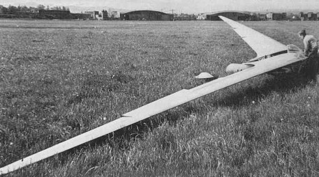
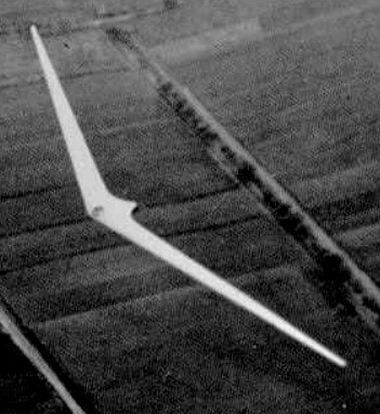
In general layout of the Ho.VI was very similar to the H IV. The span was increased to 24 m (78.7’) accompanied by a decrease of 5% in wing area, giving an aspect ratio of 32.4. The object in building the H VI was to achieve the most efficient high performance sailplane regardless of cost. Two were built and the first was tested late in 1944. It was performance tested by the relative sinking speed method previously described, using a calibrated H IV for the second glider. The Hortens were very pleased because it was better than the D 30 (same span and wing loading) over the whole speed range. Aerodynamically there were no new features of special interest compared with the H IV. Wing sections and control systems remained the same. The structural design had to be refined in order to get sufficient bending strength in the very thin cantilever. The main spar was made up of laminations of plain wood and “bignefel” (a compressed impregnated wood) to give extra strength at the root, and a special wing root fitting using four taper pins in place of the normal two was devised to distribute the concentrated loads at the root. The torsion box design was modified also to increase the wing torsional stiffness, since at high speed it had been found that an unstable short period longitudinal oscillation, involving wing twist, could develop. The speed at which the damping of this oscillation became zero on the H VI was found to be about 180 kph.
The H VI is of interest only as a high performance sailplane for record breaking purposes. It is too costly and difficult to handle for general use. The second aircraft of this type built was found intact near Horsfeld; the first aircraft was found destroyed near Gottingen, where it had been flying.
Ho-VI Wingspan: 24.2 m / 79 ft 5 in Wing area: 17.8sq.m Empty weight: 330 kg / 728 lb Gross Weight: 410kg Payload: 80kg Wing Load: 23kg/sq.m Aspect ratio: 32.4 to 1 MinSink: 0.45 m/s 70 kph L/DMax: 45 83.5 kph Seats: 1
The H V was designed form the outset as a powered aircraft using two Hirth H.M. 60 R motors driving oppositely rotating propellers through extension shafts. It has a span of 52.5 feet, aspect ratio of 6:1, and a quarter chord sweepback of 32 degrees. Engines were completely buried and drove propellers on extension shafts raised relative to the engine crankshaft and driven through a reduction gear. The undercarriage was of fixed tricycle type with castoring nose wheel and trousered main wheels. The nose wheel actually too 55% of the static weight when on level ground. Three examples were built. The first, built at Ostheim in 1936 was constructed of plastic material with riveted sheet plastic covering. Pilot and passenger were contained entirely in the wing contour and the nose wheel was retractable. This aircraft crashed on its first flight, due mainly to its unorthodox waggle-tip control. The second version used more normal control methods and conventional construction, it was started in 1937 and flew successfully. In 1941 it was completely rebuilt as a single-seater, but retained the same control system. In its original form the H V was fitted with waggle tip control in which the fore and aft sweep of the wing tips was geared to the stick, producing incidence change by a skew hinge arrangement. The aircraft crashed on it first flight due to the control taking charge after a bounce during landing. The reason for the accident was obscured by a failure of one engine but the control system was not regarded as satisfactory by the Hortens who later developed the idea further on an H III. They considered that damping is necessary to prevent the tips oscillating under suddenly applied acceleration (as occur during take off and landing). The second aircraft in both its forms had a two stage elevon control rather similar to the H III. Maximum control deflections were as follows:
The outer control flaps had a 20% Frise nose and assymmetrically geared tabe to compensate the non linear moment characteristics of the nose balance. The inner flap pair had round noses. Split trailing edge flaps were fitted to the center section, the flap between the engines lowering to 60 degrees and the part outboard to 45 degrees. The inner elevon flaps dropped to 30° when the center section flaps were lowered and still operated as elevons about this new zero position. The idea of using graded flap deflections originated from a hunch of the Hortens that the sudden discontinuity and greater spanwise flow with ungraded flaps might cause stability and control troubles. They later found that this fear was unfounded and gave up the graded deflection principle. Rudder control on the second two aircraft was by split nose flaps on the H III pattern. A great deal of flying was done on the second and third H V’s, including about twenty flights on the latter in 1943 by Prof. Stuper of A.V.A. Gottingen. The Hortens themselves had lost interest in the H V because later designs incorporated many improvements. Stuper has also flown the H IIId with Walter Mikron engine. Tests at A.V.A. were undertaken at the request of D.V.L. who wanted information on single engine characteristics and an unbiased comparison between tailless and conventional handling qualities. Stuper’s comments were as follows: Longitudinal dynamic stability was good and no fundamental different from a conventional aircraft could be noticed. In rough air he thought it had a more abrupt pitch response than normal, which was only a disadvantage if gun platform steadiness was needed. (Walter Horten thought this effect might be due to the low wing loading (6 lb/sq.ft.) on the H V and Stuper agreed that this might be so). Lateral stability appeared satisfactory. No tendency to “dutch roll” instability was found and no arratic changes of heading due to low Nv and Yv were noticeable. Stuper was in fact expecting trouble from this source but failed completely to find any. He added that his impressions were purely qualitative as they had no time to instrument the aircraft. Controls were light and effective, with the exception of the rudder, which was heavy and not effective enough. Aileron was heavier than the elevator “in the ratio 4:3”. With the stick back, aileron movement was restricted, which Stuper thought a bad point since plenty of aileron was useful in an approach in gusty weather. The aircraft was in trim virtually over the whole speed range without movement of the elevator trimmer. When flaps were lowered there was a slight nose heavy tendency which could easily be held. Summing up, Stuper said that aileron and elevator control were quite normal but rudder control needed improvement. Behavior at the stall (flaps down) was very satisfactory, the nose dropped gently and the aircraft gained speed. Wing dropping could be induced if the aircraft was stalled in a yawed attitude but normally the wings remained level and ailerons still effective, thought restricted in movement. The stall was reached with the stick not quite fully back; only one CG position was tested. Stalling speed was about 70 kph. Flight on one engine was possible, without rudder, at 120 kph by flying with 10 degrees of bank and 80% aileron. Rudders were not used much because they were so heavy, although Walter Horten claimed that at 130 kph single engine flight could be maintained on rudder only (engine nearly at full power) if the pilot was strong enough. Ground maneuvering was easy using throttles and wheel brakes. During take-off the aircraft could quite easily be kept straight until the drag rudders became effective, and flew itself off the ground without assistance from the pilot – in fact it made very little difference what the pilot did with the controls during take-off. There was no tendency to bounce during the ground run. R.L.M. require that for normal tricycles, it should be possible to left the nose wheel before take-off speed is reached; Walter Horten thought this was unnecessary if the aircraft would fly itself off. Landing was quite straightforward and normally the aircraft settled down on all wheels at once. Stuper thought it was not possible to land on the main wheels first because the ground incidence was too high. Stuper had done some tests of take-off performance with flaps down, which resulted in his flying into a hanger and terminating the A.V.A.test programme. Apparently he landed and immediately (Walter Horten said not immediately) opened up to take-off again – after 530 meters he was 8 meters high and at that point entered the hanger. The airborne distance was about 150 meters. Although the split flaps in front of the propellers caused poor thrust, there were apparently no vibration problems. Summarizing his impressions on the H V, Stuper said that it was hardly fair to compare it with conventional aircraft with many years more development behind them but it was nevertheless, a good example of tailless design and a perfectly practical aeroplane – if anyone wanted tailless aeroplanes. His main suggestion for improvement was in the rudder control.
Ho-V Wingspan: 16 m / 52 ft 6 in Max. speed: 260 km/h / 162 mph
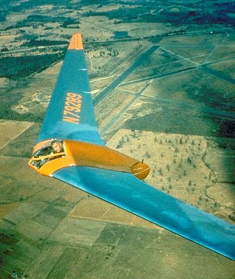
The span was the same as that of the H III but aspect ratio was increased from 10.7 to 21.1, and the control system further developed. In order to retain their finless wing layout and get the maximum aerodynamic efficiency, the pilot was put in a prone position with his body in a 27% thickness ratio egg and his knees and legs in a small leg well. The well also supported the rear skid (or wheel in the case of the H IVb). An example of the HIV was found at Göttingen in good condition and was brought back to R.A.E. for test flying. It has completed 500 hours flying since its construction in 1942, including a cloud flight of 1-hour on instruments; such a flight demonstrates that stability and control and the comfort of the prone position must be satisfactory.
The three stage control flaps were all geared to the spectable type control wheel and operated on the same general principle as the earlier two flap control on the H III. The following table gives the (measured) flap movements corresponding to full control by the pilot.
It will be seen that the outer flap works principally as up going aileron whereas the “climbing elevator” action comes mainly from the middle flap and “diving elevator” action from the inner flap. Down going aileron, needed to neutralize pitching moments, comes from the inner and middle flaps together. The center and inner flaps were unbalanced, with round noses, the tip flaps Friese balanced with a skew hinge giving 39% balance at the inboard end and zero balance at the tip. This scheme gave the required aileron yawing moments without making the control flap at the tip vulnerable when a wing tip scraped the ground. Drag rudders were of the upper and lower surface spoiler type placed immediately ahead of the outer control flap; the upper surface spoiler had a vented web. To open the rudders the pilot had to press with his toes, moving the foot from the ankle against a spring loading on the pedals which gave “feel” to the control. By pressing both feet together he could open both rudders simultaneously, thus giving extra drag for glide control. Rudder operation was said to cause no buffeting of the control flaps. The movement transmission from the pilot’s pedal included a cam plate cut to give no rudder movement for negative movement of the pilot’s foot (i.e., pressure on the opposite pedal) and an approximately linear relationship between pedal movement and rudder projection for positive movement (i.e., pressure on the pedal). All controls were operated by push rods, the inner and central flaps and the drag rudders being moved by skew-hinge cantilevers. In the IVb the skew hinge principle was extended to the outer flap operation also. The method of operating the control flaps was simple to construct and eliminated all external control horns. Longitudinal trim was obtained by an internal bungee “spring” which can be adjusted to take any out-of-balance aerodynamic loads on the elevator control. There were no landing flaps by large spoiler type dive brakes were provided, which could be used to give variable drag for glide path control. The H IV used reflexed cambered sections (zero Cmo) of R.A.F. 34 type, changing to assymetrical section at the wing tip. The large wing dihedral of 5 percent was used to give adequate wing tip clearance. Reimar Horten considered that aerodynamically this might be on the large side but advisable for practical reasons. It should be remembered that both the H III and H IV have an abnormally low value for the lateral relative density Uso that unusual values of Lr and Nv would be permissible without dynamic instability resulting. Performance was measured by flying the H IV against the D 30, a conventional high performance glider which had been carefully performance tested by D.V.L. to form a “standard”. The essence of the method was to two both aircraft up together and let them glide down from about 10,000’ at a series of speeds, measuring the relative height photographically, at intervals. From these tests the best gliding angle of the H IV was found to be 1 to 37 and the minimum sinking speed 1.7 ft/sec. Minimum sinking speed was slightly less than the D 30, but at high speeds the d 30 was better. Scheidhauer, Horten’s chief test pilot, has done the majority of the flying in Horten IV’s (about 1000 hrs) and his comments are worth recording. He was a strong advocate of the prone position – in his own words “it has nothing but advantages.” All H IV controls he described as very light, he flew the glider with “two fingers”. The elevator was apparently rather sensitive compared with the aileron but not unpleasantly so. Aileron application produced no adverse yaw – a definite improvement after the II and III – and could reverse a 45 degree banked turn in 5 secs. at 70-90 mph, which is better than the average sailplane. Longitudinal stability he thought satisfactory but he commented on a “wiggle” which was produced by flying through gusts; this is apparently a sharper pitch response than for a conventional sailplane, but well damped, quite harmless and requiring no corrective action by the pilot. A true stall could not be produced with normal elevon adjustment because of increasing static stick fixed stability at the stall, which used up available elevator power before the wing tips were stalled. Spins could only be produced by applying full aileron and rudder with the stick hard back; recovery was easy. Stability and controllability on tow were excellent. Scheidhauer described a competition in which a number of sailplanes were aero-towed form Grunau through the very turbulent air in the “standing wave” from a nearby mountain; the rough air had to be negotiated on tow to get to the area of rising currents. All the instructors from the school at Grunau were flying conventional sailplanes and broke their two lines without exception. Scheidhauer in his H IV managed to get through and soar in the standing wave. He attributed his success partly to his own skill and partly to the good controls of the H IV plus his ability to use the tip rudders together to check surging in the tow rope. Take-off seems to present some problems to a pilot new to the aircraft. It seems that the short undercarriage base, responsive elevator and small wing tip clearance can produce a very erratic take-off if the pilot is not smooth and precise in his control movements. Construction followed the normal Horten practice, but the wing panels were made with detachable tips of sheet clektron. This was necessary because the narrow chord at the tip made accurate construction in wood very difficult. The center section was of welded steel tube, with perspex nose and a large jettisonable access cover behind the main spar. The front skid was retractable and fitted with a wheel which automatically dropped off as the skid retracted. The pilot’s harness was modified from the original version, being a single broad strap passing under the buttocks. This was released by the same handle that jettisoned the access cover. The pilot’s parachute was stowed in a pocket on the cover and connected to the pilots harness by short straps. In this was the pilot was relieved of the weight of the pack, which would otherwise have caused some discomfort on a long flight. Flying instruments included a low reading A.S.I. driven by a venturi, electrical turn and bank indicator, sensitive variometer, high reading variometer, altimeter and clock. Oxygen equipment comprised two bottles, pressure gauges, reducing valve and economizer, and provision was made for electrically heated clothing. Ventilation was under the pilot’s control. The pilot position could be adjusted for varying pilot size and a chin rest with adjustment for height was provided. The pilot was prevented from sliding forward by shoulder rests and the reaction of his thighs against the knee well. Comfort appeared to be satisfactory when we tried the bed but elbow and shoulder movement was restricted which constrained one to stay in the same position all the time.
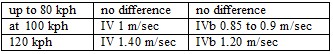
Superficially the IVb resembles the IV very closely but the aerodynamic changes were a fundamental experiment. The Hortens intended to produce a laminar flow sailplane with superlative high speed performance – in this they were partially successful but they sacrificed too much on the stability and control to make the venture a real success. Production had been started, prematurely, at the rate of about two a month. Wing sections were derived from the Mustang section which had been measured by D.V.L. for captured aircraft and tunnel tested. The Hortens were excited by the low tunnel drag figures and designed the H IVb to exploit them. The root section was the original Mustang profile, changing to an uncambered section with the same fairing shape but reduced thickness at the tip. Wing twist was reduced (compared with the IV) to 5.6 degrees to get the greatest spanwise extent of laminar flow, and sweepback reduced to 2 degrees to get the CG farther back relative to the mean chord (this was necessary because the aerodynamic center of the basic wing section was farther aft). It is interesting that although Cmo was not zero for the root section, the high aspec ratio enabled the glider to be designed to trim, elevons neutral, at the required top speed (140 mph) without needing excessive twist. The wing structure ahead of the main spar was a ply sandwich monocoque with Tronal filling. Tronal was an expanded wook with specific gravity 0.1 to 0.09, invented by a Dr. Barschfeld of Dynamit A.G., Troisdorf (near Cologne). The sandwich was made up on molds, with outer ply 1 mm thick and inner ply .8 mm; the filling was 20mm at the root tapering to 5 mm at the tip. The nose sections were stuck onto the front of the main spar with supporting ribs every 2 meters. Between the main and rear spars normal ply covering was used, insufficient Tronal being unavailable for sandwich construction all over. Waviness in a chordwise direction was not controlled or measured. Sag (spanwise) between ribs had been measured on the IV and eliminted on the IVb. Special care was taken to kep dust off the wings; wing dust covers were made and all handling was done with gloves on. Control circuit mechanism remained the same except for the outer flaps which were also operated by a skew hinge lever on the IVb. The dive brakes were moved back to the rear spar to suit the revised wing structure No transition measurements were made on the IVb, but it was flown against a calibrated IV and the following relative sinking speeds measured.
The change of section raised the stalling speed from 45 kph on the IV and to 60 kph on the IVb. The handling characteristics were very unsatisfactory. A wing tip stall occurred followed by wing dropping and spinning. The first aircraft crashed for this reason after the pilot got into trouble in a cloud. An attempt was made to improve matters on the second glider by clipping the span from 20.25 meters to 18.5 meters but results were disappointing. As a cure on the final design a reversion to the old H IV tip section was proposed, the theory being that section stalling characteristics were bad due to the sharp nose radius. Partial breakaway behind the maximum thickness point was suggested, aggravated by spanwise boundary layer drift which rendered the elevon ineffective. Horten thought the small wing tip Reynolds number made the use of low drag sections inadvisable.
Professor Dezso George-Falvy of Mississippi State University in a German Horten Ho IV glider – one of two to survive the Second World War. (1960)
In 1938, with this official backing, the Hortens set up a facility at Berlin’s Tempelhof Airport, where they constructed the Ho III sailplane. The first H III was built at Templehof Berlin in 1938 and the second (H IIIb) was built by Peschke Flugzeugban, also in Berlin. The main change from H II were increase span (20 m), reduce sweepback (23degrees) and modified lateral controls. The outer wing panels this time had three movable flaps. The innermost was again a landing flap, but the outer pair were geared so that the outer flap had a large range of upward deflection and, only slight downward movement and, the inner flap large downward movement and slight upward movement. This arrangement reduced unfavorable yawing moments due to aileron by making use of differential aileron movement, but avoided the change in longitudinal trim by the opposing differential of the inner flap pair. In high speed flight the nose down trim was provided mainly by the inner elevon section moving downwards, the outer flap deflecting only slightly; this had the advantage of relieving the tips of torsional loads at high speed. Aerodynamic balance was again by geared tab on sub types IIIa and b, but on IIId, f, and g the outer flap had a 20% Friese nose: out of balance aerodynamic loads on the elevators were trimmed by a rubber bungee trimmer.
Ho.IIId
Drag rudder design remained the same as for the H II.
The H III seems to have been a successful and useful type, for 14 were built altogether and several different sub-types developed. Production of some of the sub-types was still going on in 1945. The following variations on the original theme were produced:
IIIa – Original design
IIIb – Similar, but with outer elevon flap not extending to the wing tip.
IIIc –
Same as IIIa but with a fixed front plane. One of these was built, for the 1938 Rhon contest. Very little flying experience was obtained. The idea was to improve CLmax.
IIId – Standard wings fitted to a special center section with 32 hp Volkswagen engine and folding propeller. The idea was to produce a high performance sailplane with auxiliary engine for takeoff and climb, which could be shut off for soaring without impairing the performance as a sailplane. Center sections (Opel engine with gear drive) were being produced at Tubingen at the rate of two a month. 12 partly finished were in the workshop in June 1945. Finished parts were sent to the Wornberg and assembled with wings made at Darnsdorf. Performance with power was stated to be: Ground run: 70 meters Rate of climb: 2 m/sec. Cruising speed: 110 kph Max. speed: 130 kph The engine installation was take straight from the Volkswagen complete with exhaust system and electric starter; it weighed 240 lbs.
IIIe – H III glider with waggle tips. On this aircraft, remains of which were found at Gottingen, the tips were operated directly by the pilot.
IIIf –
Same as the IIIb, but with prone position for the pilot. A specimen of this type was found at Gut Nierstein with modified controls. The outer flap had a Frise nose, (as on H IV), spoiler type drag rudders were fitted in place of the usual leading edge split flaps, and H IV type dive brakes installed. The prone piloting position eliminated the need for the head fairing used on the other H III’s and gave the pilot a much better view.
IIIg – Special two-seater center section with tandem seats. Specimens were found at Zimmern and Hernberg. This type was used for training purposes.
H IIIh / Ho-229 – One built in 1944.
No independent opinions are available on the flying qualities of the H III series, but Reimar Horten was insistent that it was a very straightforward aircraft from the pilots point of view. He stated that any glider pilot with five hours experience could be safely sent off solo in an H III.
Horten H III a Wing span: 20.4m Wing area: 36sq.m Empty Weight: 220kg Payload: 80kg Gross Weight: 300kg Wing Load: 8.3kg/sq.m Aspect ratio: 11.6 L/DMax: 28 60 kph MinSink: 0.48 m/s 45 kph Seats: 1
Horten H III c Wing span: 20.4m Wing area: 36sq.m Empty Weight: 220kg Payload: 80kg Gross Weight: 300kg Wing Load: 8.3kg/sq.m Aspect ratio: 11.6 L/DMax: 28 60 kph MinSink: 0.48 m/s 45 kph Seats: 1
Horten H III f Wing span: 20.5m Wing area: 37.5sq.m Empty Weight: 280kg Payload: 80kg Gross Weight: 360kg Wing Load: 9.6kg/sq.m Aspect ratio: 11.1 L/DMax: 28 63 kph MinSink: 0.52 m/s 47 kph Seats: 1
H IIIh Wingspan 54 ft. Length 16.4 ft. Height 5.4 ft. Empty weight 586 lb Loaded weight 807 lb Wing area 344 sq. ft. Wing loading 2.25 lb/sq. ft. Glide ratio 24:1 Aspect ratio 8.48 Max speed 143 mph Best glide 45 mph
The Horton Ho.2 was of the same general layout as the H I but with sweepback increased from 19 degrees to 26 degrees and the lateral and longitudinal control combined in an elevon. Inboard flaps extending from elevon to center section were used to increase maximum lift and drag for landing. The first version was completed as a glider and the second fitted with a 60kW / 80 hp Hirth engine driving a pusher propeller in 1935. In this aircraft the pilot was seated in a reclining position and completely contained in the wing contour; a maximum level speed of 210 kph was achieved. This was tested in 1938 by Hanna Reitsch and attracted the attention of Ernst Udet, Director of the Technical Department of the German Air Ministry, who made funds available for further development.
Subsequently there more gliders were built, the last being completed in 1937 after which the type was abandoned in favor of the H III. The root wing section was change from the 20% symmetrical H I type, to a 20% section with reflexed camberline (zero Cmo) changing along the span to a symmetrical tip section. A balance tab was fitted to lighten the controls which were all pushrod operated. The structure was in three parts, as in all subsequent Horten designs. The center section being the welded tube and the outer panels of wood with a D-nose spar. The wheel undercarriage had brakes and the front wheel was retractable. Drag rudders consisted of lending edge flaps (as on the Horten III) opening against a spring.
From a translation of Hanna Reitsch’s report on one of the H II gliders, it is clear that lateral and directional control were still only partially satisfactory although characteristics at the stall were excellent. This feature is remarkable, for although a wing twist of 8 degrees was used the effect of the high taper and sweepback might be expected to overpower the beneficial effect of twist in delaying the tip stall.