Janowski J-3 Eagle

J-3 Eagle was the third, after Prząśniczka J-1 and J-2 Polonaise amateur single-seat aircraft, designed by Jaroslaw Janowski.

The aircraft of wooden construction featured Wortmann airfoil with flaperons all along the trailing edge, wingtip fuel tanks and composite landing gear legs. The aircraft was powered in succession by a modified Porsche car engine, a Rotax and a BMW R100 engines. The J-3 Eagle (Orzel) was produced using the pod-and-boom pusher arrangement, with a top-mounted engine and conventional landing gear similar to the J-1, and a T-tail stabilator and shoulder-mounted cantilever wings similar to the J-2. The wings used a 19% thick laminar airfoil and could be easily detached for ground transport.

A single example was built by Witold Kalita, J. Janowski and Marian Smith, for whom the aircraft was the intended. The J-3 Eagle was built from sketches, and no blueprints or plans of any sort were ever produced.

When Marian Nowak emigrated from Poland to Canada he took the J-3 with him. He flew the aircraft for 250 trouble-free hours, regularly making 375 mile commutes. However, he decided to take advantage of the detachable wings and transport it by trailer when he exhibited it at the EAA convention at Oshkosh in 1980 as the first amateur construction from the Eastern Bloc.

The Eagle initially flew with a 35 HP converted Porsche automobile engine, but Mr. Nowak also flew it with a Rotax 503, a Rotax 447, a 69 hp BMW motorcycle engine, and finally a water-cooled 3 cylinder Suzuki auto engine. Eventually Mr. Nowak sold the airplane, and the new owner tied it down outdoors where it unfortunately deteriorated beyond airworthy condition. The Transport Canada database listed it as last registered to Wieslaw Pawelkiewicz in April 2002, operating at Burlington, Ontario. It was donated to the Polish Aviation Museum in 2003 by the last owner, Wieslaw Pawełkiewicz of Canada.

J-3 Eagle (Orzel)
Serial Number: MN-1
Registration: C-GCIP
Engine: Porsche, 35 hp
Airfoil: Wortmann NACA 23015
Wingspan: 6.7 m / 22 ft 11 in
Wing area: 6.8 sq m /73 sq ft
Length: 4.8 m (15 ft 9 in)
Gross Weight: 699-721 lb
Empty Weight: 231-320 lb
Max Speed: 155 mph
Cruise Speed: 100 mph
Landing Speed: 45 mph
Takeoff run: 328 ft
First Flight: 1976 / 1977 / 1978 / 1980

Janowski J-1 Don Quixote / Przasniczka

J-1

The prototype Don Quixote designed and built by MR. Janowski in 1974 was powered by a 23-hp two-stroke Saturn engine, also designed by Janowski. De¬veloping 23 hp from 500 cc, the J 1 features a fully enclosed cockpit with access via a lift up windscreen. The J 1’s construction uses tradi¬tional materials.
Single seat single engined high wing mono¬plane with conventional three axis control. Wing has unswept leading and trailing edges, and constant chord; conventional tail. Pitch control by elevator on tail; yaw control by fin mounted rudder; roll control by ailerons. Wing braced from below by struts; wing profile Clark Y; double¬-surface. Undercarriage has three wheels in tail dragger formation. Fuselage, totally enclosed. Engine mounted above wing driving pusher propeller.
However, several problems were inherent in the two-stroke engine, so the more readily available Volkswagen engine was settled on. The heavier engine called for strengthening the airplane’s structure. To over the widest range of homebuilders in various coun¬tries, it was decided that the Don Quixote would make use of conven¬tional wood an fabric along with more modern polyurethane foam and epoxy/fiberglass. The J-1 B can withstand loading of + 4G and – 2.3, but in the foam /fiberglass version of the plane, + 6.3 and —3.3 are possible. Construction of the plane follows conventional building rules, with spruce wood, birch plywood and flat sheets of plexiglass as basic materials.

J-1
Length overall 16.0ft, 4.88m.
Height overall 4.6ft, 1.40m.
Wing span: 24.9ft, 7.60m.
Constant chord 3.2 ft, 0.99 m.
Sweepback 0 deg.
Total wing area 81 sq.ft, 7.5 sq.m.
Wing aspect ratio 7.74.
Engine: Saturn, 25 hp.
Max take off weight 595 lb, 270 kg.
Max wing loading 7.37 lb/sq.ft, 36.0kg/sq.m.
Max power loading 23.8 lb/hp, 10.8 kg/hp.
Max level speed 81mph, 130kph.
Cruising speed 68mph, 110 kph.
Stalling speed 37 mph, 60 kph.
Max climb rate at sea level 590ft/min, 3.0m/s.
Range at average cruising speed 171 mile, 275 km.

J-1B
Engine 25-50 hp.
Wingspan: 24 ft 7.25in.
Wing Chord: 3 ft 3 in.
Length: 16 ft 4.75 in.
Height: 4 ft 5.75 in.
Empty Weight: 286 lbs.
Maximum Weight: 551 lbs.
Maximum Speed, Level Flight: 103 mph.
Cruise speed: 75 mph.
Stall speed: 41 mph.
Take-off Run: 328 ft.
Landing Roll: 164 ft.
Fuel Capacity: 4.4 Imp gal.
Nominal Range: 248 miles.

Engine: Volkswagen, 23 hp
Top speed 84 mph.
Cruise 77 mph.
Stall 39 mph.
Climb rate 244 fpm.
Ceiling 6820 ft.
Range 310 mile
Takeoff run 761 ft.
Land¬ing run (50ft) 1256 ft

Janka Gyongyos 33

The Gyöngyös 33 was the first Hungarian designed sailplane and was named after its place and year of manufacture. It was designed by Zoltán Janka and built in the MOVERO (Aviation Section of Hungarian National Defence Association) workshops at Gyöngyös. His design target was to produce an aircraft that would out-perform the 1928 RRG Professor.

It was an all wood monoplane with a two-part wing built around a forward main spar and a rear false spar. The inner area of each part was rectangular in plan, tapering strongly outboard. The leading edges ahead of the main spar were plywood-covered, as was the whole wing at the inner-outer junction; the rest was fabric-covered. An aileron filled the whole trailing edge of each outer section. The two parts joined at a narrow centre-section on a raised fuselage pylon and were braced on each side with a V-strut from the fuselage bottom to the wing spars at the inner-outer junctions.

The Gyöngyös 33’s six-sided fuselage was formed by a wooden frame and was plywood-covered. The pilot had an open cockpit ahead of the wing leading edge with the wing pylon immediately behind him. A rubber-sprung landing skid below him ran from the nose almost to the trailing edge. The fuselage tapered rearwards to a cantilever empennage. The fin was small and ply-covered with a tall rudder which, like the all-moving tailplane apart from its leading edge, was fabric covered.

The first flight took place on 11 June 1933. A fortnight later the Gyöngyös 33 slope-soared for 5 h 43 m, gaining 1,140 m (3,740 ft) of altitude, a Hungarian record. On 27 June it set a national duration record of 10 h 7 m. In 1934 it made a 64 km (40 mi; 35 nmi) flight.

The Gyöngyös 33 is now on display in the Hungarian Technical and Transportation Museum, Budapest.

Length: 7.37 m (24 ft 2 in)
Wingspan: 18.55 m (60 ft 10 in)
Wing area: 19.3 sq.m (208 sq ft)
Aspect ratio: 17.8
Airfoil: Göttingen 549
Empty weight: 179 kg (395 lb)
Gross weight: 250 kg (551 lb)
Maximum glide ratio: >20 at 55 km/h (34 mph; 30 kn)
Rate of sink: 0.6 m/s (120 ft/min) minimum

JAI JAI-9

In the late 1930s, more modern gliders with improved aerodynamics were developed in various Soviet cities, designed to set new competition records. Among these models was the JAI-9 (Russian: ХАИ-9) single-seat monoplane glider designed by AV Kovalenko built by JHA students in 1937.

The JAI-9 wing presented a cantilever configuration with high aspect. In the JAI-9, for the first time, the TsAGI flaps were installed. It is worth noting the JAI-9 high wing loading.

The pilot was located in a cockpit closed by a transparent cover, which barely protruded in the contours of the glider’s fuselage.

The tests showed that the JAI-9 flew well and was easy to control in the air.

JAI JAI-28 / BRO-DPK

In 1972 at the request of a group of students from the institute and under the direction of the head of the aeronautical construction laboratory A. Barannikov, within the structure of OSKB JAI, the Aviation Construction Club (KAK) was created.

The SKB students wanted to fly, but according to the institute’s rules this was impossible. There was no model whose piloting was simple enough to allow them to use it. For that reason it was decided to test the construction of such an airplane. By that time the simple Oshkinis BRO-11 glider had spread and was flying successfully throughout the USSR, so the students decided to copy it.

The BRO-11 Pioner was designed by BI Oshkinis in 1954 and built at the Kaunas Glider Station. The technical documentation for its series production and static tests were developed at the Moscow Aviation Institute. It was a cheap glider, capable of being built in any workshop from the plans published in the technical literature and the press.

The JAI-28 glider was designed as a high-wing monoplane braced by two uprights. It used hanging ailerons, occupying practically the entire wingspan and with a kinematic link with the elevator.

The construction was basically of wood, with some use of metal joints and components. All the elements, with the exception of the ash tail skate, were made with aviation pine wood. The covering was three-layer plywood.

The metal details were made with brand 25 steel sheet and brand 20A steel tubes. D16 duralumin was used for the washers, trim strips, rudders, ailerons and other components.

As in the BRO-11 the fuselage does not exist, Instead a piece is implemented to which the wing, ailerons, tail unit, floor, foredeck, seat, pedals, lever and the landing skid.

The wing is made up of two sections and is attached to the central bar at three points. The ailerons are hung under the wing and are fixed by two points, occupying almost the entire span.

The tail was of the conventional type and featured a simplified construction. The horizontal plane consisted of the stabilizer and two halves of the elevator. The vertical plane featured an empennage and rudder. The keel was braced to the outrigger by two struts.

The stabilizer had a triangular shape in the plane and in its structure it had a spar, seven ribs and a front rib.

The first BRO-DPK glider, later named JAI-28 (Russian: ХАИ-28 (БРО-ДПК)), was designed and built by a group of students, among which were V. Silyukov, S. Alexandrov, N. Lavrov and V. Byzov. The screening was finished in 1973.

The first JAI-28 glider was built in 1974 and on June 17, 1975 it made its first flight with A. Barannikov at the controls.

The students soon learned to fly on it from small hills. The launch of the glider was carried out by means of a rubber band of about 30 meters. At one end there was a ring to fix the glider. The other end was divided into two points of about 5 meters. This end was tensioned for the glider to take off. Take-off could also be done by dragging, using a rope.

Thanks to its low weight, the glider could also be used for ground control training.

In total, three copies of the JAI-28 were built, in which 75 pilots received their initial training.

The JAI-28 would be used as the basis for developing the JAI-29 “Korshun” motor glider.

JAI-28
Wingspan: 8. 8 m
Wing area: 12.2 m²
Aspect ratio: 6.8
Empty weight: 58 kg
Normal flight weight: 118 kg
Payload: 70 kg
Maximum payload: 85 kg (with installation of tail weights)
Glide ratio: 12.5
Minimum descent: 1.1 m / s
Landing speed: 30 km / h
Stabilizer surface: 0.78 m²
Elevator area: 0.65 m²
Empennage surface: 0.5 m²
Rudder surface area: 071 m²
Accommodation: 1

JAI JAI-14

The JAI-14 Orlionok (Russian: ХАИ-14) was a Standard Class glider built in the USSR in the 1960s.

The JAI-14 was built entirely in metal and was characterized by its cantilever wing on the shoulders, of great elongation and its butterfly-like tail.

The wings presented negative sagging and had double-section ailerons occupying much of the span of the trailing edge.

The pilot was located in a cockpit closed by a transparent cover, which barely protruded in the contours of the glider’s fuselage.

The single-seater model was used in national and international competitions.

JAI JAI-11

In 1947 under the direction of Professor IG Nieman in the chair of aeronautical construction at the Kharkov Aviation Institute, a real aeronautical projection circle of interest was organized for the development of an experimental glider with a tailless flying wing structure, which was named JAI-11 (Russian: ХАИ-11).

This glider was designed with the objective of studying the stability of the mechanized wing with the use of automatic control flaps and its development was in charge of the student IM Sujanov under the tutorship of professor SI Kuzmin.

The JAI-11 was designed entirely in wood with a flying wing structure without a tail. The small centroplane served as the base for the enclosed cockpit for the pilot and its trailing edge featured an automatically operated movable surface to function as a flap.

The wings, trapezoidal in shape, stood out for the large 30º sweepback on their leading edge.

The project was not built

JAI Sparless

The tailless experimental glider known as “Biezlonzherokka JAI” or “Stringerless Glider” (Russian: ХАИ Безлонжеронка) was designed and built under the direction of Professor Serguei Ivanovich Kuzmin at the Kharkov Aviation Institute (JAI) in 1934. Its development was with the collaboration of engineers AA Lazariev and Ye. S. Balinski.

The Stringerless Glider was designed in a tailless flying wing composition with fluted wings with empennage at the ends. The entire construction was made of wood.

The wing stood out for the marked aspect of 13. The center plane was characterized by a structure of four spars on which the cabin was located.

The removable consoles featured a remarkable dihedral and specific wing profile. As a distinctive detail of the project, it is worth highlighting the total absence of a stringer in the construction of these consoles, which was reflected in the name of the glider. These sections were built using a honeycomb structure with an outer covering around stringers. The lightened wing veins served as the basis for the thin covering layer. The wing consoles were fixed by means of duralumin pieces to the steel supports fixed to the spars of the center plane. This construction method would be the basis for the further development of modern three-layer structures.

The extreme empennages consisted of a fixed keel and rudders. The control of the apparatus was achieved by means of double-section mobile elements covering a large part of the span (60%). The outer section of the ailerons was capable of turning upward at a greater angle than the inner, thereby achieving increased control at large angles of attack.

The glider control system in the center plane was rigid and in the wing by ropes. When installing the consoles to the center plane, the control of the surfaces of these sections was automatically connected.

The glider featured an open cockpit for the pilot, located above the small centerplane, which ended with a tall fairing headrest.

The JHA project without stringers was completed in March 1933. Its construction was started at the Kharkov Aviation Factory with the direct participation of KA Kalinin. Later the works were transferred to the JAI workshops with the participation of KA Kalinin, IG Nieman and S. Ya. Zholkovski. In June the glider was successfully tested in the institute’s laboratories.

The JHA without spars first flew the 14 September of 1934. The tests, developed by the pilot VD Kozulya, showed excellent stability. The sparless JHA was able to hold the course with the stick free and could execute various manoeuvres.

Wingspan: 13 m
Length: 3.2 m
Height: 1.5 m
Empty weight: 160 kg

JAI Osoaviajimoviets JAI

In January 1932, the JHA chair of aircraft construction began on its own initiative the development of tailless flying wing aircraft. The head of the chair IG Nieman considered this scheme from the point of view of aerodynamics and a good basis for in-depth studies.

Pavel Georgievich Bening, one of the engineers from the KA Kalinin construction bureau, was invited as the main builder of the group. The group was reinforced with the addition of AA Krol, AA Lazariev, SI Kuzmin, among others.

In January 1933 work began on the design and the calculations showed the aerodynamic resistance should decrease by 5%. When designing the model, the manufacturers decided to abandon the use of a long fuselage, forcing the implementation of a swept wing with a permanent center of pressure profile. The wingtips were provided with vertical surfaces with the rudders.

In order to verify the conception of the system and its calculations, it was decided to proceed with the construction of a glider with a similar scheme to that of the future airplane and of proportional dimensions. This glider had to allow, economically, to be able to test the concept and introduce the necessary modifications in the development and testing process.

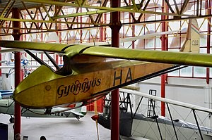
The new glider was named “Osoaviajimoviets JAI” (Russian: ХАИ Осоавиахимовец ХАИ).

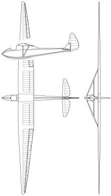
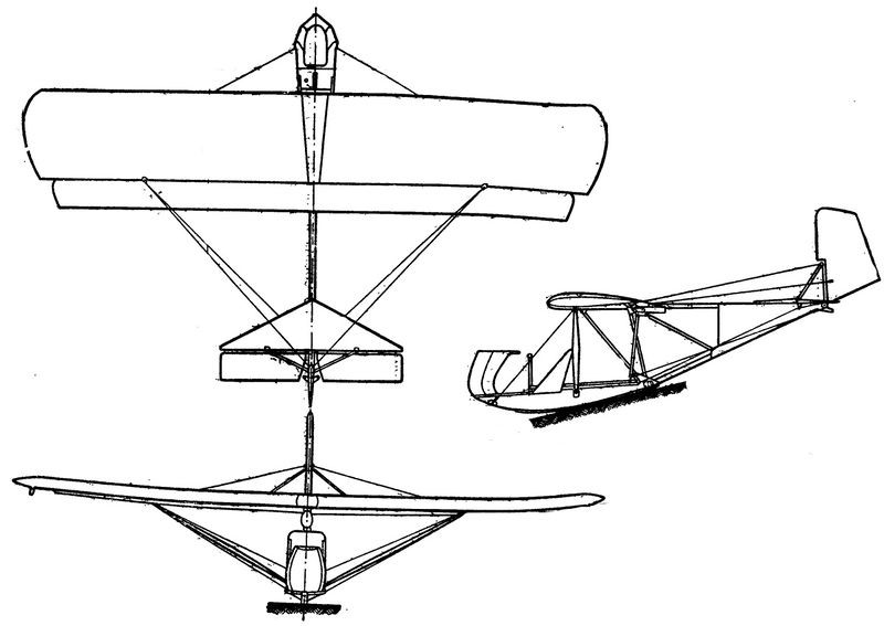
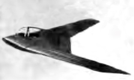
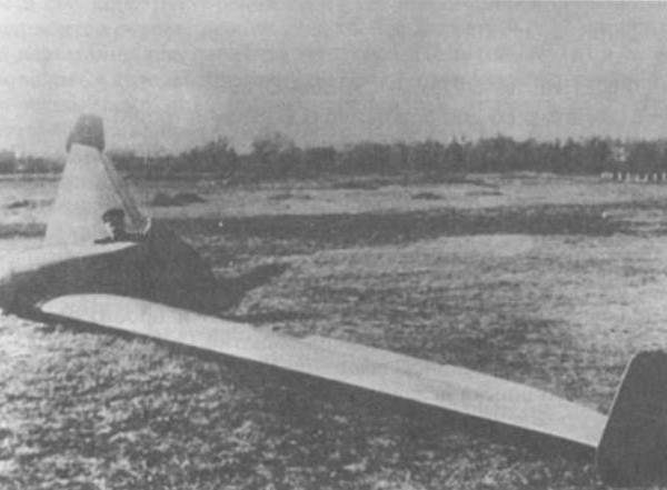
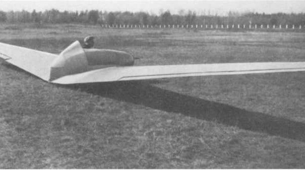
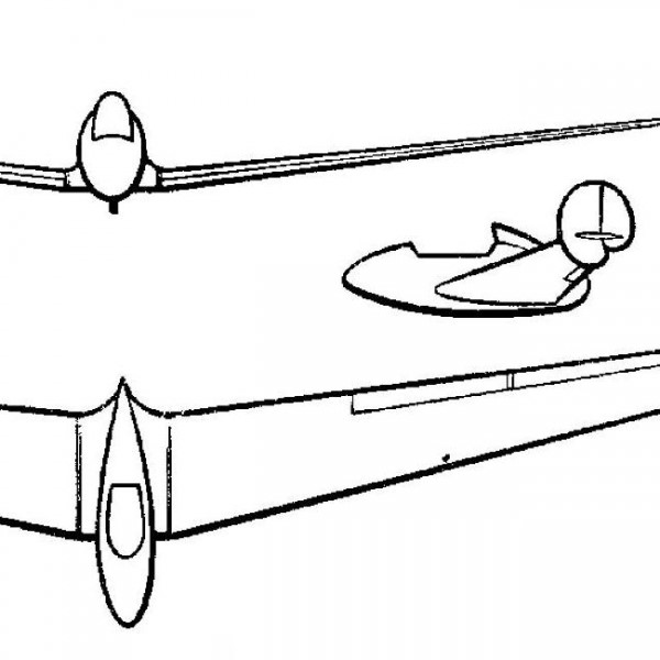
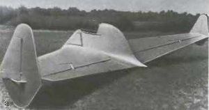
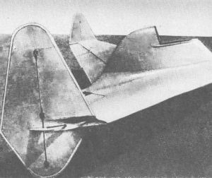
The “Osoaviajimiviets JAI” was designed as a single-seater glider in a tailless flying wing configuration. The construction was of wood with plywood coating.

The wing exhibited sagging and ended in vertical surfaces that included the aerodynamically compensated rudders.

The wing trailing edge featured full-span control surfaces that could perform the function of operating as ailerons or flaps.

On the longitudinal axis was the open cockpit for the pilot, with an aerodynamic fairing that made a smooth transition to the center plane.

A central wooden ski was used as the landing gear, supported by small skids under the vertical planes of the wing tip.

The project and plans for the tailless monoplane glider were ready in July 1933. Constructively it differed from the projected plane in its lower dimensions, the absence of an engine and landing gear. During the landing, an ash ski placed in the lower part of the apparatus was used. The cabin lantern was removable and made of celluloid.

The construction was sponsored by the Osoaviajim of the Ukrainian Soviet Socialist Republic, hence the name finger to the glider. The glider was designed by Bening and its construction began at the Kharkov Photomusical Factory in late 1933. Among the group of carpenters and cabinetmakers, M. Lass, AP Glinski and Grebenyuk stood out among others. When construction was at 90% completion, the decision was made to move it to the GVF Aviation Repair Shops in Kharkov (JARM), located in Sokolniki.

Once the “Osoaviajimoviets JAI” was finished, it was transferred to the JARM track.

On the 6 of February 1934 the first flight took place with BN Kudrin controls. After being launched with the use of an elastic band, the flight passed without great difficulties.

The first tests showed the excellent stability of the device in the air, but they must have been suspended as the weather conditions worsened. Only in May could they be continued by the pilot LS Ryzhkov. Originally, six roll-off flights were developed with takeoffs with elastic bands, in which heights of 10 meters and distances between 200 and 300 meters were achieved, making some small turns.

When the stability of the plane became evident, it was approved to carry out towed flights, originally from a car and later using a Polikarpov U-2. Sharp turns, dips, and reversals were tested on these flights. Subsequent flights were developed with towing from a Polikarpov R-5 at altitudes between 1,100 and 1,500 meters.

In mid-May, Ryzhkov managed to complete 26 closed loops in the “Osoaviajimoviets JAI” of which one started in the opposite direction, after the pilot inverted and made a 180º turn.

These manoeuvres were observed by members of a delegation from the Academy of Sciences of France led by J. Perren academic. Professor Gross, a member of the delegation, declared that the new tailless glider was a brilliant achievement of Soviet technique.

The glider also performed eights and combat evolutions, spinning and landslides. The diameter of the turns of the dead loop did not exceed 8 – 10 meters, the radius of the turns about 8 meters, the spirals 5 – 6 meters, which was quite difficult even for sports aircraft.

The tests demonstrated the excellent stability of the glider, its good response to the controls and the simplicity of the handling. It was also shown that the glider wing had a large reserve of strength, so the future JAI-4 was lightened.

In August 1934 the “Osoaviajimoviets JAI” was shown at the 2nd International Exhibition in Copenhagen and in September in Paris.

The model would be continued in the two-seater “PP Postyshev” or JAI-2.

Wingspan: 10.9 m
Wing area: 22 m²
Length: 3.75 m
Height: 1.1 m
Accommodation: 1