LiteCraft Bearcat

The Bearcat is a high-performance, rigid-wing, amateur-built aircraft with an all-steel 4130 chrome-moly (linseed oil flushed) fuselage frame that provides a tremendous amount of pilot protection and is resistant to vibration and rough-field conditions. This feature will increase the airframe life expectancy over the current aluminum tube airframes found on most ultra-light-type amateur-built aircraft, the company says. The tractor engine mounting and the 4130 chrome-moly bungee shock-absorbing landing gear are capable of absorbing impact in the event of an accident. The standard Bearcat is powered by a 42-hp Rotax 447 engine with the gear-drive reduction unit for a lightweight but efficient power package. The engine will produce 340 pounds of static thrust turning a 68 x 28 propeller. The airframe will accept engines of up to 65 hp. Another high-performance design feature incorporated in the Bearcat is the full-span trailing edge flaperons. The flaperons will be operated as flaps by lever and at the same time be operated as ailerons. When extended up to 40 degrees of, flaps, the wing will exhibit a higher lifting capability, decreasing the takeoff roll and increasing the climb capabilities. Flaperon extension will also create a downdraft on the spray pattern on the AG version to ensure better crop penetration of chemical. The airframe is stressed for +6 and -4 G’s.

Powerplant: Rotax 447 42 hp @ 6450 rpm.
Propeller: 66 x 28 wood.
Length: 17 ft 6 in.
Height (ft): 6.
Wingspan (ft): 30.
Wing area (sq.ft.): 150.
Wing loading (lbs/sq.ft.): 3.8.
Seats: 1.
Empty weight (lbs): 275.
Useful load (lbs): 300.
Maximum takeoff weight (lbs): 575.
Fuel capacity (USG): 5 (10 opt.).
Takeoff roll (ft): 150.
Takeoff over 50-foot obstacle (ft): 650.
Rate of climb (fpm): 800.
Max cruise speed (mph): 70.
Landing roll (ft): 150.
Landing over 50-foot obstacle (ft): 350.
Best rate of climb (mph): 40.
Design speed (mph): 55.
Never exceed (mph): 90.
Stall, power off (mph): 28.
Landing approach speed (mph): 35-40.
Optional equipment: Instrumenta¬tion, wheel fairing, brakes, floats.

Lischak Mobil Racer LW02

Willy Lischak of Bad Vosslau, Austria, designed and built the wood and foam Mobil Racer LW02.

On 21 June 1986 Lischak set two class C-1.A/O Group 1 (for aircraft under 661 lb) world records.
Distance in a closed circuit – 932.72 miles
1000 km closed circuit speed – 106.52 mph

On 24 May 1987 he upped both records to 1032.2 miles and 116.292 mph.

Engine: Steyr-Puch 751cc, 26 hp at 4000 rpm
Wing span: 17.71 ft
Length: 14.43 ft
Empty weight: 352.72 lb
Gross weight: 661.37 lb

LISA Airplanes Akoya

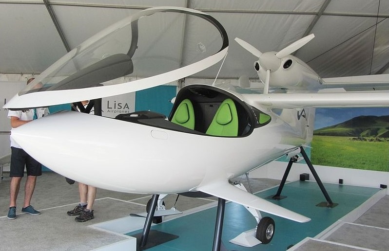
The LISA Akoya (Akoya is a species of pearl oyster) is a light aircraft designed to operate from land, water or snow without adaptation and incorporating a wing of variable area.

First flying on 22 August 2007 the LISA Akoya is a French single-engine light aircraft, seating two in side-by-side configuration. It is an amphibious aircraft capable of alighting on land, water or snow without adaptation. It has a high-aspect-ratio electrically-folding wing, with trailing edge extensions rather than flaps, and a rear-mounted tractor configuration engine.

Some other features are unusual: it has a wing which folds for transportation by horizontal rotation through almost 90° and a single engine mounted high on the fin in tractor configuration. It is built entirely from carbon-fiber-reinforced polymer composites.

The cantilever wings of the Akoya have an aspect ratio of about 18:1, they have constant chord apart from the angled tips. Instead of conventional hinged flaps, the inner 2⁄3 of the trailing edge can be extended rearwards, exposing new fabric surface stored within the wing in roller blind fashion. Fully extended for landing and half extended for take-off, these surfaces provide a large increase in wing area. Conventional ailerons are fitted outboard. High mounted, the wings attach at a rotatable fairing on the highest point of the fuselage, allowing the rotation for storage.

The fin and rudder together form a swept, short and parallel chord surface which carries at its top both the tailplane in T-tail configuration and the engine. The tailplane, like the wing, is of high aspect ratio and has full span elevators. The engine is a 73.5 kW (98.6 hp) Rotax 912 ULS flat four, driving a three bladed tractor propeller.

The Akoya’s fuselage is pointed at the nose and almost circular at its greatest diameter. In elevation it has a curved underside and, above, the large one piece canopy over the side-by-side, dual control cabin forms an unbroken line with the fuselage. There is an electrically operated retractable undercarriage of the taildragger variety, with the main gear legs rotating backward and inwards into the fuselage, and the tailwheel arm rotating forward. All wheels have hydraulic brakes. Operation from water, without a planing bottom or floats, is performed undercarriage up on the round fuselage underside with the aid of a pair of fixed hydrofoils, called shark-fins, sharply tapered planes set at about 50° to the vertical just outboard of the mainwheels. Small tip floats are an option for better lateral stability on water. The Akoya, it is claimed by the manufacturer, can also land on snow, though skis are an option.

A full-size mock-up appeared at the Friedrichshafen Aero ’07 show in April 2007, and the prototype flew in August 2007 at Chambery. By May 2009 F-WURE had flown 150 hours and 50 orders placed. Production was initially expected by mid-2011.

In March 2012 the company was pursuing light-sport aircraft approval of the design to facilitate sales in the United States.

In July 2012 the prototype had flown its first passenger and has been exhibited at AirVenture 2012. LSA approval and the start of production was still pending. Also in July 2012, the company was placed in receivership for financial restructuring after existing investors were not forthcoming with additional funds.

By February 2013 a 75% controlling interest in the company had been purchased by the Heima Mining Company of China for US$20 million. The Heima Mining Company was to name its own chairman of LISA and planed to open two new production lines in France. The Chinese investment permitted finalizing the Akoya’s design for production.

In late 2014 the aircraft was priced “all inclusive” at 300,000 Euros. In July 2015 information about the aircraft was shown at AirVenture, and the price was indicated as US$330,000, and the company claimed about 100 orders.

In March 2017 it was announced that an updated second-prototype would fly in April 2017, it included a new retractable landing gear that would enable the aircraft to operate on water, land and snow.

The second prototype, Pre-Series 1, first flew in August 2017 and features revised fuselage fins, that are horizontal, instead of canted downwards. This change enabled shortening the main landing gear legs to improve cockpit visibility when taxiing.

Akoya
Engine: 1 × Rotax 912 ULS with 1:2.34 reduction gear, 73.5 kW (98.6 hp)
Propeller: 3-bladed
Wingspan: 11.00 m (36 ft 1 in)
Wing area: 6.70 sq.m (72.1 sq ft)
Length: 6.90 m (22 ft 8 in)
Height: 2.35 m (7 ft 9 in) including propeller
Empty weight: 400 kg (882 lb)
Max takeoff weight: 650 kg (1,433 lb)
Fuel capacity / normal: 70 l (18 US gal; 15 imp gal)
Fuel capacity / optional: 110 l (29 US gal; 24 imp gal)
Cruise speed: 210 km/h (130 mph, 110 kn) economical
Stall speed: 64 km/h (40 mph, 35 kn) flaps down
Never exceed speed: 290 km/h (180 mph, 160 kn)
Range: 1,250 km (780 mi, 670 nmi) at economical cruising speed without optional tank
Rate of climb: 5.2 m/s (1,020 ft/min) maximum
Seats: 2
Avionics: VHF, intercom, transponder. Two screen EFIS with emergency backup instruments

Lippisch Wien

To remain competitive with the latest designs coming from the German universities, Robert Kronfield asked Alexander Lippisch, the Professor’s designer, for an improved version with better performance and handling. Lippisch’s response was an elegant sailplane that Kronfeld named Wien after his home town. The Wien kept the layout of the Professor, with pylon-mounted single-spar wings braced with faired struts, but the span was increased by 3.0 m (9 ft 10 in), raising the aspect ratio from 14 to 19.6. The fuselage was redesigned to have a smooth ovoid section, finer aft than on the Professor and fitted with a more aerodynamically refined fin and rudder.

Both designs used a plywood-covered D-box forward of the spar, with fabric covering behind, and their 2.50 m (8 ft 2 in) half span, parallel chord inner wing panels were similar, though close to the fuselage the Wien’s wing was strengthened with full chord plywood skin. The V-form bracing struts linked the extremes of these panels to the lower fuselage. The extra span of the Wien was in the double straight-tapered outer panels, which continued out to finer, rounded tips. Ailerons occupied the whole trailing edge of these sections.

The Wien’s open cockpit was ahead of the wing leading edge. There was no windscreen, and the instruments, including the still novel variometer, were displayed horizontally, inset into the fuselage immediately in front of the pilot. The undercarriage consisted of a single enclosed skid and a small spring tailskid. The rear fixed surfaces, ply covered, were very narrow, though the root of the fin was carefully faired into the fuselage. The tapered control surfaces were fabric covered.

The Wien was capable of utilizing both ridge lift and thermals. Kronfield used both methods in a series of ground breaking and often record setting flights between 1929 and 1931, learning much about thermal flying. On 15 May 1929 he made the first glider flight of more than 100 km (62 mi), largely ridge flying but with some thermal soaring. This was followed by at least three world distance records, the last between the Wasserkuppe and Marktredwitz, a distance of 164 km (102 mi) flown on 24 August 1930. Some very significant though not record breaking flights of about 160 km (100 mi) were made in August 1931 which used thermals alone and showed that on some days the distance that had to be flown between thermals was short. This was new information which, as it became widely known, opened up the potential of cross-country soaring.

Kronfeld also set two glider altitude records, the second flown on 30 July 1929 in thunderous conditions to a height of 2,560 m (8,399 ft).[2] At the invitation of the British Gliding Association he and the Wien made a series of demonstration flights on a tour of England in the Summer of 1931. During it he flew over London along the Thames and also won a £1,000 prize donated by the Daily Mail for a cross Channel flight. The North -South crossing, followed by a return flight, was made in July 1931; these did not use thermals but were direct glides from about 3000 m (9,840 ft) after an aero-tow.

Wingspan: 19.10 m (62 ft 8 in)
Wing area: 18.6 m2 (200 sq ft)
Aspect ratio: 19.6
Airfoil: Root, Göttingen 549 modified with thickened nose and increased camber
Length: 7.95 m (26 ft 1 in)
Empty weight: 158 kg (348 lb)
Gross weight: 248 kg (547 lb)
Wing loading: 13.8 kg/m2 (2.8 lb/sq ft)
Crew: One

Lippisch 272 Fafnir

Günther Groenhoff demonstrated his skill and courage while conducting research for a Munich meteorology conference in May 1931. On a mission to gather weather data, he installed various instruments on his Alexander Lippisch built “Fafnir” model 272 glider and was towed to altitude by a powered aircraft piloted by pilot Peter Reidel. As they approached towering cumulus clouds over Munich, Groenhoff’s Fafnir was released to his fate. For the next eight hours, he was bounced and buffeted around the thunderstorm amid lightning flashes, hail and torrential rain, all the while collecting valuable information on weather conditions. Many times he flew in the blind. His journal indicates that he experienced one rapid descent in zero visibility to emerge from the cloud to see the ground only a few hundred feet below. He managed to bank and return to the front side of the thundercloud. He wrote, “as soon as the storm reached me, some powerful force pulled the plane straight up into the center of the clouds. It seemed to me as if I were riding an express elevator of a high skyscraper.”
After soaring with the storm for eight hours, he had traveled 240 miles and finally landed on a riverbed, coming to rest a few meters short of an electric line near Kaaden, Czechoslovakia. Groenhoff wrote that he was gratified that he was able to bring home “the rich material for meteorological research.”
Back at Wasserkuppe on July 23, 1932, Groenhoff once again soared into the strong, turbulent winds of a thunderstorm. However, his good fortune had run out. The rudder of his Fafnir snapped and he crashed on the west slope, dying instantly. He was 23 years old.

Lippisch Delta 1

By 1931 Alexander Lippisch had progressed to a triangular wing form which he called ‘delta’, and his Delta 1 was ready for demonstration to top German aviation ministry officials at Berlin’s Templehof airport. The test pilot, Gunther Gronhoff, performed a low level aerobatic routine (even spinning the 30 hp Bristol Cherub powered delta), they remained unconvinced. Lippisch would not get an airworthiness certificate, they declared, until he put tails on his aircraft.

Lippisch DM-1

During World War II, Dr. Alexander Lippisch proposed a ramjet propelled point defence fighter, the Lippisch P.12/13a. It was a sharply-swept delta flying wing with the engine buried the a thick, blunt-nosed wing. The pilot was accommodated in the forward section of the tail fin, which was as thick as the wings and almost as large. A scale model was successfully flown at Spitzerberg, near Vienna.

Lippisch himself lost interest in the design and began work on the P.13b with a different wing, but he was approached by students of Akaflieg Darmstadt and Akaflieg München, who asked for vital war work so that they would not be drafted. By this time in 1944 Lippisch realised that the war was hopeless and was happy to oblige, arranging for them to build a full-scale aerodynamic test glider for the P.12/13a project.

Construction was begun at the workshop of the Akaflieg Darmstadt, as the Darmstadt D-33. The workshop was bombed in September 1944, so the part-built airframe was moved to the Akaflieg München workshops at Prien am Chiemsee, where it was redesignated the DM-1 (for Darmstadt-München 1). At Prien, Wolfgang Heinemann and Hans Zacher from Darmstadt, with Klaus Metzner and Hermann Nenninger from Munich, continued the work.

The DM1 was a single-seat glider made from steel tubing, plywood and bakelite impregnated plywood. The cockpit canopy was integrated into the fin leading edge. Launching the DM-1 was to be by piggy-back or aero-tow.

After occupation by U.S. Troops in May 1945, work continued at the DM-1 on behalf of the U.S. military government, with General Patton and Charles Lindbergh visiting Prien to see the project.

The DM 1 at Munich Prien airport after the war

Completed in early November 1945, the DM-1 was shipped in a wooden box to Langley Field in Virginia where the flow behaviour of the DM-1 was examined in the NACA (National Advisory Committee for Aeronautics, forerunner of today’s NASA) full-size wind tunnel.

When tested at Langley, the DM-1 was found to perform poorly. It generated significantly less lift at low speeds than small-scale models had suggested. The cause proved to be vortex lift generated by the models which, due to its much higher Reynolds number, the full-size aircraft did not produce.

The DM-1 modified for wind tunnel testing by NACA.

As a consequence it underwent a programme of modifications. Like all Lippisch deltas it had a thick wing with a blunt leading edge. A strip was fixed along the leading edge to simulate a sharp profile. This created the vortices seen on the model and greatly increased the lift. The origin of modern vortex lift theory may thus be traced to the NACA study and the modified DM-1.

The large and even thicker vertical stabilizer was removed and replaced with one of much smaller size, along with a cockpit canopy from a Lockheed P-80 Shooting Star in a more conventional position. Together with improvements to the elevon hinges, this significantly reduced overall drag.

After completion of testing the DM-1 was retired to the National Air and Space Museum, Smithsonian Institution in Washington, D.C. for storage at the Paul E. Garber Preservation, Restoration, and Storage Facility.

Lippisch DM-1 in restoration at the Smithsonian

Besides the NASA modifications, the Akafliege Darmstadt and München defined some powered designs for a development programme derived from the DM-1.
DM-1 (Lippisch). Glider as originally built but never flown, with thick wings and large tail.
(NACA). Glider as modified with leading-edge strip, small thin fin, conventional cockpit and sealed elevon hinges.
DM-2. Larger, supersonic test plane with 8.5 metres (27 ft 11 in) span, 8.94 metres (29 ft 4 in) length and prone pilot. Powered by a Walther liquid-fuelled rocket. All-up weight 11,500 kilograms (25,400 lb).
DM-3. Developed version of the DM-3 with pressure cabin and more powerful Walther C engine.
DM-4. Engine flight testbed, initially fitted with a Walther C. Airframe weight (without engine) 2,500 kilograms (5,500 lb)

DM-1
Wingspan: 6 m (19 ft 8 in)
Wing area: 19 m2 (200 sq ft) ca
Length: 6.32 m (20 ft 9 in)
Height: 3.25 m (10 ft 8 in)
Empty weight: 375 kg (827 lb)
Gross weight: 460 kg (1,014 lb)
Maximum glide ratio: 7
Crew: 1