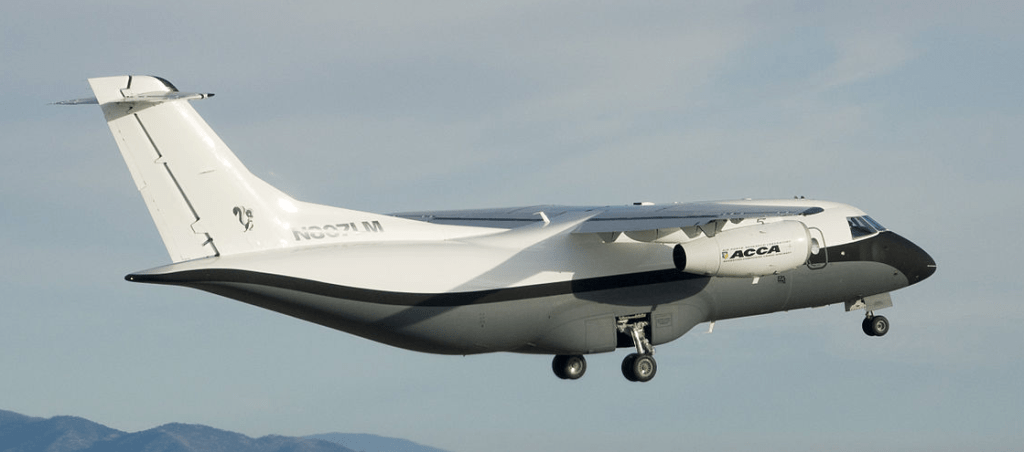
The Lockheed Martin X-55 Advanced Composite Cargo Aircraft (ACCA) is an experimental twinjet transport aircraft. It is intended to demonstrate new air cargo-carrier capabilities using advanced composite materials. A project of the United States Air Force’s Air Force Research Laboratory, it was built by the international aerospace company Lockheed Martin, at its Advanced Development Programs (Skunk Works) facility in Palmdale, California. The X-55 is a one-off aircraft intended to demonstrate the use of advanced composite materials in the fuselage of an otherwise conventional high-wing transport aircraft.
The aircraft is powered by two Pratt & Whitney Canada PW306B turbofans. The X-55 design is based on the existing Fairchild Dornier 328JET. The fuselage of that aircraft, which is constructed of aluminium alloys, was replaced aft of the entrance door with a newly designed fuselage. The new design makes extensive use of advanced composite materials, selected to allow out of autoclave curing at lower temperatures and pressures than previous materials. The new widened fuselage allows the loading of cargo through a rear ramp.
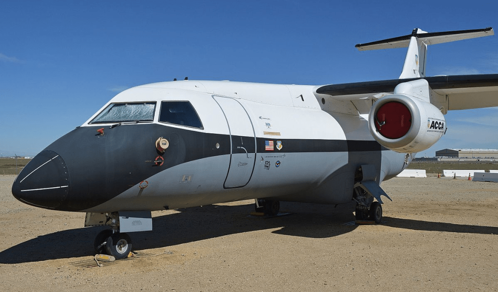
The new fuselage section is constructed as a single large component, including the vertical stabilizer. When attached to the existing nose section, the fuselage is 55 feet (16.8 m) long and 9 feet (2.74 m) diameter. The fuselage has upper and lower halves, each with a roughly-oval shape similar to a canoe. The halves are bonded to circular frames. The fuselage section ahead of the entrance door consists of the existing (metal) 328J component, with fasteners used to bring the forward and new aft sections together.
As of April 2008, the fuselage was being fabricated. The first flight of the modified aircraft was expected during the winter of 2008/2009. However, due to a “glitch” during fabricating the composite fuselage, that schedule slipped. The delay was caused by an unsatisfactory bond of the skin on the lower fuselage, which required a second fuselage to be fabricated.
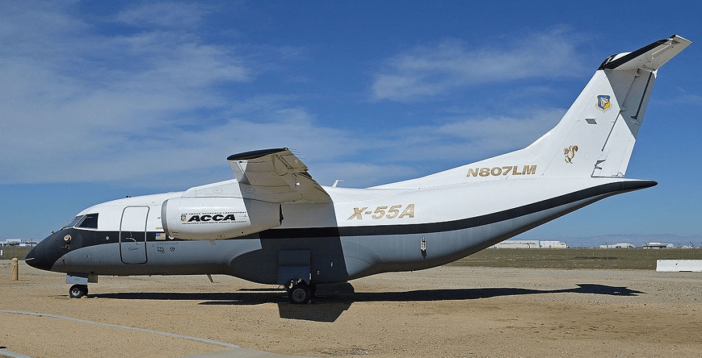
The first flight was completed at Lockheed Martin’s Advanced Development Programs facility (Air Force Plant 42) in Palmdale, California on June 2, 2009 by the Air Force Research Laboratory in conjunction with Lockheed Martin. In October 2009, the ACCA demonstrator was designated X-55A by the USAF. Over the course of the program, 15 to 20 flights were expected.
As of September 12, 2014, the X-55 aircraft is on display at the Joe Davies Heritage Airpark in Palmdale, California.
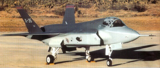
The X-35 was the Lockheed Martin Joint Strike Fighter (JSF) demonstrator, competing with the Boeing X-32. In November 1996 Boeing and Lockheed Martin were awarded contracts to build two Concept Demonstrator Aircraft (CDA)—one Conventional Take-Off and Landing (CTOL) version and one Short Take-Off and Vertical Landing (STOVL) version—each. The aircraft were not intended to be fighter prototypes, but rather to prove that the selected design concepts would work, hence the use of X-series designations.
Lockheed constructed two prototypes for the evaluation. The initial X-35A reflected the basic Air Force CTOL design, and was used for early flights before being modified into the STOVL version, designated X-35B. While Boeing proposed a direct lift STOVL design based on that used in the Harrier, Lockheed opted for a different approach in meeting the vertical flight requirements. Inspired by the Russian Yak-141, the X-35B incorporated a separate lift-fan that was shaft-driven by the F119 engine, allowing cooler exhaust temperatures during hover. While the Boeing design was more conventional, Lockheed argued that their strategy was better in the long term since it offered more room for growth as the aircraft evolves. The second airframe was the X-35C STOVL demonstrator for the Navy. This model featured an enlarged wing of greater span and area for larger fuel capacity as well as enlarged horizontal tails and flaperons for greater control effectiveness during low-speed carrier approaches. The X-35 was selected as the winner of the JSF competition on 26 October 2001.
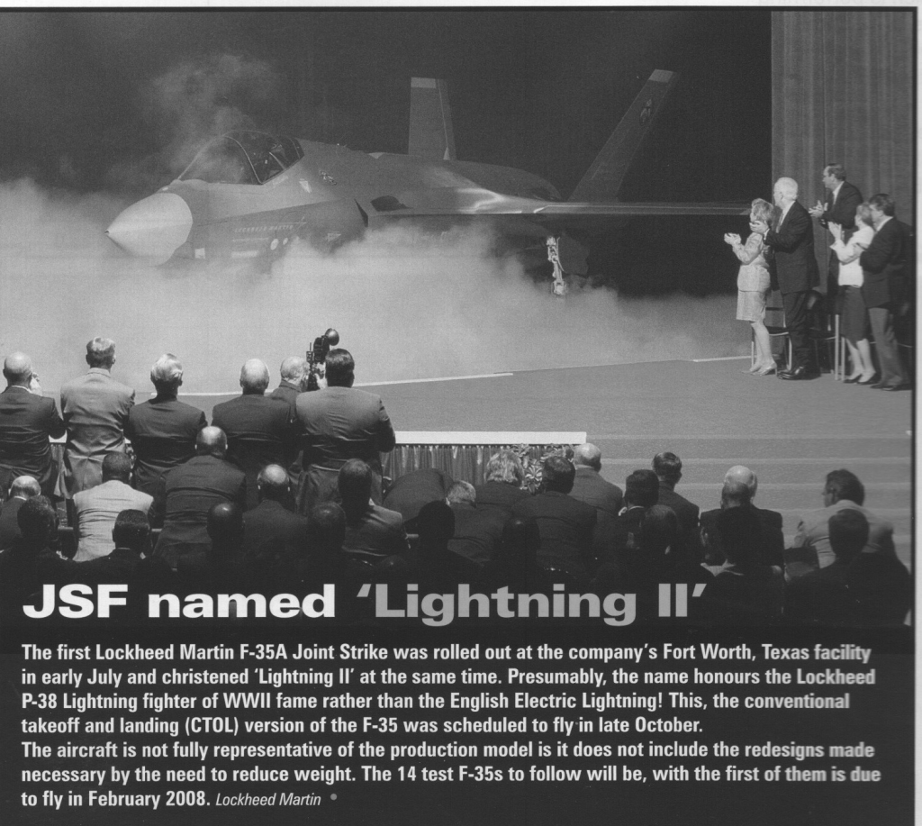
The production aircraft to be designated F-35. The System Development and Demonstration (SDD) phase of the F-35 JSF program started with the signing of the SDD contract in October 2001, and with the delivery of test aircraft scheduled to begin in 2008. During the SDD phase, 22 aircraft (14 flying test aircraft and 8 ground-test aircraft) were to be produced and tested. The JSF program is slated to produce a total of 3,002 aircraft for the United States and United Kingdom armed forces.
Lockheed Martin leads a development team including Northrop Grumman, BAE Systems, and Pratt & Whitney. Lockheed Martin brings in advanced technology experience, stealth technology and other technologies and experience which it has gained during F-22 research and development. Northrop Grumman offers tactical aircraft knowledge, stealth technology and carrier suitability. BAE System provides expertise and experience with short take off and vertical landing (STOVL) technology as well as advanced subcontract management. Pratt & Whitney is the builder of the engine which will power the JSF which is based on the F-119 turbojet from the F-22.
To forfill the demands of the main contractors three different variants are developed. All versions will have a common structure and have the same fuselage and internal weapons bay. They will all three be powered by a F-119 modified engine. All variants will carry the standard designation F-35.
The F-35A is the standard variant with conventional take off and landing developed for the US Air Force, the biggest JSF customer. The F-35A will replace the F-16 and the A-10 aircraft currently operated by the USAF.
X-35B
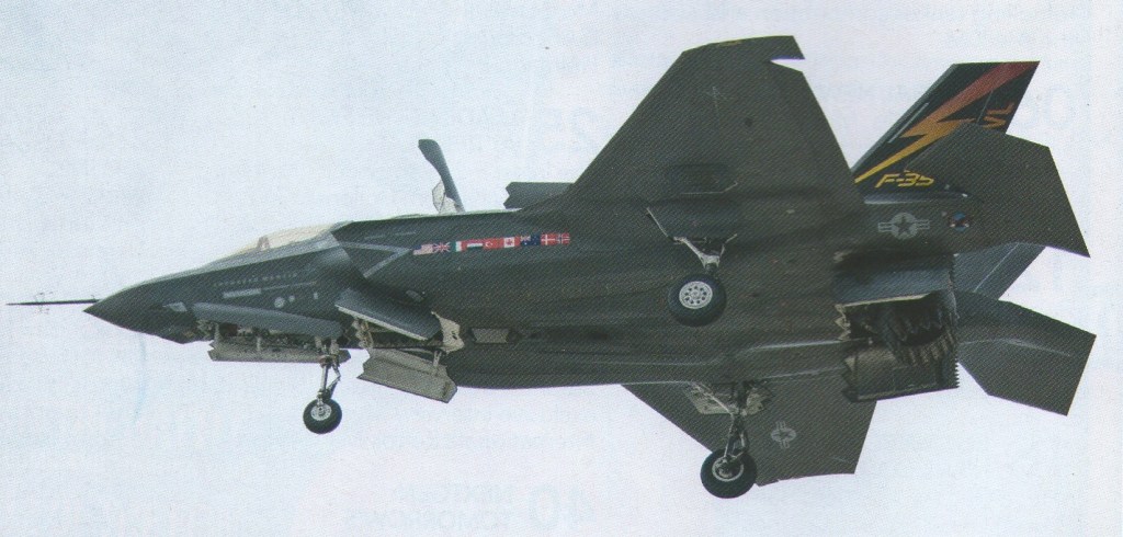
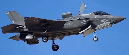
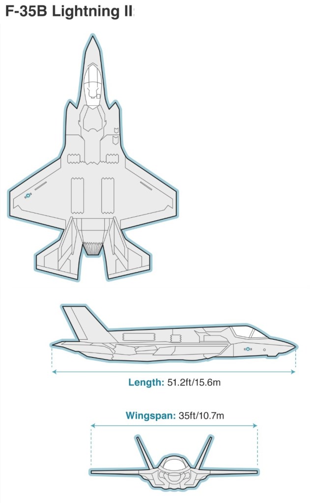
The F-35B is the STOVL variant of the JSF. The F-119 is modified using the experience of BAE Systems based on the Rolls-Royce Pegasus engine from the AV-8 Harrier. Unlike the Air Force variant the F-35B carries no internal gun and the air refuelling probe is located on the right side of the forward fuselage instead of receptacle on the top surface of the aircraft. The main customers for the F-35B will be the USMC to replace the F/A-18 Hornet ands the AV-8B Harrier IIs and the United Kingdom to replace the Royal Air Force/Royal Navy combined Harrier force of Sea Harriers and GR.7s.
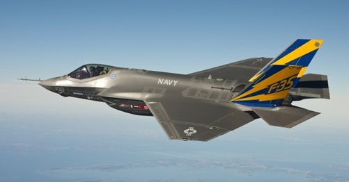
The F-35C is a modified design which enables the JSF to operate from aircraft carriers using conventional carrier landings and catapult take off. The F-35C internal structure and landing gear have been strengthened to handle the loads associated with catapult launches and arrested carrier landings. It has a larger wing area than other JSF types with larger control surfaces for better low speed handling. Like the F-35B is has a refuelling probe instead of a receptacle. The US Navy will be the biggest customer of this variant. The F-35C will complement the US Navy fleet of F/A-18E/F fighters by replacing the F/A-18 A+ and C Hornet in service.
Lockheed Martin F-35B Lightning II BF-3 – the third example of the short takeoff/ vertical landing version – arrived at NAS Patuxent River, Maryland on February 17, 2010. It made its first flight on February 2 at Fort Worth, Texas and was taken from there to the naval air station by F-35 Test Pilot Jeff Knowles. Another two F-35Bs are due to join the three aircraft at Patuxent River for the flight test programme.
The F-35B was about to conduct its first vertical landing which would be a major milestone for the short take-off, vertical landing (STOVL) variant and work has started on the first F-35 lightning II for the UK.
The Lockheed Martin X-35C Joint Strike Fighter (JSF) Navy demonstrator completed medium-speed taxi testing Dec. 14 2000 at Palrndale, California, in preparation for first flight as early as Dec. 16. The aircraft, with a larger wing and control surfaces than the X-35A, will undergo about 20 hr. of flight test at Edwards AFB, before being flown to NAS Patuxent River, Md., for the continuation of demonstrations. Meanwhile, Boeing has completed structural mode interaction testing on the X-32B short takeoff and vertical landing demonstrator, expected to fly during the first quarter of 2001. The Boeing X-32A demonstrator completed government-required Navy demonstrations Dec. 2, 2000.
First flown on 24 October 2000, the JSF X-35A demonstrator aircraft completed a highly successful flight-test programme in August 2001, and the following October the US Government awarded its development contract to Lockheed Martin over the other contender, Boeing. The lift system uses a counter-rotating lift fan, located behind the cockpit and connected to the engine by a drive shaft, as a primary lifting force. The fan produces more than 18,000 lbs of cool thrust in hover flight, with an additional 18,000 lbs coming from the main engine’s vectored aft nozzle and wing roll-posts. The shaft driven Rolls-Royce lift fan amplifies engine thrust and reduces exhaust temperature and velocity during STOVL operations. First flown on 24 June 2001, in 2001 the X-35A, reconfigured as the STVOL X-35B, achieved its first vertical take-off, level supersonic flight, and vertical landing. The X-35C is to evaluate manoeuvering qualities, as a conventional carrier version and first flew on 16 December 2000. This version has larger wing and control surfaces and is stressed for catapult launches and arrested landings. This wing could also be applied to the B or A version.
By March 2010, it appeared that just five F-35s had flown: F-35A AA-01 on December 25, 2006. F-35B BF-0 1 on June 11, 2008. F-35B BF-02 on February 2, 2009 F-35A AF-01 on November 14,2009 F-35B BF-03 on February 2, 2010
The first F-35A has since been retired from flight duty. Two of the three F-35Bs were at Naval Air Station Patuxent River, Maryland, for preliminary STOVL evaluation tests.
The first pre-production F-35A flew on 15 December 2006, about three months behind schedule due to engine integration and ground testing delays.
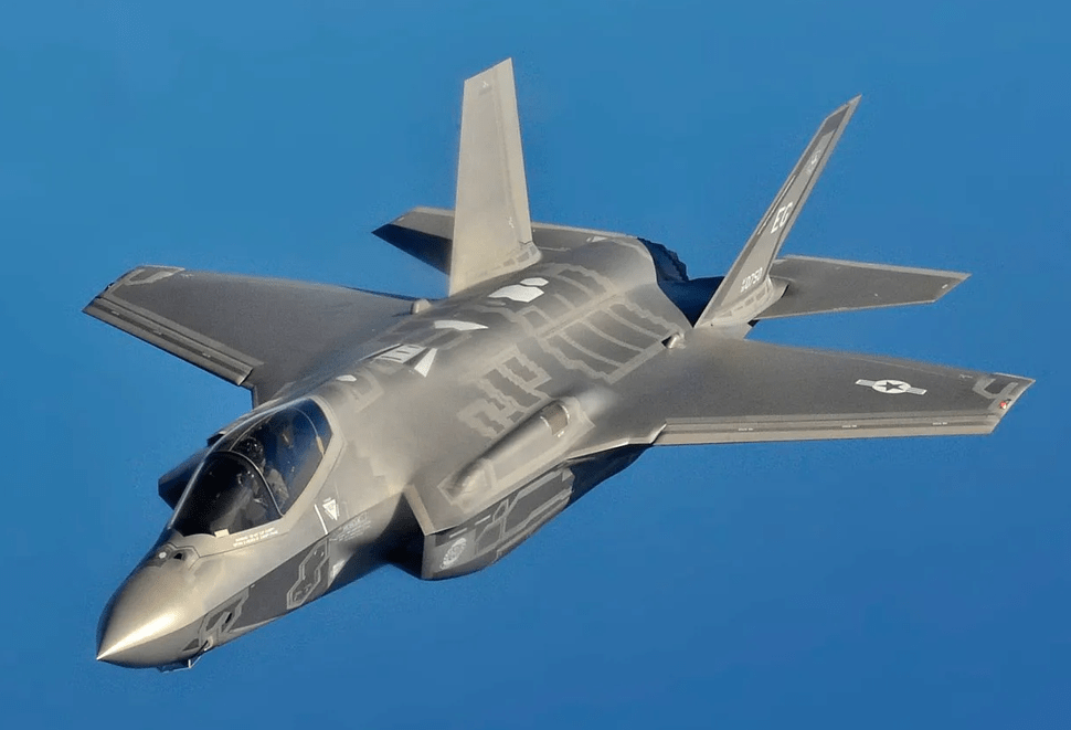
F-35 Lightning II
As of 2014, 115 have been built at $106,000,000 each.
With over 1,000 aircraft delivered to 17 nations, including Australia, Israel, Japan, South Korea, and multiple NATO allies, and production plans exceeding 3,000 units, the F-35 represents the standardisation of fifth-generation technology across Western and allied air forces.
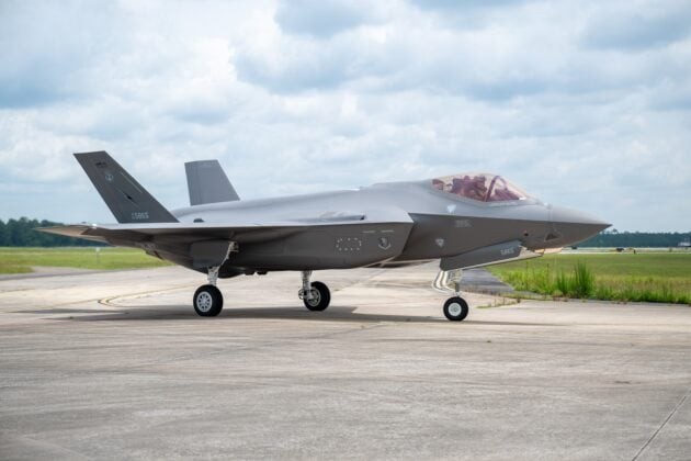
The U.S. Air Force’s 500th F-35A Lightning II fighter jet arrived at the Florida Air National Guard’s 125th Fighter Wing in Jacksonville on July 9, 2025.
500th USAF F-35A Lightning II
The aircraft is one of the first three F-35As permanently assigned to the wing, known as “the Thunder,” and features the unit’s legacy tail flash. By the end of 2024, Lockheed Martin had delivered a total of 1,102 aircraft. That figure included 797 F-35As built for the United States and allied air forces, along with 203 short takeoff and vertical landing F-35Bs built for the U.S. Marine Corps, the Royal Navy, the Royal Air Force, and the Italian Navy. The first examples for Japan’s Navy are also in production and delivery. According to F35.com, more than 1,215 F-35s of all variants have now been delivered worldwide, flown by over 3,000 pilots who have accumulated more than one million flight hours.
In the late 1970s, the US Air Force identified a requirement for 750 examples of an Advanced Tactical Fighter (ATF) to replace the F-15 Eagle. Flown by a single pilot, it must be able to survive in an environment filled with people, both in the air and on the ground, whose sole purpose is to destroy it. To test the concepts that would eventually be combined in the ATF, the US AF initiated a series of parallel research programmes. The first was the YF-16 control-configured vehicle (CCV) which flew in 1976-77 and demonstrated the decoupled control of aircraft flight path and attitude; in other words, the machine could skid sideways, turn without banking, climb or descend without changing its attitude, and point its nose left or right, or up or down, without changing its flight path. Other test vehicles involved in the ATF programme included the Grumman X-29, which flew for the first time in December 1984 and which was designed to investigate forward-sweep technology, and an F-111 fitted with a mission adaptive wing (MAW) – in other words, a wing capable of reconfiguring itself automatically to mission requirements.
Flight testing of all these experimental aircraft came under the umbrella of the USAF’s Advanced Fighter Technology Integration (AFTI) programme. In September 1983, while the AFTI programme was well under way, the USAF awarded ATF concept definition study contracts to six American aerospace companies and, of these, two – Lockheed and Northrop – were selected to build demonstrator prototypes of their respective proposals. Each company produced two prototypes, the Lockheed YF-22 and the Northrop YF-23, and all four aircraft flew in 1990. Two different powerplants, the Pratt & Whitney YF119 and the General Electric YF120, were evaluated, and in April 1991 it was announced that the F-22 and F119 were the winning combination. The F119 advanced technology engine, two of which power the F-22, develops 155kN and is fitted with two-dimensional convergent/ divergent exhaust nozzles with thrust vectoring for enhanced performance and manoeuvrability.
The Raptor is designed and built by Boeing, Lockheed Martin and Pratt & Whitney. Boeing supplies the F-22s 2,000-lb titanium and composite wings and aft fuselage, integrates and tests the advanced avionics and is responsible for the training and life-support systems.
Previously the designation for the Raptor was changed to F/A-22 to indicate the possible air-to-ground role of the aircraft. JDAM bombs can be carried in the internal weapon bay, while the optional external pylons offer a more flexible station for air-to-ground armament. However the U.S. Air Force changed the designation back to F-22 in December 2005, although it will still posses the secondary air-to-ground role.
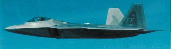
The F-22 combines many stealth features. Its air-to-air weapons, for example, are stored internally; three internal bays house advanced short-range, medium-range and beyond-visual-range air-to-air missiles. Following an assessment of the aircraft’s combat role in 1993, it was decided to add a ground-attack capability, and the internal weapons bay is also capable of accommodating 454kg GBU-32 precision-guided missiles. The F-22 is the first production aircraft with the ability to super cruise – flying at supersonic speeds without the use of afterburners. The F-22 is designed for a high sortie rate, with a turnaround time of less than 20 minutes, and its avionics are highly integrated to provide rapid reaction in air combat, much of its survivability depending on the pilot’s ability to locate a target very early and take it out with a first shot. The F-22 was designed to meet a specific threat, which at that time was presented by large numbers of highly agile Soviet combat aircraft, its task being to engage them in their own airspace with beyond-visual-range weaponry. It will be a key component in the Global Strike Task Force, formed in 2001 to counter any threat worldwide. The USAF requirement is for 438 aircraft.
The first definitive F-22 prototype was rolled out at the Lockheed Martin plant at Marietta, Georgia, on 9 April 1997.
The planned first flight of the F-22A, scheduled for 29 May 1997, was delayed by a small fuel leak in the F-1A tank just aft of the cockpit, together with an oil problem in the APU/auxiliary generator system area and software troubles.
The first flight was delayed to 7 September 1997. The second prototype first flew on 29 June 1998. The first two Raptor fighters, Nos. 4001 and 4002, have only 80% of the required strength, partly the result of an aggressive weight-cutting program, and the No. 4003 airframe has been strengthened to make it 100% capable. The third F-22 was delivered to Edwards AFB in March 2000. The aircraft was about eight months behind schedule. The empty weight is still low enough to beat the operational requirements. Raptor 4001 has been doing high speed tests such as loads and flutter but could not fully clear the envelope because of the lower strength, although it and ship No. 4002 have both exceeded 7g loads. The Air Force will only say that the required F-22 limit exceeds 7g. Raptor 4003 will provide full high speed clearance for subsequent aircraft, but will first spend several months on the ground at Edwards AFB because the reworked structure requires new ground vibration tests and other evaluations. The nonstop delivery from Marietta, Ga., was the fourth flight of 4003 and lasted 4 hr. 50 min., including four aerial refuelings. By late 2001, there were eight F-22s flying.
A YF-22 being tested at Edwards reacted unexpectedly when a go round initiated a changed in its fly-by-wire control laws. After a few cycles of PIO, the aircraft belly-flopped onto the runway.
In January 2003, the Air Warfare Center at Nellis Air Force Base near Las Vegas, Nevada, received its first Raptor. It was the twelfth F-22 produced. The 422nd Test & Evaluation Squadron took on seven more F-22s for testing and training of the initial cadre of instructor pilots. The 43rd Fighter Squadron became the first F-22 squadron when it received its first F-22 (then designated F/A-22) in the end of September in 2003. The unit of the 325th Fighter Wing carries out the training at Tyndall Air Force Base, Florida. In January 2004, the first pilot qualified at Tyndall AFB.
The 27th Fighter Squadron of the 1st Fighter Wing at Langley AFB became the first operational F-22 squadron when it received its first Raptor in January 2005. The squadron was declared operational (initial operational capability) in December 2005 with 12 F-22A Raptors. Also based at Langley AFB, the 94th Fighter Squadron received its first two Raptors in March 2006. On January 19, 2007, the last of 40 F-22A Raptor for the 1st Fighter Wing was delivered to the 94th FS, equipping both fighter squadrons with 20 Raptors each.
First prototype: N22YF (GE YF120 engines) rolled out at Palmdale 29 August 1990; first flight/ferry to Edwards AFB 29 September 1990; first air refuelling (11th sortie) 26 October 1990; Mach 1.58 supercruise’ (later exceeded) on 3 November 1990; first thrust-vectoring 15 November 1990; anti-spin parachute fitted for high AoA tests with thrust-vectoring; last flight 28 December 1990 — total 43 sorties/52.8hr.
Second prototype: N22YX (P&W F119 engine) first flight Palmdale-Edwards 30 October 1990; launched first AIM-9M Sidewinder on 28 November 1990 and AIM-120 AMRAAM on 20 December 1990; achieved Mach 1.8 26 December 1990; last flight 28 December 1990 — total 31 sorties/38.8 hrs. Summary demonstrated thrust vectoring, including 100deg/sec roll rate at 120kt (222km/h; 138mph); Mach 2 speed with afterburning. Aircraft in storage at Edwards AFB from January 1991.
Despite its $150 million unit cost and production run of only 195 aircraft, terminated early due to post-Cold Its capabilities were partially demonstrated during deployments to Syria, where Raptors operated with impunity even in airspace covered by advanced Russian air defence systems.
The F-22’s main limitation is its age—designed before modern networked warfare concepts were fully developed, it lacks some of the connectivity features of newer aircraft.
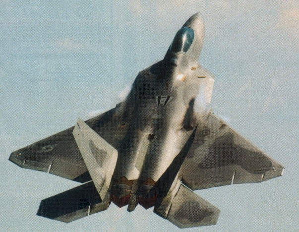
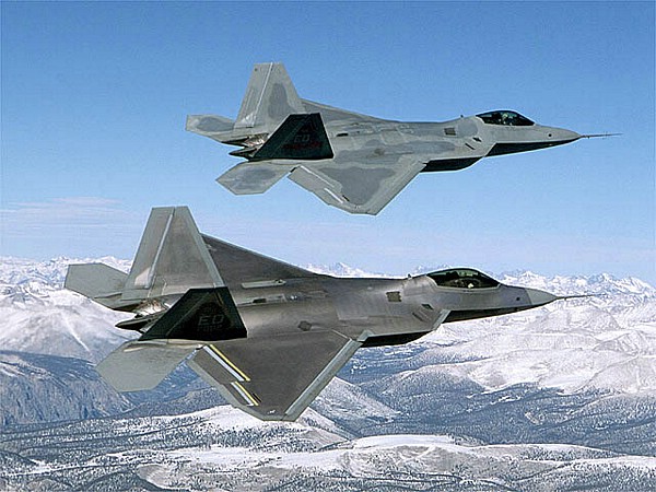
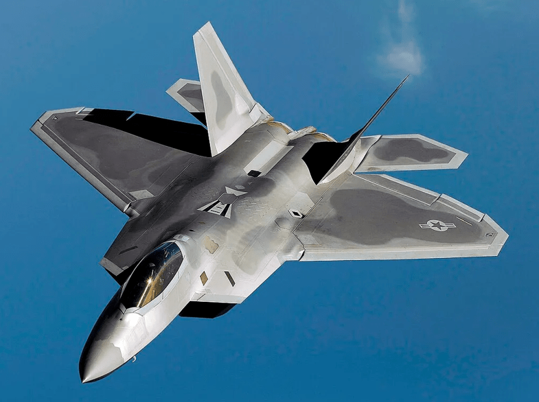
Lockheed Martin F-22 Raptor
However, ongoing modernisation programs including upgraded processors, new datalinks, and integration with the latest AIM-260 long-range missiles will keep the Raptor at the forefront of air combat capability until its planned replacement by the sixth-generation NGAD (Next Generation Air Dominance) fighter.
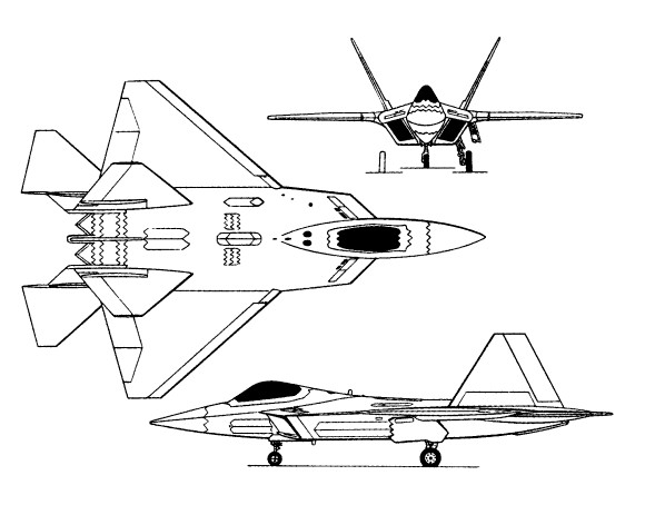
F-22A Engines: two Pratt & Whitney F119-P-100 turbofan, 155.69 kN (35,000 lb st) with afterburning Length 18.92m (62 ft 1 in) Height 5.00m (16 ft 5 in) Wing span 13.56m (44ft 6 in) Empty weight: 13.608+ kg (30,000+ lb) Max Take-Off Weight: 26.308 kg (58,000 lb) Max level speed at optimum altitude: Mach 1.58 in supercruise Max level speed at 30,000 ft (9145m) Mach 1.7 in afterburning mode Service ceiling: 15,240+m (50,000+ ft) G limit: +7.9 Armament: one 20mm M61A2 Vulcan six-barrel gun with 480 rounds; 2 AIM-9X Sidewinder IR-guided missiles in internal side bays. Up to 6 AIM-120C or 4 AIM-120A AMRAAM missiles in internal fuselage weapon bays or 2 AIM-120C AMRAAMs and 2 GBU-32 JDAM bombs or 2 GBU-30 JDAM bombs. Up to four fuel tanks and up to 8 missiles on optional external hardpoints.
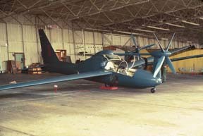
The Lockheed Brothers left the Company after the Detroit merger and set up the Airover Company, later called Alcor, to build the Uni-twin. With two Menasco engines side-by-side in the nose, driving two propellers. The name of the company was changed to Lockheed Vega when it became a subsidiary of the revived parent organization.
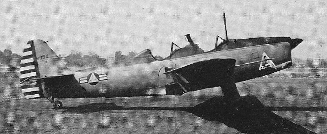
With Allan H. Lockheed as president, built a new version of his Duo twin-engined monoplane. Type was called Alcor Duo-6 and was distinctive in having two Menasco engines placed horizontally.
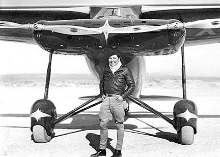
A demonstration flight was made in May 1934 at Mines Field with one propeller removed—it took off in 1200′, attained 130mph, and reportedly handled much like a single-engine plane.
Alcor Duo-6 NX962Y
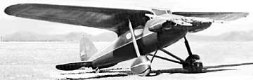
The Alcor Olympic Duo-4 of 1930 designed by Allan Loughead, featured two engines mounted side-by-side in a nose nacelle. Powered by two 160hp Menasco B-6 (reportedly first with 125hp C-5s), it was originally planned for one Wright J-6-7c in the nose. The unbraced cantilever wing had two full-length box spars.
Alcor Duo-4 with Pancho Barnes
The one five-place Alcor Duo-4 built, NX962Y, nosed over in a wind gust during a landing on Mar 18, 1931; although damage was slight, nervous financial backers withdrew their support.
Though Alcor conformed with Lockheed “star names” system and development was pursued in 1930s, no production resulted. Alcor was not a Lockheed Aircraft Corporation product.
Olympic Duo-6 Engines: two 230hp Menasco B-6S Wingspan: 42’0″ Length: 28’6″ Useful load: 2045 lb Max speed: 183 mph Cruise: 157 mph Stall: 57 mph Range: 700 mi
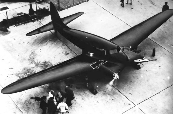
Around this time, the late 1930s Lockheed Aircraft Corporation was studying different airliner projects. The first was the Model 27, which had a canard configuration. The other two were the L-104 and L-105. The L-105 was smaller, with 1200 hp engines, and was more conventional than the L-104. These studies led Lockheed’s Burbank facility to settle on a design dubbed Model 44, a four-engined airliner that was announced to the public in April 1939. Soon afterwards, the new airliner was dubbed Excalibur. The Excalibur resembled an enlarged Model 10 Electra. It would be powered by four Wright GR-1820 Cyclone 9 radial engines, rated at 1000 hp (746 kW), or four Pratt & Whitney R-1830 Twin Wasp radials. Its wingspan was 95 ft 9 in (29.18 m), its length was 82 ft 6 in (25.15 m), and its projected maximum speed was in the 250-280 mph range (402–451 km/h). Several variants were proposed, to accommodate different passenger loads.
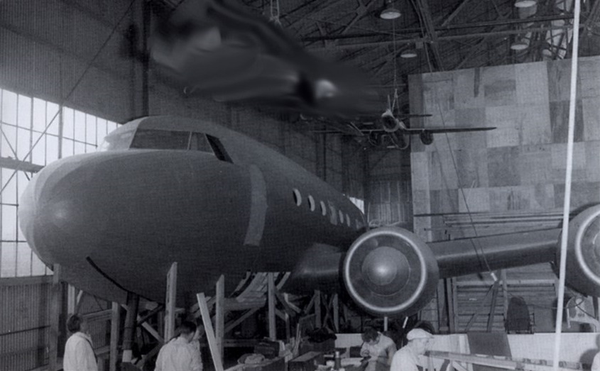
The original Excalibur design envisioned a 21-passenger payload, with a 240 mph (386 km/h) cruising speed. This was revised to 36 passengers at 268 mph (431 km/h) cruise at 12,000 feet (3,660m) altitude. This change included increasing the fuselage diameter, making it comparable to the Model 18 Lodestar, and increasing the wingspan to 95 ft 9 in (25.19 m) with an area of 1,000 ft² (92.9 m²). A tricycle landing gear with steerable nosewheel was envisioned. With the revised specifications, the Excalibur could now effectively compete with the near monopoly Douglas had on the airliner market. Its projected performance was better (except in range) than the Boeing 307. The revision of specifications was partially due to a request from Pan American Airlines; their influence also caused the addition of the third tailfin. A variant designated the L-144, able to carry 40 passengers was planned, but was ultimately cancelled even though South African Airways had placed a potential order for two examples. Lockheed proceeded with a full-scale mockup of the proposed Excalibur, including most of the airliner except the right wing.
The billionaire Howard Hughes, who had recently gained ownership of Transcontinental & Western Air (TWA), decided to provide funding for the new Excalibur. He had a plan in mind to vastly improve the characteristics of the Excalibur by increasing comfort, speed and profit of the aircraft. It was thus that Hughes invited three workers from Lockheed and Jack Frye (president of TWA) to a meeting at his Hancock Park residence. The Lockheed employees included Clarence “Kelly” Johnson and Robert E. Gross. Hughes expressed his requirements for the “airliner of the future”: a payload of 36 passengers (or 20 sleeping berths), a six-person crew, a 3,600 mile (5,800 km) range, a 300 mph (483 km/h) cruise speed, and a weight of 23.5-25 metric tonnes. This meant that the Excalibur would have to get a 100 mph (161 km/h) increase in speed and be able to fly 1,000 ft (305 m) higher. It would need to cross the United States nonstop. The first decision was to re-engine the Excalibur with Wright R-2600 radials, which had not been tested yet. The next decision was to start from scratch while saving the overall shape and triple tail configuration of the original Excalibur.
The new design differed so much from the original Excalibur, that a different model designation was needed. It was first given the temporary designation L-104, then it was later officially designated the Model 49 or “Excalibur A”. In time, the Model 49 would become a completely different aircraft from the original Model 44. Lockheed later dropped the name “Excalibur” as the new airliner had little to do with its predecessor. The end result was the Lockheed L-049 Constellation.
Powerplant: 4 × Pratt & Whitney Twin Wasp S4C-4-G, 1200 hp (895 kW) each Wingspan: 95 ft 0 in (28.96 m) Wing area: 1000 sq.ft (92.90 sq.m) Aspect ratio: 9.025 Length: 74 ft 11½ in (22.85 m) Empty weight: 26,424 lb (11,986 kg) Gross weight: 40,000 lb (18,144 kg) Crew: two Capacity: 32 passengers
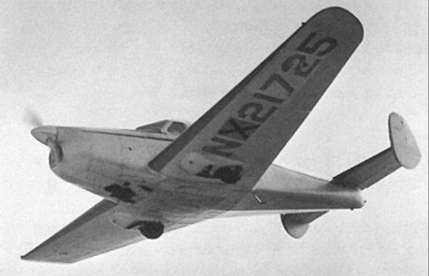
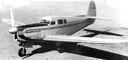
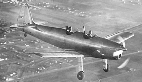
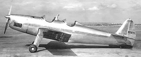
The Vega Starliner NX21725 was a five/six-seat low-wing cabin monoplane with retractable landing gear and an unusual powerplant. The model 22 was a modification with 640hp Menasco Unitwin 2-544 and a single tail. This comprised two 194kW Menasco C6S-4 inline engines, mounted side-by-side, and coupled to drive together, or independently in emergency, a single propeller.
First flown on 22 April 1939 (piloted by B A Martin), the Starliner was abandoned after some 85 flight test hours as there was no demand for an aircraft in this category.
Vega Starliner NX21725
The aircraft was sold to a film studio and its track faded.
Engines: two 194kW Menasco C6S-4 Unitwin Wingspan: 12.50 m / 41 ft 0 in Length: 31’6″ Max take-off weight: 2722 kg / 6001 lb Useful load: 1660 lb Max. speed: 338 km/h / 210 mph Cruise speed: 180 mph Stall: 60 mph Range: 600 mi Seats: 6
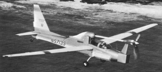
Potential of the QT-2 / Q-Star was such that Lockheed produced a refined version for the US Army: The YO-3A. Also based on the Schweizer SGS 2-32 Sail-Plane wings and tail unit, but with wings mounted low on the fuselage, retractable landing gear, upgraded (SLAE) avionics, State-Of-The-Art Sensor (NVAP with LTD) and the Tactical Observer seated forward for better visibility. A 156.5kW IO-360D Continental Engine provided propulsion power. The YO-3A was deployed in Southeast Asia from mid-1969 to late-1971.
It was the first military aircraft to employ an integrated NOD Sensor with a YAG Laser. It also had an Infrared Illuminator for other tactical sensors (INFANT LLTV, NODs, etc). The YO-3A was deployed in Vietnam for more than a year.
It was later operated by the Louisiana Dept of Wildlife & Fisheries (LDWF) and FBI. NASA operated the former 69-18010 as NASA 818 (or similar).
One YO-3A is preserved in the Army Aviation Museum at Fort Rucker, Alabama. YO-3A 69-18005 is on display at the Museum of Flight in Seattle, Washington. YO-3A 69-18006 is on display at the Pima Air and Space, Tucson AZ. YO-3A 69-18007 is in storage at the Western Museum of Flight in Torrance, California. As of 2014, YO-3A 69-18010 (NASA 818) is in flyable storage at Armstrong Flight Research Center.
YO 3A Engine: Continental, 210 hp. Wing span: 57 ft 0 in (17.40 m). Length: 30 ft (9.14 m). Gross weight: 2,167 lb (983 kg). Max speed: 149 mph (240 km/h). Crew: 2.
Faced with the military requirement for a quiet observation aircraft, Lockheed Missiles & Space Co. (LMSC) developed the “Q” Series Aircraft: QT-1 (conceived, but not constructed), QT-2 (N2471W and N2472W) later modified to QT-2PC configuration (#1 and #2), and Q-Star. Note: “QT: for Quiet Thruster.
The Q-Star Aircraft was LMSC’s “House Aircraft” for evaluating “quiet recon” concepts. Eighteen propeller/reduction systems and other items were evaluated. It flew early versions “Black Crow” Sensors and was the first aircraft to use a rotary combustion chamber (Wankel) engine for primary power.
Two Schweizer 2-32s (67-15345 and 67-15346) from the U.S. Naval Test Pilot School X-26 Program (USNTPS) were modified to QT-2 configuration (QT for Quiet Thruster) by the Lockheed Missiles & Space Co. (LMSC) and civil registered as N2471W and N2472W.
In 1967 the aircraft were modified by adding a Continental O-200 engine, V-Belt RPM reduction system, four-bladed fixed pitch wood (Fahlin) propeller, and airframe upgrades. The QT-2 first flew in August 1967.
After demonstrating quiet flight, the aircraft were again modified to military QT-2PC configuration, known only as Tail Numbers “1” and “2”, with GFE avionics and camouflage for night operation. They were successfully evaluated in Southeast Asia (Prize Crew OpEval) for covert (“stealth”) tactical airborne observation in the spring of 1968 (during Têt). Arriving in South Vietnam just before the 1968 TET Offensive, they accumulated approximately 600 hours flying exclusively tactical night missions during the first three-month deployment. They continued to operate in Vietnam during most of 1968 (Prize CrewII) and were then transferred to the Navy (NTPS Pax. R.) as X-26Bs in 1969. The QT-2PCs were the first military aircraft to use “Starlight Scopes”.
QT-2PC #1 in the Soc Trang, RVN Army Airfield Hangar in 1968
The two QT-2PCs were returned to USNTPS in 1969 and re-designated X-26Bs.
The #1 QT-2PC was re-designated “67-15345” and the #2 aircraft was used for spare parts.
The #1 ship is now at USAAM at Ft. Rucker, AL. The #2 ship QT-2PC N2472W was retro-verted to SGS 2-32 configuration and is operated by Mile High Gliders in CO.
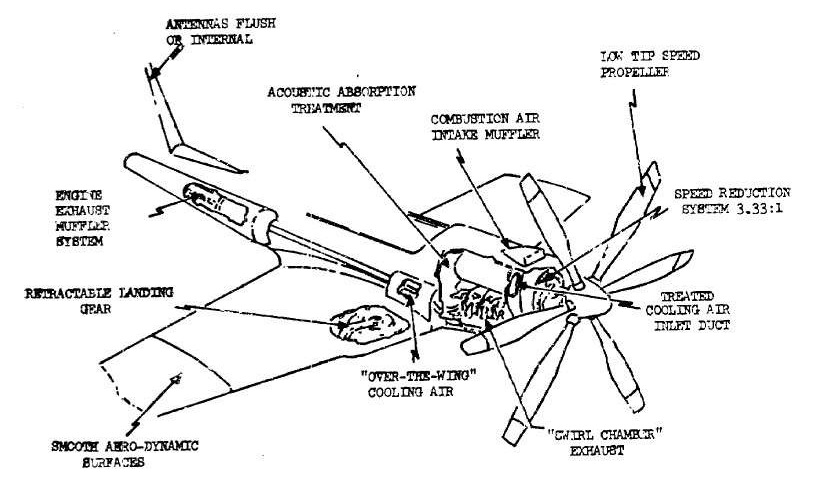
Lockheed Aircraft Corp. offered the rotating combustion engine its first chance to fly. Under a Navy contract, Lockheed was experimenting with ul¬tra quiet aircraft for undetected low altitude reconnaissance. Several air¬frame configurations, were developed culminating in the QT 3. Basically the QT 3 (QT for quiet thruster) consisted of a highly modified Schweizer 2 32 sailplane equipped with art amidship mounted Continental 100 horsepower engine turning a large slow turning propeller through a reduction drive and long overhead propeller shaft. The QT 3 yielded airframe and propellor noise so low that the most noticeable remaining sound was valve action in the engine. Endeavoring to eliminate valve noise, Lockheed’s engineers seized upon the RC engine since it has no valves, only ports.
Replacing the air cooled Continen¬tal with an RC 2 60 U5 liquid cooled engine required extensive reengineer¬ing. A Corvette aluminum radiator was grafted to the nose and redesigned reduction gearing was required. A 5.34/1, two stage ‘V’ belt reduction system reduced 6,000 rpm at the en¬gine down to 500 propeller rpm. Only 185 horsepower was used in the Q Star due to carburetor limitations. Nevertheless, power was increased by 85% with only a 6% increase in air¬frame weight. A three blade 90 100in constant speed propeller converted power to thrust. Laminated birch was used for blade material but at least one propeller had a balsa wood core covered with glass fibre.
Throughout the QT proj¬ect, Lockheed tested five 4 blade, two 6 blade, and two 3 blade props.
Flight testing revealed previously un¬attainable levels of quiet flight. Com¬pound muffling culminated in a discharge pipe pointing straight up. Re¬sidual noise was thereby directed away from the ground. As a test a Cessna 182 and the Q Star, both load¬ed to 2,600 pounds gross weight, were flown over the airport at 800 feet. The 182 was easily detectable by engine and propeller noise; Q Star was almost impossible to detect. Even at 400 feet the Q Star sounded only like leaves rustling in a light wind. In the cockpit, engine noise is similar to the hum of an electric motor and even then, most noise in the cockpit seemed to be aerodynamically originated.
Potential of the QT-2 / Q-Star was such that Lockheed produced a refined version for the US Army: The YO-3A.
Engine: 1 x Cont. IO-360, 154kW Wingspan: 17.4 m / 57 ft 1 in Length: 9.2 m / 30 ft 2 in Wing area: 17.0 sq.m / 182.99 sq ft Crew: 2
QT-2PC Engine: 1 × Continental O-200, 100 hp (75 kW) Propeller: Ole Fahlin four-blade, 8 inch chord, fixed-pitch 100 inch diameter Wingspan: 57 ft 1.5 in (17.37 m) Wing area: 185 ft² (16.7 m²) Wing aspect ratio: 18 Length: 30 ft 9 in (9.33 m) Height: 9 ft 3 in (2.74 m) Loaded weight: 2,500 lb (kg) Fuel Capacity: 20 gallons (nominal) Service ceiling: 13,000 ft (m) Rate of climb: 200 ft/min (m/s) Quiet cruise speed: 70 – 80 mph Wing loading: kg/m² (lb/ft²) Flight endurance: Planned = 4+ hours; demonstrated = 6.7+ hours Crew: two
North American Aviation Inc, designed during 1937 the prototype of a lightweight primary trainer which it designated North American NA-35. Powered by a 93kW Menasco Pirate inline engine, it was of low-wing monoplane configuration with fixed tail-wheel landing gear, and seated the instructor and pupil in tandem open cockpits. First flown in October 1940, piloted by B A “Bud” Martin.
Vega 35-67 NX14299
When the NA-35 failed to win a US Army Air Corps contract in 1939, North American sold all rights, along with prototype NX14299 and 4 unfinished planes, to Lockheed’s Vega subsidiary in October 1940.
Vega 35-67 NX14299
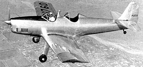
Vega built only four of these Vega 35 aircraft (ATC 741), NX21760, and NX28351-28353, two converted to 35-70 (ATC 741) with more powerful 119kW Menasco Pirate D-B engines, the first flown in 1941, but by then the company had no manufacturing capacity available and Vega 35 production was abandoned. The wing design was used as basis for prototype NAvion.
Vega 35-67 NX21760
The model 37 of 1941 was wartime production of Lockheed Vega.
35-67 Engine: 125hp Menasco D-4 Wingspan: 9.07 m / 29 ft 9 in Length: 25’6″ Useful load: 549 lb Max. speed: 124 mph Cruise speed: 108 mph Stall: 48 mph Range: 320 mi Seats: 2
35-70 Engine: 150hp Menasco C-4S Wingspan: 9.07 m / 29 ft 9 in Length: 25’6″ Useful load: 542 lb Max speed: 140 mph Cruise speed: 124 mph Stall: 46 mph Range: 305 mi Seats: 2
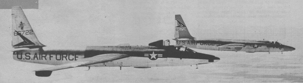
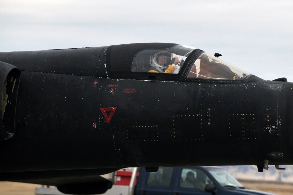
The U 2 was designed by Kelly Johnson to fly high and far. His equation stressed simplicity: flush rivets, high aspect ratio wet wing, ultralight structure, stunning power to weight ratio. Conceived originally to meet a CIA requirement for an aircraft with the potential of operating at extreme altitude and first flown in the mid-1950s, the U-2’s unique capabilities rendered it virtually immune from interception, and made possible repeated overflights of the Soviet Union, as part of the intelligence-gathering efforts of that era.
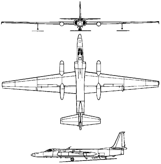
The requirement for high altitude and long range needed an aircraft with low wing loading, the latter large quantities of heavy fuel to confer the necessary range. Therefore the U-2 is of very lightweight construction, dispensing with conventional landing gear and pressurisation to save extra weight, and having wings of large area. Landing gear is of bicycle type with single wheels fore and aft, and balanced on the ground by wing-tip ‘pogos’ – a strut and wheel device which drops away when the U-2 becomes airborne – was selected. The pilot is accommodated on a light-weight seat, dressed in a semi-pressure suit with his head enclosed in an astronaut-type helmet, and forced to breathe pure oxygen for his survival. A medium-powered turbojet is adequate to lift this lightweight aircraft, and long range is possible by shutting it down and gliding for long periods.
Development of the U-2 began in the spring of 1954 to meet a joint CIA/USAF requirement for a high-altitude strategic reconnaissance and special-purpose research aircraft. It took place in the Lockheed ‘Skunk Works’ at Burbank, California, where – after acceptance of the design in late 1954 – two prototypes were hand-built in great secrecy by a small team of engineers. The aircraft’s true purpose was cloaked under the USAF U-for-Utility designation U-2, and the first flight took place on or about 1 August 1955. Once military power is on the engine for takeoff, the throttle was not touched again until ready for descent. Speed is kept fairly constant at Mach 0.715, and excess power was traded for cruise-climb altitude gain.
At about the same time US President Dwight D. Eisenhower was proposing his ‘Open Skies’ policy, one of mutual East/West aerial reconnaissance of territories. President Eisenhower hoped that his policy would reduce tension between East and West, thus preventing the growth of the nuclear arms race. Unfortunately the Soviet Union would have nothing to do with this proposal. Consequently ‘Kelly’ Johnson’s new ‘spy plane’ assumed greater importance. The prototypes were followed by production of about 48 single-seat U-2A and U-2B with differing power plant, and five two-seat U-2D. Some U-2B were converted later to U-2D standard.
By 1960 about 25 U-2s had operated from bases in Japan, Pakistan, Turkey and Europe since 1957 on flights around and over Russian-controlled territory.
An additional batch of 12 U-2R was ordered in 1967. A new version, known as the TR-1, entered production as a tactical-reconnaissance aircraft, equipped with a variety of electronic sensors.
Referred to as just U-2, there has been reference to a U-2B and U-2D, as well as single-seat and two-place versions. Early Lockheeds were powered by a single 11,000-1b thrust P&W J57, later models are reported to have the more powerful J75P-13. Forward landing gear is dual pneumatic type, approximately 20 in diameter, is non-steerable; rear gear is dual hard rubber of approximately 8″ diameter and steerable. A lightly stressed thin skin covers the U-2. Lockheed Martin’s Skunk Works has rewired the U-2s over the years during maintenance checks to make the aircraft compatible in the electro-magnetic interference environment.
The initial U-2As built by Lockheed in the 1950s either have been destroyed by accidents, combat or have been retired. They have been operating from Edwards AFB since 1957. The 40% larger U-2R was developed in the late 1960s, and deliveries to the Air Force started in 1969.
In addition to photo and electronic reconnaissance, U-2 were used for weather reconnaissance, high-altitude research, measurement of radiation levels, and for the tracking and recovery of space capsules. They were used for reconnaissance during the Cuban crisis, in Vietnam and during the Arab-Israeli conflict.
The destruction of the U-2B aircraft being flown by Francis ‘Gary’ Powers on 1 May 1960 brought an abrupt halt to this phase of activities, CIA attentions then focussing on the People’s Republic of China which in the early 1960s was fast emerging as a major nuclear power.
In August 1964 an Air Force U-2 crashed bear Boise, Idaho, the Chinese Nationalist Air Force officer pilot being trained at Davis-Monthan AFB 4080th Wing, parachuted to safety. This was the first indication that Chinese Nationalist pilots were being trained in the US. Three U-2s piloted by Chinese Nationalist pilots from Formosa bases had been shot down over Communist China, the first in September 1962. The US had reported selling only two U-2s the Formosa.
U-2 and TR-1 operations are usually conducted in what is best described as a ‘permissive’ environment on the friendly side of important frontiers.
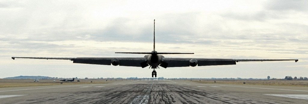
Powered by the Pratt & Whitney J75, the craft rotates in less than 200 feet as wheeled outriggers fall away. Climbing at 160 knots and 6,000 plus fpm initially, sustaining 45 degrees pitch up. Only to the 45,000 foot physiological limit in the two seat trainer version without pressure suits, but the U 2 will climb to 70,000 plus. Stressed for 1.7 positive Gs and half a G negative, the U 2 demands a gentle hand.
Scrupulous energy management alti¬tude, attitude, airspeed, power setting ¬measures successful landings. Each ex¬cess foot at the threshold puts you 1,000 foot farther to touchdown. Two point land¬ings are essential; touching front wheel first causes ballooning in ground effect.
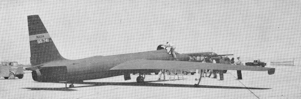
A couple of original production examples were assigned to NASA.
The Strategic Air Command use the U-2R which entered service in the late 1960s and which differs from its predecessors by virtue of greatly increased length and wing span. The U-2R was joined by an increasing number of TR-1s, these externally being very similar although they are intended for tactical rather than strategic missions. At least 25 of these were ordered by the USAF in 1968.
From 2002, Lockheed Martin upgraded the 31 strong U-2 fleet with state of the art glass cockpit displays and controls as the U-2S.
The service bought 37 TR-1 s in the 1980s, with the last one delivered in 1989, and these were the core of the U-2S and U-2STs in operation by the 9th Reconnaissance Wing here. The replacement of the Pratt & Whitney J75 turbine engine by the General Electric F101-GE-F29 turbofan in the 1990s caused the redesignation of the U-2R to the U-2S. The GE engine was later redesignated the F 118-GE-101.
The F 118 fuel consumption is some 16% less than the J75, which allows for a 1,220-naut.-mi. increase in range, or increased time on station. The 1,300-1b. lower weight of the General Electric engine also allows a 3,500-ft. increase in operational altitude and an increased payload. The U-2’s primary defense against both aircraft and surface-to-air missiles is its altitude, although newer variants of air-to-air and surface-to-air missiles can reach the U-2’s altitude. The reconnaissance aircraft is equipped with a radar warning system, but not with active defenses, such as flares or chaff.
The Air Force will still only say that the U-2 will fly above 70,000 ft., but the actual normal operational altitude is below 80,000 ft. and above 75,000 ft.
For descent almost everything possible on the aircraft is extended. The throttle to idle, lowered landing gear, raised spoilers and flaps in the gust-up configuration and extended fuselage-mounted speed brakes. Once stable on descent, the rate is dose to 3,000 fpm. A speed of Mach 0.715 is used to 53,000 ft., when a speed of 160 kt. is established. In the case of either an engine or electrical failure, with the aircraft descending clean, it could easily take longer than an hour to descend from altitude. The battery in the U-2S has a life of about 1 hr. and would run out just about when you needed to talk with the tower about deadstick landing instructions. The pilot also is able to raise the spoilers for landing with a micropump and accumulators, a new feature to the U-2.
Pilots claim that the U-2 is one of the hardest aircraft to land because of the need to stall the aircraft on landing and touch down rear wheel first, not to mention the effect of wind on the glider-like aircraft.
TR-1A
The U-2 aircraft was ordered back into production in 1979 as a high altitude tactical reconnais¬sance platform, this time as the TR-1A. The TR-1A is designed for tactical reconnaissance primarily in the European theatre, using UPD-X side-looking airborne radar (Slar) for surveillance up to 55km into hostile territory from friendly areas.
The first TR-1A flew on 1 August 1981 and the USAF acquired 26 of these single seaters plus two two-seat TR-1Bs. In 1984 the TR-1A flew with the precision location/strike system (PLSS) and, following successful trials, at least some of the fleet were to be allocated to this role. PLSS involves the use of three TR-lAs to detect and locate emitters and then direct attacks upon them.
In 1982 the USAF began taking delivery. Using the same basic airframe as the U-2R, the TR-1A high altitude battlefield reconnaissance aircraft was operational with the USAF flying from bases in Europe including the UK in 1990. It is equipped with an advanced sideways looking airborne radar (SLAR) and incorporates the latest ECM.
Two examples of a two-seat variant known as the TR-1B were assigned to training duties at Beale AFB, California. The TR-1B trainer has a second, raised cockpit in tandem.
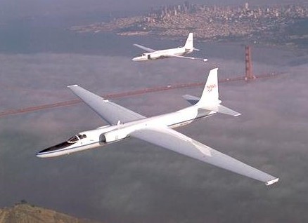
ER-2
Replacing earlier U 2C’s, NASA took delivery of three ER-¬2’s, (the NASA designation for the TR 1A). The three are 80¬1063 / N706NA, 80 1069 / N708NA and 80 1097 / N709A. The first was delivered in June 1981 and the last (80 1097) was delivered in April 1989. Two are owned by NASA, while the third is leased from the USAF.
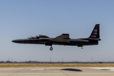
A Lockheed U-2S Dragon Lady, assigned to the 9th Reconnaissance Wing (RW) at Beale Air Force Base (AFB), California, successfully completed a test flight equipped with an AI algorithm under the control of USAF pilot, Maj “Vudu” on December 15, 2020. The first US military aircraft to fly with an artificial intelligence (AI) co-pilot.
Maj “Vudu” USAF U-2S Dragon Lady pilot assigned to the 9th RW on December 15, 2020.
The U-2S, developed by Air Combat Command’s U-2 Federal Laboratory, the algorithm – known as ARTUμ – was named in reference to the fan-favourite droid, R2-D2, from the Star Wars franchise. The system is designed to completed specific in-flight tasks that would otherwise have been completed by the pilot.
During the test flight, ARTUμ took control of the U-2’s sensors and tactical navigation systems, leaving Maj “Vudu” to fly the aircraft and coordinate with the AI on sensor operation. The Dragon Lady flew a reconnaissance mission during a simulated missile strike, in which ARTUμ was responsible for locating enemy launchers, while the pilot looked out for threatening aircraft. Both the human pilot and AI co-pilot shared the U-2’s radar throughout the test sortie.
The USAF adds that the test flight “was part of a precisely constructed scenario, which pitted the AI against another dynamic computer algorithm in order to prove the new technology.” It explained that control of the U-2’s sensors was handed over to ARTUμ after take-off, which then used insight gained from more than half-a-million computer simulated training missions to manipulate the sensors in-flight. Maj “Vudu” and ARTUμ successfully teamed-up during the demonstration to share the Dragon Lady’s sensors and all mission objectives were achieved, the service concluded.
A Lockheed U-2S Dragon Lady high-altitude reconnaissance aircraft, 9th Reconnaissance Wing (RW), Beale AFB, California, on December 15, 2020.
A two-seat TU-2S trainer variant of the U-2 logged a more than 14h flight covering over 6,000nm (11,110km) while overflying the 48 contiguous states of the continental USA setting a new endurance record for the type. The US Air Force (USAF) confirmed the flight on 1 August, noting the long-distance sortie launched from the U-2 fleet’s home base at Beale AFB in California’s Sacramento Valley on 31 July 2025. The success of the long-endurance mission pushed the U-2S “beyond its known limits”, the air force says. “The flight itself maxed out the operational range of the U-2 and placed the pilots at the edge of their physiological limit,” the service notes.
TU-2S
The timing of the record-setting sortie was likely deliberate. The USAF is seeking to retire is fleet of 24 operational U-2S and three TU-2S jets by 2026, while advocates for the Cold War-era platform look for arguments to keep the type flying.
U-2A Engine: 1 x Pratt & Whitney J57 P 37A turbojet, 11,200 lb (5,080 kg) st. Wing span: 80 ft 0 in (24.38 m). Length: 49 ft 7 in (15.11 m). Height: 13 ft 0 in (3.96 m). Gross weight: 15,850 lb (7,190 kg). Max speed: 495 mph (797 km/h) at 40,000 ft (12,200 m). Crew: 1. Armament: None. Typical range: 2,200 miles (3,540 km).
U-2B Engine: 1 x Pratt & Whitney J75. Seats: 1.
U-2C Engine: 1 x Pratt-Whitney J75-P-13B, 7711kg Max take-off weight: 10225 kg / 22542 lb Wingspan: 24.38 m / 80 ft 2 in Length: 15.24 m / 49 ft 8 in Height: 4.57 m / 14 ft 12 in Wing area: 52.49 sq.m / 565.00 sq ft Cruise speed: 740 km/h / 460 mph Op speed: Mach .73 to .80 Ceiling: 27000 m / 88600 ft Range: 4635 km / 2880 miles at 475-mph at 70,000-ft Flight endurance: 7.5 hr Crew: 1 Rate of climb: 8,000 fpm at 160-kt Time to 30,000 ft: 5 min Time to 50,000 ft: 9 min Time to 60,000 ft: 12.5 min Cruise climb to 70,000 ft: 28 min Indicated airspeed (IAS) above 70,000 ft:110 kt Mach buffet speed: 115 kt IAS / 410 kt TAS
U-2D Engine: 1 x Pratt & Whitney J75. Seats: 2.
U-2R Range: 3,000-plus miles (2,609 nautical miles).
U-2S
TR-1A Engine: 1 x Pratt & Whitney J75-PW-13B turbojet, 7711 kg (17,000-lb) thrust Estimated maximum cruise speed at over 21335 m (70,000 ft) 692 km/h (430 mph) (Mach 0.57) Operational ceiling est: 27430 m (90,000 ft) Maximum range: 4825+ km (3,000+ miles). Fuel internal: 4450 lt. Endurance: 12 hr. Air refuel: No. Seats: 1. Empty weight: about 7258 kg (16,000 lb) Maximum take-off 18144 kg (40,000 lb). Wing span 31.39 m (103 ft 0 in) Length 19.20 m (63 ft 0 in) Height 4.88 m (16 ft 0 in) Wing area about 92.90 sq.m (1,000 sq ft).
TR-1B Seats: 2.
ER-2 Engine: 1. Wing span: 105 ft. Op alt: 68,000 ft. Endurance: 8 hr.