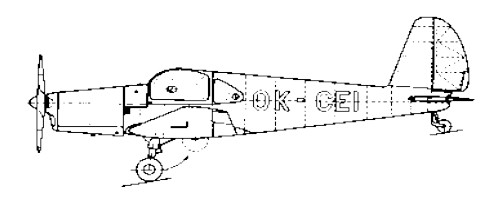
Produced by the former J,Meaz works (Chocen plant) the M-3 Bonzo was designed by J. Mraz.
The M-3 Bonzo is a four-seat produced in prototype form only. Of all-wood construction, it is powered by a 160 hp Walter Minor 6-III engine. A retractable nosewheel undercarriage is fitted.
Engine: 160 hp Walter Minor 6-III Wingspan: 34 ft 9 in Wing area: 148.5 sq.ft Length: 25 ft 4 in Height: 7 ft 4.5 in Empty weight: 1278 lb Loaded weight: 2424 lb Max speed: 165 mph Cruise: 150 mph ROC: 708 fpm Ceiling: 16,400 ft Range: 620 mi
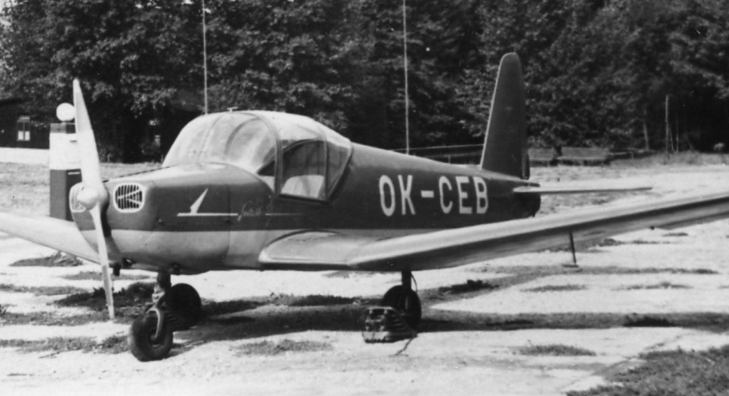
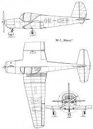
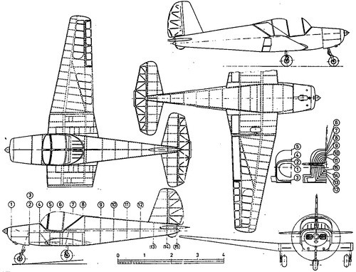
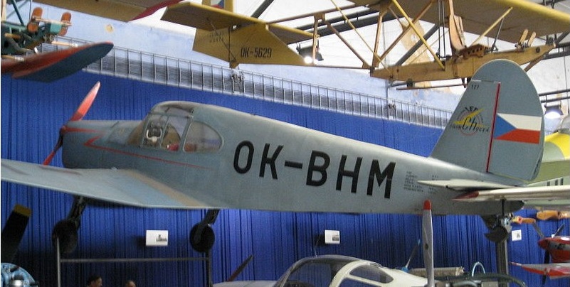
The Czechoslovak aircraft factory Mráz introduced several new sport aircraft after World War II. One of them was the M-2 Skaut, designed by Zdeněk Rublič. His aim was to design an easily flyable and reliable aircraft for basic club pilot training, with moderate operating costs and requiring little maintenance.
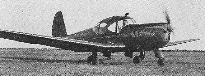
The Mráz M-2 Skaut was a wooden two-seat, single engine, low wing aircraft.
To simplify production, the wing and tail from his earlier, successful M-1C Sokol design was used. Like the Sokol, the Skaut was a wood framed, fabric covered aircraft. Their shared straight tapered wing had a swept leading edge but no sweep on the trailing edge They had marked dihedral beyond a very short centre section. The fin also had a swept leading edge and carried a rounded rudder. The tailplane was set well to the rear and near the top of the fuselage with a single piece elevator; the rudder moved above it. The Skaut had fixed tricycle landing gear.
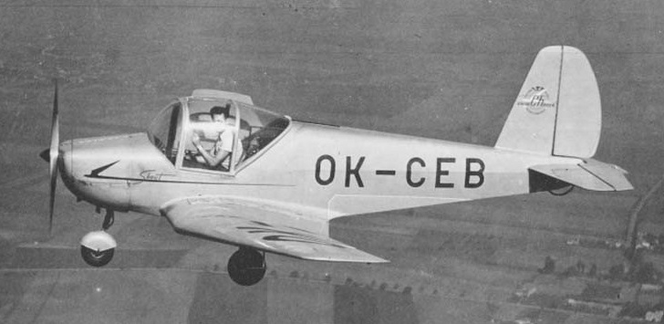
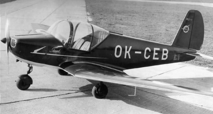
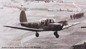
The prototype, first flown in mid-1948, showed that the Skaut was a stable and safe aircraft, pleasantly controllable and with a good field of view. These characteristics together with a side-by-side cockpit and a tricycle landing gear made it a promising civil trainer aircraft. However, the new communist government nationalised the Mráz factory and directed it to produce military aircraft, so only the prototype Skaut was completed in the 20th century.
The only wooden prototype Skaut, OK-CEB Svazák, served at several flying clubs, mostly in Vrchlabí, and became very popular. There are rumours that it was flown solo by glider pilots without any previous experience of powered aircraft. In the early 1960s it was damaged during an emergency landing after an engine failure and was scrapped.
In 2005 the design was revisited, resulting in the metal framed, modernised Kubicek M-2 Scout which first flew in 2009 with plans for production and first deliveries in 2011.
Variation: Kubicek M-2 Scout
Powerplant: 1 × Praga D, 56 kW (75 hp) Propeller: 2-bladed fixed pitch Wingspan: 10 m (32 ft 10 in) Wing area: 13.8 m2 (149 sq ft) Length: 6.75 m (22 ft 2 in) Height: 1.9 m (6 ft 3 in) Empty weight: 370 kg (816 lb) Gross weight: 660 kg (1,455 lb) Fuel capacity: 70 L (18 US gal; 15 imp gal) Maximum speed: 185 km/h (115 mph, 100 kn) Cruise speed: 150 km/h (93 mph, 81 kn) Range: 700 km (430 mi, 380 nmi) Service ceiling: 4,200 m (13,800 ft) Rate of climb: 2.7 m/s (530 ft/min) Crew: 2
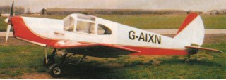
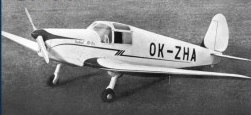
The Mráz M.1 Sokol (English: “Falcon”) was a light aircraft built in Czechoslovakia in the years following the end of the Second World War. Designed in secret by Zdeněk Rublič at the Beneš-Mráz factory during the German occupation.
The Sokol was a conventional, low-wing monoplane that took the pre-war Beneš-Mráz Bibi as its starting point. Two seats were provided side-by-side in an enclosed cabin, and the main units of the tailwheel undercarriage were retractable. Construction throughout was of wood.
M.1/1 prototype
The prototype, then designated the M.1/1 and registered as OK-ZHA, first flew on 9 March 1946, following test flights the prototype was designated the M.1A as the two-seat-version. A re-engined two-seater was built designated the M.1B with a ZLAS Toma 4 engine, it first flew on 19 May 1946 but only one was built. The design was then modified as the M.1C with a third-seat in the rear and first flying on 16 February 1947. The M.1C became the main production variant and 183 aircraft were built.
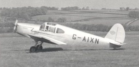
M1C Sokol G-AIXN at Leeds (Yeadon) in 1954, and was still airworthy in 2019
In 1948 the M.1C was further developed as the M.1D with an enlarged single-piece canopy and a revised rudder. The M.1D first flew on 4 October 1948 and 104 were built. One M.1D was fitted with locally produced floats and re-designated the M.1E, it first flew in September 1949. A minor variant was the Para-Sokol which was fitted with rearward sliding canopy to allow parachutists to leave the aircraft.
Some were operated by the Czechoslovakian National Security Guard and Egyptian Air Force.
Around 284 aircraft were built but the wooden-glued airframes were condemned in the early 1960s and withdrawn from use, under 20 were still in existence in the 2010s but only a few were flyable.
G-AIXN landing at its home base of Turweston Aerodrome in the United Kingdom in 2017
Some are on display at Museums in the Czech Republic, Hungary, Beijing, China, and Datangshan, China.
M-1A Original two-seat version Engine: Walter Minor
M-1B Similar to M-1A Engine: ZLAS Toma 1 built
M-1C Revised version, with longer fuselage and third seat, and swept leading edges on wing 183 built
M-1D Similar to M-1C with new, single-piece canopy and larger rear windows Engine: 1 × Walter Minor 4-III, 78 kW (105 hp) Wingspan: 10.0 m (32 ft 10 in) Length: 7.35 m (24 ft 1 in) Wing area: 13.8 m2 (149 sq ft) Height: 2.20 m (7 ft 3 in) (tail up) Empty weight: 425 kg (937 lb) Gross weight: 780 kg (1,720 lb) Maximum speed: 240 km/h (150 mph, 130 kn) Cruise speed: 212 km/h (132 mph, 114 kn) Range: 1,000 km (620 mi, 540 nmi) Service ceiling: 4,800 m (15,700 ft) Rate of climb: 3.0 m/s (590 ft/min) Crew: 1 Capacity: 2 passengers 104 built
M-1E Similar to M-1D but equipped with pontoons at least 1 built
The Jupiter was an executive transport designed by André Moynet, a member of the National Assembly of France and a former government minister and built by S.S. Engins Matra (so it is sometimes referred to as the Matra Moynet Jupiter).
The Jupiter design began life in 1957 as a single-engine airplane, but evolved into its unusual “push-pull” arrangement during the design process. Moynet adopted the configuration to provide the power and safety of a twin, but without asymmetric handling characteristics.
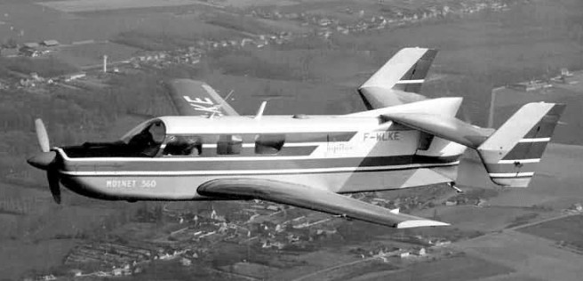
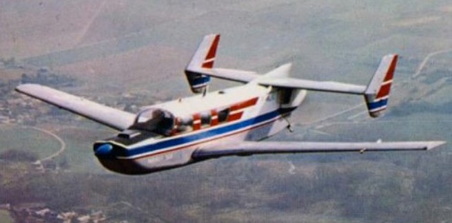
The Moynet 360 Jupiter was an example of a push-pull aircraft with a single conventional fuselage and an engine at either end. Its wing had a straight trailing edge, but the centre section had strong taper on the leading edge which continued more weakly outboard. It was of two spar, stressed skin construction, carrying mass balanced ailerons and slotted flaps. The main undercarriage legs, placed at the end of the centre section each carried a single wheel and retracted inwards electrically. A retractable nosewheel completed the landing gear.
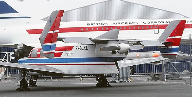
One horizontally opposed Lycoming engine was conventionally placed in the nose. Behind it was a standard cabin, though the front seats were further ahead of the leading edge than usual because of the rearward shift of the centre of gravity caused by the rear engine. There were three large windows on each side. For the same reason the rear fuselage was quite short, and it lacked the normal taper, giving it a boxy look, so that the second, pusher Lycoming could be mounted in the extreme tail. This was cooled by air from rectangular intakes on the upper sides of the rear fuselage. The straight edged, tapered tailplane was mounted on the fuselage top above the engine, with small endplate fins carrying balanced rudders. These fins extended above and below the tailplane, with arrow shaped leading edges and straight, swept trailing edges. There was also a long, shallow strake over the rear fuselage. Seen from below, the long span of the tailplane was striking, about 44% of that of the wings; the elevators filled most of the outer part of its trailing edge, avoiding the propeller airstream.
Moynet had the support of Marcel Chassigny, then the head of the Matra company, and between them they hoped that the Jupiter 360 could provide real competition to U.S.-designed light aircraft. Matra’s Lucien Tieles partnered with Moynet on the final design. The first prototype flying on 17 December 1963 at Villacoublay with the designer and Lucien Tieles at the controls.
Only two Jupiters were built (plus a single static test airframe). The first, constructed by Matra, designated 360-4 and initially registered as F-WLKE had two 200 hp (150 kW) Lycoming IO-360-A1A engines driving two-bladed propellers and was configured as a 4-5 seater.
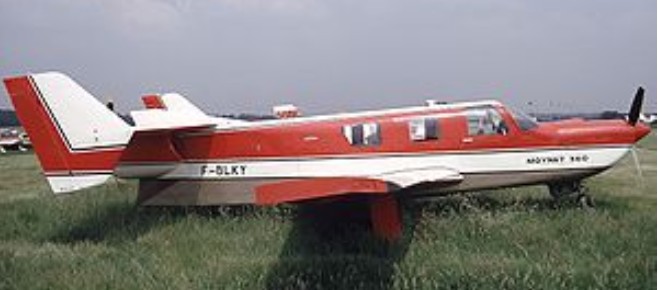
The second prototype, second constructed by Sud-Aviation, was of a more powerful and slightly larger variant designated the model 360-6; it first flew on 25 May 1965. This model had a choice of engines, either 290 hp (216 kW) Lycoming IO-540 six cylinder engines driving constant speed, three-bladed propellers, or 310 hp (231 kW) Lycoming TIO-541 engines. The span was increased by 0.37 m (15 in) and length by 0.64 m (25 in). The increased length allowed seats for 6-7, with two rows of two single seats and a bench seat at the rear that could accommodate 2 or 3. The cabin was sound-proofed and air conditioned and could be pressurised. Access was via a forward starboard side door. There was baggage space behind the cabin with its own external door. The sole 360-6 was registered as F-WLKY.
The intention was for Sud-Aviation to produce the 360-6 Jupiter as the Sud-Aviation M 360-6 Jupiter, but no sales resulted. An order was obtained from the French government for some 360-6 pre-production aircraft, but this seems to have been cancelled. Despite sales campaigns in Europe and the U.S.A. no further orders resulted.
The first prototype is now in the reserve collection of the Musée de l’Air et de l’Espace, Le Bourget Airport, Paris museum. Parts of its fuselage were to be used as the gondola of an abortive airship project, before it was recovered by Ailes Anciennes Le Bourget and presented to the museum. At le Bourget, the 360-4 bears the normal French registration F-BLKE rather than the French prototype style F-WLKE.
Moynet 360-4 “Jupiter” n°01
Moynet himself retained the second aircraft, the six-seater 360-6 F-BLKY. It passed into the hands of the Musée Régional de l’Air Angers – Loire Airport, France, after Moynet’s death in 1993. Limited restoration work was carried out in 1994 and from 1998, before the major current restore-to-flight effort began in 2009, undertaken by six volunteers. In March 2012 the museum signed a partnership agreement with the Association Aérospatiale Matra to aid with the restoration.
M 360-4 Jupiter First prototype, 4–5 seats, two 149 kW (200 hp) Lycoming IO-360 engines.
M 360-6 Second prototype, with stretched fuselage with seven seats and two 216 kW (290 hp) Lycoming IO-540 engines.
M 360-6P Proposed pressurised seven-seat version, with Lycoming O-480 engines. Unbuilt.
Sud-Aviation Présidence Further enlarged, pressurised version planned by Sud-Aviation.
Specifications:
M 360-4 Jupiter Engines: two 149 kW (200 hp) Lycoming IO-360 Wingspan: 35.42 ft Length: 25.81 ft Seats: 4–5
360-6 Engines: 2 x Lycoming IO-540, 216 kW (290 hp) Propellers: 3-bladed Hartzell constant speed Length: 8.77 m (28 ft 9 in) Wingspan: 11.49 m (37 ft 8 in) Height: 2.46 m (8 ft 1 in) Wing area: 16.81 sq.m (180.9 sq ft) Empty weight: 1,338 kg (2,950 lb) Gross weight: 2,390 kg (5,269 lb) Fuel capacity: 566 lt Maximum speed: 363 km/h (226 mph; 196 kn) at sea level Cruising speed: 338 km/h (210 mph; 183 kn) at 1,830 m (6,000 ft) on 75% power Range: 2,060 km (1,280 mi; 1,112 nmi) at 4,500 m(15,000 ft) and 45% power. Rate of climb: 7.3 m/s (1,440 ft/min) at sea level Capacity: 6 or 7
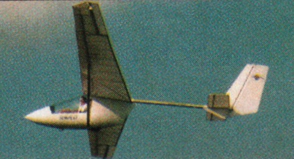
Designed by Bobby Bailey, the Tempest is an FAI Class 4 light sailplane circa 1998, using tube and fabric construction, and composite cockpit. It can be dismantled into three parts for transport. The semi-enclosed fiberglass cockpit has a canopy that hinges to one side.
Launchable by towing from an UL, it was availablein the US as a kit for $10,000 or as a completed sailplane for $12,500, through Quest Air Soaring Canter, 6548 Groveland Airport Road, Groveland, Florida 34736.
Tempest Wing span: 13 m / 42 feet Wing area: 14 sq.m / 150 square feet Height: 5 ft Length: 21 ft Aspect ratio: 12:1 MTOW: 400 lb Empty weight: 100 kg / 220 lb Vzmin: 0.8 ẚ 40 m/sec Stalls: 29 km/h Speed max: 80 mph Glide Ratio: 25 @ 60 kph L/D: 24 @ 68 km/h L/D ratio: 5:1 Min sink: 170 fpm Seats: 1 Landing gear: single wheel Price (1998) $ 10500 (kit)
The main product from the LiteFlite stable is the Dragonfly. The Dragonfly is a three axis ultra light aircraft which takes off in a reasonably small area and lands in a reasonably small area. It has dual seating and dual controls.
Due to the slow flying speed, the Dragonfly is a favoured hang gliding towing aircraft and has been sold to 12 different countries. The Dragonfly provides a low cost form of aviation which can be flown almost anywhere and is really easy to learn.
The Dragonfly has been in production since 1990 and during this period, in excess of 100 aircraft have been manufactured.
The Dragonfly is constructed from 6061 grade aluminium tubing, is structurally supported by stainless steel wire and has fabric covered wings. It is powered by either a two stroke or four stroke engine. It has a range of options available depending upon your requirements and financial constraints.
Engine: Rotax 582, 65 hp Overall Length: 5.974 m / 19 ft 6 in Maximum Height: 2.316 m / 7 ft 6 in Wing Span: 10.363 m / 34 ft Wing Area: 15.8 sq.m / 170 sq.ft MTOW: 385 kg Gross Weight: 800 lb Empty Weight: 150 kg / 330 lb Fuel cap: 6 USG / 20 lt VNE: 57 knots / 100 kph VC at 5200rpm: 40 knots / 60 kph Stall: 14-17 kt Normal Landing Approach Speed: 26 kt ROC: 1400 fpm /16 m/s Take-off dist: 50 ft Take-Off Distance (To 50ft): 195 feet Landing dist: 100 ft Landing Distance (From 50ft): 363 feet Range: 100 sm Fuel consumption: 16 lt/hr Service ceiling: 16,000 ft Seats: 2 Kit price (1998): US$15,700 Landing gear: tail wheel
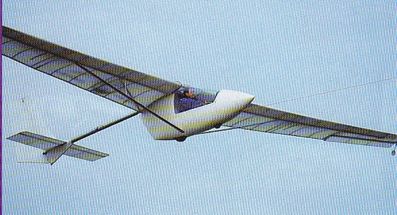
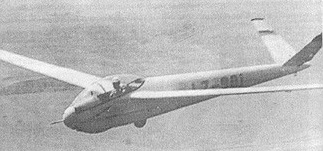
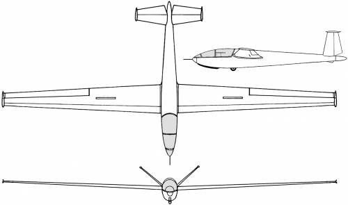
The second postwar Bulgarian sailplane designed by Eng L. Panov and D. Panchovsky, the Kometa-Standard (or Comet Standard) fully aerobatic Standard Class single-seater flew for the first time in prototype form on 5 August 1960; the type later went into small-scale production for the Bulgarian gliding clubs.
The Kometa-Standard is a cantilever midwing monoplane of conventional wooden construction with a butterfly-type V-tail with an included angle between the tailplanes of 110°. The wings, straight tapered in plan and set at mid-wing position, are single-spar wooden structures with a leading edge plywood torsion box and wing tip ‘salmon’-type fairings; the slotted ailerons are fabric-covered and there are spoilers on the wing upper and lower surfaces. They had 4° of dihedral. The Kometa-Standard had mass-balanced, slotted ailerons and spoilers at 60% chord which opened above and below the wing.
The plywood monocoque fuselage has a metal nose-cap and the landing gear consists of a non-retractable wheel with brake and a rubber mounted skid under the forward fuselage. The tail unit is of wooden construction with plywood and fabric covering, and the pilot is seated under a hinged Perspex canopy, proud of the rear fuselage line, but this was lowered and reshaped on the production Kometa-Standard II, merging into the rear fuselage from which it was hinged.
Kometa – Standard II
The cockpit was changed again in the Kometa-Standard III which had a sliding canopy over a reclining seat, making this variant 30 km/h (19 mph) faster than the Kometa-Standard II. Overall, the fuselage tapered uniformly from the cockpit to the tail. The Kometa-Standard had a 110° butterfly tail, its plywood and fabric covered surfaces terminating, like the wings, in little salmon fairings. Its undercarriage was a fixed monowheel, fitted with a brake and assisted by a forward, rubber sprung skid.
The prototype was flown for the first time on 5 August 1960 and an initial batch of 10 Kometa-Standard IIs was built, followed by two batches, each of 10, of Kometa-Standard IIIs. Flown by Bulgarian clubs, they were fully aerobatic, though not cleared for cloud flying.
Kometa-Standard II Production variant with lowered, rear hinged canopy. 10 built.
Kometa-Standard III Further revision to nose/canopy lines with reclining seat and sliding canopy. 20 built.
Specifications:
Kometa-Standard Year: 1960 Span: 49 ft 0.5 in / 14.95 m Length: 22 ft 9.5 in / 6.95 m Wing area: 136.7 sq.ft / 12.90 sq. m Aspect ratio: 17.6 Empty weight: 573 lb / 240 kg Max weight: 750 lb / 340 kg Max speed: 130 mph (in smooth air) Max aero-tow speed: 93 mph Min sinking speed: 2.69 ft/sec at 48.5 mph Best glide ratio: 28:1 at 51 mph
Kometa-Standard II Length: 6.95 m (22 ft 10 in) Wingspan: 14.95 m (49 ft 1 in) Wing area: 12.70 m2 (136.7 sq ft) Aspect ratio: 17.6 Airfoil: NACA 43012A Empty weight: 240 kg (529 lb) Gross weight: 340 kg (750 lb) Never exceed speed: 210 km/h (130 mph; 113 kn) Rough air speed max: 150 km/h (93.2 mph; 81.0 kn) Aerotow speed: 150 km/h (93.2 mph; 81.0 kn) Winch launch speed: 100 km/h (62.1 mph; 54.0 kn) Terminal velocity: with full airbrakes 220 km/h (137 mph; 119 kn) g limits: +6.25 -3.3 at 220 km/h (136.7 mph; 118.8 kn) Maximum glide ratio: 28:1 at 82 km/h (51.0 mph; 44.3 kn) Rate of sink: 0.78 m/s (154 ft/min) at 78 km/h (48.5 mph; 42.1 kn) Wing loading: 26.70 kg/m2 (5.47 lb/sq ft) Crew: One
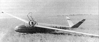
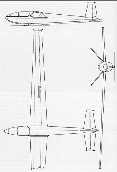
The Jastreb (or Hawk) two-seater fully aerobatic trainer was, with the Kometa-Standard single seater, one of the two indigenous Bulgarian designs that went into production in that country after the war.
The Jastreb was designed by Eng L.Panov and D. Panchovsky, the prototype making its first fight on 6 February 1948; the type was put into small-scale production for the Bulgarian clubs.
Of conventional wood and fabric construction, the Jastreb is a braced high wing monoplane with the centre section swept forward 5° at the quarter-chord line to improve the view from the rear seat, the absence of sweep on the outer panels enabling the spar to be uncranked. The wing is a single-spar wooden structure with leading edge plywood torsion box and is 30% fabric-covered; the wooden ailerons are plywood and fabric covered and there are spoilers in the wing upper and lower surfaces. The plywood-covered wooden fuselage has a metal nose-cap and the two pilots are seated in tandem under a sideways-opening Perspex canopy. The cantilever wooden tail unit is covered with plywood and fabric, and the landing gear consists of a fixed unsprung monowheel with no brake and a rubber mounted skid under the forward fuselage.
Span: 49 ft 2.5 in Length: 26 ft 3 in Wing area: 209.9 sq ft Aspect ratio: 11.55 Empty weight: 529 lb Max weight: 850 lb Max speed: 124 mph (in smooth air) Max aero-tow speed: 75 mph Min sinking speed: 2.95 ft/sec at 37 mph Best glide ratio: 20.5:1 mph
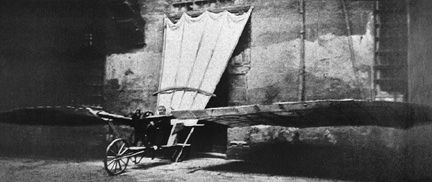
In 1881, Louis Mouillard wrote L’Empire de l’Air (Empire of the Air), in which he proposed fixed-wing gliders with cambered bird-like wings. He had been experimenting with gliders since 1856, and although his own gliders were unsuccessful, he realized the importance of gliding to the future of aviation – a perspective that was later shared by Otto Lilienthal. Photographed in Cairo, Egypt.
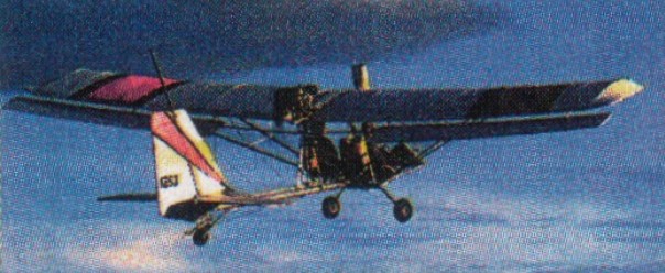
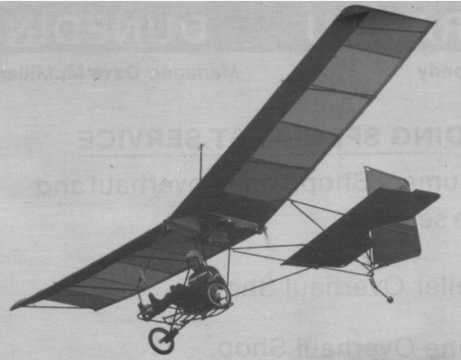
The Teratorn was a single seat single engined high wing monoplane with hybrid control. Wing has unswept leading and trailing edges, and constant chord; cruciform tail. Pitch control by weightshift; yaw control by fully flying rudder; roll control by one third span spollerons; control inputs through weight shift for pitch/yaw/roll. Wing braced from above by kingpost and cables, from below by cables; wing profile; 33% double surface. Undercarriage has three wheels in tail dragger formation; suspension on tailwheel and bungee suspension on main wheels. No ground steering. No brakes. Aluminium tube framework, without pod. Engine mounted above wing driving pusher propeller. Leading edges stiffened with Mylar.
The Teratorn which we are concerned with is itself a venerable design, having appeared at the birth of microlight aviation around the same time as the first powered version of the famous Quicksilver, with which it has a certain similarity. The Teratorn was powered, up till 1982, by the single cylinder Yamaha KT100S giving 15 hp through a reduction drive of 5/1, with initially the option and later the standard replacement by a twin cylinder Rotax of 28 hp with a 2.5/1 reduction drive.
On an original note, the company chose black anodising for the tubes on this hybrid control machine and the wires too were covered in black vinyl. The Teratorn is delivered as a kit requiring 20 to 25 h assembly according to the maker, and costs $3895 with the Rotax motor in 1983. Options include an instrument panel, skis, Kevlar floats and the choice of the Yamaha KT100S, which drops the price by $400. The machine is trailer transportable or on a roof rack and folds to around 16 x 5 x 1 ft (4.9 x 1.5 x 0.3 m). A kit allowing the Teratorn to be converted to the Teratorn TA with three axis control is also available.
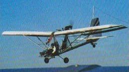
The Teratorn TA was a single seat single engined high wing mono¬plane with conventional three axis control. Wing has unswept leading and trailing edges, and constant chord; cruciform tall. Pitch control by elevator on tail; yaw control by fully flying rudder; roll control by one third span spoilerons; control inputs through stick for pitch/roll and pedals for yaw. Wing braced from above by kingpost and cables, from below by cables; wing profile; 33% double surface. Undercarriage has three wheels in tail dragger formation; steel spring suspension on tailwheel and bungee suspension on main wheels. No ground steering. No brakes. Aluminium tube framework, without pod. Engine mounted below wing driving pusher propeller.
This is the three axis version of the hybrid control Teratorn. The TA appeared in 1982 with the Yamaha KT100S 15 hp engine, though today that has become just an option, the machine being fitted in standard form with the Rotax 300 of 28 hp or the Rotax 377 with 34 hp. Rigging time for the earlier model is 25 min, while this model requires 25 min to rig with two people. The Teratorn TA is sold so that it requires only 20h to complete, according to the maker, and for a price of $4295 with Rotax 300 or $4595 with Rotax 377. The options include the Yamaha engine for a reduction of $300, floats of Kevlar, skis and instrument panel. Production was phased out in favour of the more advanced Tierra.
Teratorn Engine: Rotax 300, 28hp at 6200rpm Propeller diameter and pitch 60 x 24 inch, 1.52 x 0.61 m Reduction ratio 2.5/1 Power per unit area 0.18 hp/sq.ft, 1.9 hp/sq.m Fuel capacity 3.3 US gal, 2.8 Imp gal, 12.5 litre Length overall 18.0 ft, 5.49 m Height overall 9.0 ft, 2.74m Wing span 32.0ft, 9.75m Constant chord 5.0 ft, 1.52 m Sweepback 0 deg Total wing area 160 sq.ft, 14.9 sq.m Wing aspect ratio 6.4/1 Tailwheel diameter overall 3 inch, 7 cm Main wheels diameter overall 16 inch, 41 cm Empty weight 212 lb, 96 kg Max take off weight 474 lb, 215kg Payload 262 lb, 119kg Max wing loading 2.96 lb/sq.ft, 14.4 kg/sq.m Max power loading 16.9 lb/hp, 7.7kg/hp Load factors; +3.0, 3.0 ultimate Max level speed 50 mph, 80 kph Never exceed speed 55 mph, 88 kph Economic cruising speed 35 mph, 56 kph Stalling speed 15 mph, 24 kph Max climb rate at sea level 600 ft/min, 3.1 m/s Min sink rate 250 ft/min at 25 mph, 1.3 m/s at 40 kph Best glide ratio with power off 8/1 at 25 mph, 40 kph Take off distance 50 ft, 15 m Landing distance 75 ft, 23 m Service ceiling 10,000 ft, 3050 m Range at average cruising speed 70 mile, 113 km
Teratorn TA Engine: Rotax 300, 28 hp at 6200 rpm Propeller diameter and pitch 60×24 inch, 1.52×0.61m Reduction ratio 2.5/1 Power per unit area 0.18hp/sq.ft, 1.9 hp/sq.m Fuel capacity 3.3 US gal, 2.8 Imp gal, 12.5 litre Length overall 18.0 ft, 5.49 m Height overall 9.0ft, 2.74m Wing span 32.0ft, 9.75m Constant chord 5.0 ft, 1.52 m Sweepback 0 deg Total wing area 160 sq.ft, 14.9 sq.m Wing aspect ratio 6.4/1 Tailwheel diameter overall 3 inch, 7 cm Main wheels diameter overall 16 inch, 41 cm Empty weight 227 lb, 103kg Max take-off weight 489 lb, 222kg Payload 262 lb, 119 kg Max wing loading 3.06 lb/sq.ft, 14.9kg/sq.m Max power loading 17.5 lb/hp, 7.9 kg/hp Load factors; +4.0, 3.0 ultimate Max level speed 50 mph, 80 kph Never exceed speed 55 mph, 88 kph Max cruising speed 45 mph, 72 kph Economic cruising speed 35 mph, 56 kph Stalling speed 17 mph, 27 kph Max climb rate at sea level 600 ft/min, 3.1 m/s Min sink rate 270 ft/min at 28 mph, 45 m/s at 45 kph Best glide ratio with power off 8/1 at 28mph, 45kph Take off distance 50ft, 15m Landing distance 75ft, 23m Service ceiling 10,000ft, 3050 m Range at average cruising speed 70 mile, 113km
Engine: Rotax 377, 34 hp at 6400 rpm Propeller diameter and pitch 60×36 inch, 1.52×0.91m Toothed belt reduction, ratio 2.6/1 Max static thrust 240 lb, 109kg Power per unit area 0.21hp/sq.ft, 2.3 hp/sq.m Fuel capacity 4.4 US gal, 3.7 Imp gal, 16.7 litre Length overall 18.0 ft, 5.49 m Height overall 9.0ft, 2.74m Wing span 32.0ft, 9.75m Constant chord 5.0 ft, 1.52 m Sweepback 0 deg Total wing area 160 sq.ft, 14.9 sq.m Wing aspect ratio 6.4/1 Tailwheel diameter overall 3 inch, 7 cm Main wheels diameter overall 16 inch, 41 cm Empty weight 237 lb, 108kg Max take-off weight 499 lb, 226kg Payload 262 lb, 119 kg Max wing loading 3.12 lb/sq.ft, 15.2kg/sq.m Max power loading 14.7 lb/hp, 6.6 kg/hp Load factors; +4.0, 3.0 ultimate Max level speed 55 mph, 88 kph Never exceed speed 63 mph, 101 kph Stalling speed 23 mph, 37 kph Max climb rate at sea level 900 ft/min, 4.6 m/s