Northrop F-5 Freedom Fighter / N-156F

F-5A

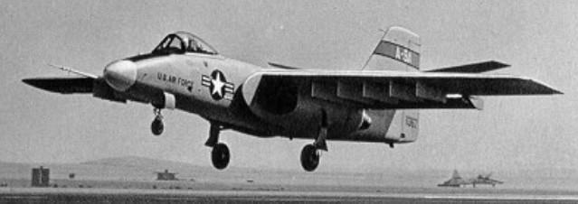
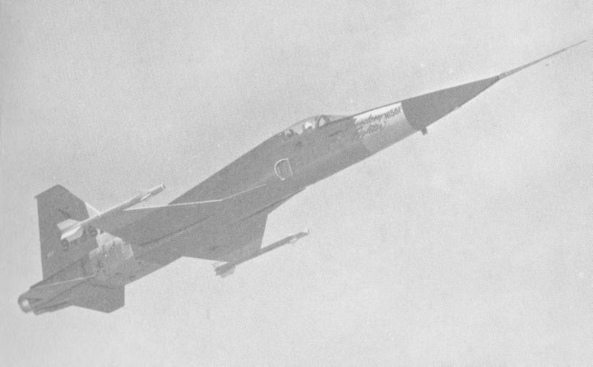
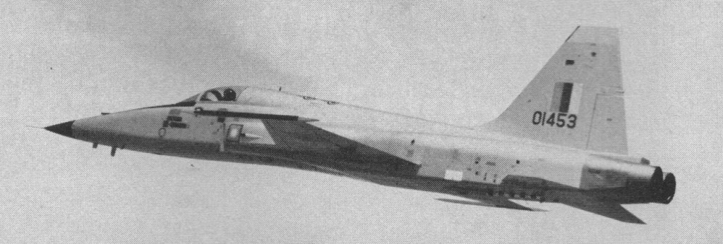
A team under Welko Gasich designed the N 156F in the mid 1950s as an economical, light fighter, cheaper to buy and operate than the large Mach 2 designs then being constructed. The Department of Defense showed little interest, but a two seat trainer version (at first for the Navy, later the USAF) bore fruit and was produced in quantity as the T 38 Talon. This provided an underpinning for the N 156F, which after various changes was released to manufacturing in late 1957, Northrop deciding to build three. The first, by this time called the Freedom Fighter, flew on July 30, 1959. The prototype had a Department of Defense (Air Force) serial number but no national markings. On April 25, 1962, the US government announced that it was ordering the aircraft into quantity production as the standard fighter to be supplied through the Military Assistance Program to Allied and friendly nations. Since then further contracts have followed, paid for by the recipient governments.

N-156F

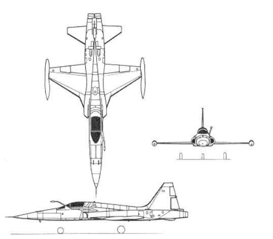
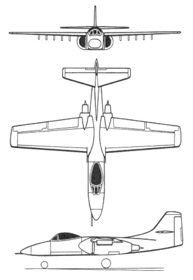
The low wing is swept back 25 degrees, with ailerons at mid-span, and trailing-edge flaps inboard. Full span leading-edge flaps and a conventional rudder is fitted, and all-moving tailplane. Two air-brakes are under the centre of the area-ruled fuselage. The tricycle undercarriage has a single wheel on each unit. The mains retract inward into the fuselage and the nose wheel retracts forward.

Redesignated F 5A (single seat) and F 5B (tandem dual control version), the Freedom Fighter began to come off the production line in 1963. Powered initially by two General Electric J85 13 engines each rated at 1383 kg (3050 lb) static thrust with full afterburner, the F 5A was a simple machine with no radar other than a ranging set for the two 20 mm (0.79 in) Pontiac M 39 cannon mounted above the nose.

1966 Northrop F-5B

Northrop F-5 Article

Total internal tankage was 2200 litres (484 Imperial gal), and two Sidewinder air to air missiles could be carried on the wing tips in place of area ruled (Coke bottle shape) drop tanks. Early in development five further hard points were added for a total external load of 2000 kg (4410 lb), the total load of ordnance of all kinds, including guns and ammunition, being 2812 kg (6200 lb).

More than 1000 of this first generation F 5 series were produced, including more than 300 built under licence in Canada, Spain and Taiwan. Canadian aircraft, assembled by Canadair incorporated parts built in the Netherlands in a two nation production programme, with J85 CAN 15 engines built by Orenda. In all except the first production version, the 13 engines were rated at 1850 kg (4078 lb) thrust, except for the CF 5 (Cana¬dian) and NF 5 (Netherlands) versions in which the rating was 1950 kg (4299 lb).

Recipients of these F/CF/NF 5A, B, D and G aircraft included Brazil, Canada, Ethiopia, Greece, Iran, Jordan, South Korea, Libya, Malaysia, Morocco, the Netherlands, Norway, Pakistan, the Philippines, Saudi Arabia, Spain, Taiwan, Thailand, and South Vietnam. The USAF also bought a small number to equip a foreign customer training squadron at Williams Air Force Base, and in 1965 also bought one squadron of single seat F 5A aircraft for evaluation in South Vietnam. The equipment fitted was varied for richer customers, and eventually included inertial navigation for Saudi Arabia and various changes to improve short field performance including increased wing incidence, two-position nose gear, arrester hook, provision for ATO rockets and uprated engines. These customers options were specified by Canada, the Netherlands and, except for uprated engines, Norway.

In April 1964 it was reported Norway had confirmed it will purchase 64 F-5A, with option to buy 20 more. The initial order came to $75 million, including spares and training cost. Deliveries were to be made in 1966-67.

1966 Vietnam F-5

In 1969 the US government held a competition for a successor to the F 5 called IFA (International Fighter Aircraft). Northrop had already fitted an F 5 with two of the more powerful J85 GE 21 engines, each rated at 2227 kg (4910 lb) thrust, and fully investigated the improved performance envelope thus obtainable. It proposed an improved F 5, called F 5E Tiger II, as the IFA, and this won the competition in November 1970. The F 5E has a broader fuselage increasing fuel capacity and wing span a redesigned wing with leading edge manoeuvre flaps, based on an earlier flap fitted to the NF 5A and B, positioned by a switch on the pilot’s throttle working in conjunction with the landing flaps on the trailing edge. It also has large wing root leading edge extensions, Emerson APQ159 X band radar, hard points for a total external load of 3175 kg (7000 lb) and considerably altered and enhanced avionics. Provision is made for a detachable probe for inflight refuelling, and a further list of customer options includes ATO rockets, antiskid brakes (the arrester hook is standard), the ‘FR’ nose, chaff/ECM pods, improved ejection seats and a wide range of special target sensing or designations, weapon guidance and countermeasure kits. The first F-5E was flown in August 1972

By 1978 more than 1000 F 5Es and tandem seat F 5F Tiger IIs had been delivered, and orders had been placed for some 1500 from Brazil, Chile, Ethiopia (supplied by Iran after a US embargo), Iran, Jordan, Kenya, Malaysia, Morocco, Peru, Philippines, Saudi Arabia, Singapore, South Korea, Switzerland, Taiwan, Thailand, Tunisia and South Vietnam. In February 1978, the US government agreed to sell 50 (probably a mix of Es and Fs) to Egypt ‘as a reward for President Sadat’s peacemaking efforts’. Further aircraft had been supplied to the USAF and US Navy for use in DACT (Dissimilar Aircraft Combat Training), the F 5E taking the part of aggressor’ MiG 21 fighters which it resembles in size and to some degree in characteristics. The tandem seat F 5F, of which some 100 have been delivered, has a longer fuselage, a single gun and reduced gross weight.

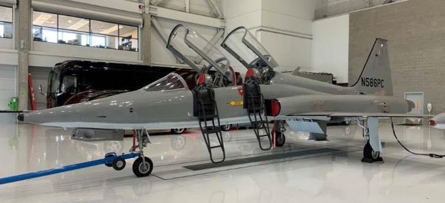
Derived from the earlier F-5A/B Freedom Fighter, the F-5E/F, powered by two 22.24kN General Electric J85 turbojets, first flew on August 11, 1972. Its armament comprises twin 20mm cannon, two AIM-9 Sidewinder, plus up to 3,l75kg of stores on one under-wing and one under-fuselage hard-points. Development of a two-seater conversion trainer counterpart of the F-5E Tiger II was approved early in 1974, and the F-5F Tiger II (73-0889) first flew on 25 September of the same year. The airframe is basically that of the F-5E lengthened by 3 ft 6.5 in (1.08 m) to allow the insertion of a second ejector seat, displays, and controls under a lengthened canopy. Though one of the F-5E’s two 20-mm cannon is removed, the F-5F still has the F-5E’s fire-control system with APQ-157 multi-role radar, and retains all five hardpoints for full combat capability. Some aircraft have an inertial navigation system and provision for a laser designator pod. About 200 F-5Fs were produced, and such aircraft serve with most F-5E operators. Many aircraft are being updated in a series of programs concerned mostly with the F-5E.

1975 delivery of F-5E to Royal Malaysian Air Force

The F-5E/F has also been produced under licence in South Korea, Switzerland, and Taiwan.

The Northrop F-5 Freedom Fighter/Tiger family has also been developed to perform photographic reconnaissance duties; approximately 100 examples of the RF-5A and RF-5E Tigereye have been built to 1984. The first and thus far most numerous reconnaissance model to appear was the RF-5A, 89 examples of which were constructed by the parent company between 1967-72. Featuring a nose-mounted battery of four KS-92A cameras, the RF-5A entered development in October 1963 in response to a US Air Force directive calling for a daylight tactical reconnaissance model of the Freedom Fighter for supply to friendly nations as part of military assistance and foreign military sales programmes. The RF-5A flew for the first time during May 1968, deliveries beginning during the following month with the initial aircraft going to Iran, which received 13 production examples as part of the military aid programme then in being, Subsequent customers comprised Turkey (20 aircraft), South Vietnam (10), Thailand (4), Greece (16), South Korea (8), Morocco (2) and Norway (16) before production of this model ceased in June 1972.

In addition to those aircraft produced by the parent company, the Freedom Fighter was also built under licence in Spain, 17 examples of the reconnaissance model known locally as the SRF-5A being completed by CASA. Many of the 89 CF-5As, 75 NF-5As and 2 seat CF-5Ds completed by Canadair for service with the armed forces of Canada, the Netherlands and Venezuela also featured latent reconnaissance capability, being fitted with camera noses. A total of 204 CF-5s were produced.

More recently, Northrop developed the RF-5E Tigereye for reconnaissance duties and this is a rather more sophisticated machine based on the F-5E Tiger II and using up to six cameras or infra-red scanners on quick-change pallets which can be inserted into the extended nose. Making its maiden flight on 29 January 1979, the RF-5E has thus far failed to find a ready market, the only customers being Malaysia, which took delivery of two during 1983, and Saudi Arabia, which has ordered 10. Malaysia operates two Northrop RF-5E Tigereyes on reconnaissance duties, equipped with Sidewinder air-to-air missiles on the winglips for protection. The type features an arrester hook in common with most US fighters.

Production of the F-5E/F light tactical fighter ended in 1986, and the last two aircraft were handed over to Bahrain on January 16, 1987. A total of 2,610 F-5s of all models were built over a 24-year period, includ-ing more than 1,400 F-5E/F Tiger IIs and RF-5E Tigereyes.

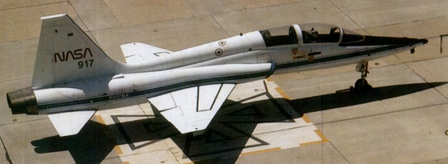
NASA employed a single F-5E airframe with a revised, deeper fuselage for experimentation in DARPA’s “Shaped Sonic Boom Demonstration” program. The airframe survived its testing and became a permanent fixture at the Valiant Air Command Museum in Florida.

A further development, the F-5G, became the Northrop F-20.

Gallery

N-156F
Engines: 2 x General Electric J85-GE-5, 3850 lb
Wingspan: 26 ft 5 in
Wing area: 171 sq.ft
Length: 43 ft 1 in
Height: 13 ft 1 in
Wheel track: 10 ft 10 in
MTOW: 16,110 lb
Internal fuel: 500 Imp.Gal
Max speed: 990 mph at 36,000 ft / M1.5
Cruise: 560 mph at 36,000 ft
Max ROC: 28,000 fpm
Max range: 2100 miles
Hardpoints: 5 + 2 wingtip

F-5A
Engines: 2 x GE J85 turbojet
Span: 7.70 m (25 ft 3 in)
Length: 14.38 m (47 ft 2 in)
Gross weight: 9379 kg (20 680 lb)
Maximum speed: 1489 km/h (925 mph)
External load: 2812 kg (6200 lb)
Seats: 1
Armament: 2 x 20mm cannon

RF-5A
Type: single-seat tactical reconnaissance aircraft
Powerplant: two General Electric J85-GE-13 turbojets, 1851 kg (4,080-1b) afterburning thrust
Maximum speed at 10975 m (36,000 ft) 1489 km/h (925 mph) or Mach 1.4
Combat ceiling 15240 m (50,000 ft)
Range w/max.payload: 592 km / 368 miles
Max range 2595 km (1,612 miles)
Empty weight 3667 kg (8,085 lb)
Maximum take-off weight 8952 kg (19,736 lb).
Span 7,70 m (25 ft 3 in)
Length 14.38 m (47 ft 2 in)
Height 4.01 m (13 ft 2 in)
Wing area 15.79 sq.m (170 sq ft)

F-5B
Span: 7.70 m (25 ft 3 in)
Length: 14.12 m (46 ft 4 in)
Gross weight: 9300 kg (20 500 lb)
Maximum speed: 1424 km/h (885 mph)
Seats: 2

F-5D
Span: 7.70 m (25 ft 3 in)
Length: 14.12 m (46 ft 4 in)
Gross weight: 9300 kg (20 500 lb)
Maximum speed: 1424 km/h (885 mph)

F-5E
Span: 8.13 m (26 ft 8 in)
Length: 14.73 m (48 ft 31 in)
Gross weight: 11192 kg (24675 lb)
Maximum speed: 1704 km/h (1060 mph)

F-5E Tiger II
Engines: 2 x J85 GE 21 reheat 44.5 kN
External load: 3175 kg (7000 lb)
Span: 8.1 m
Length: 14 m
Wing area: 17.3 sq.m
Empty wt: 4410 kg
MTOW: 11,215 kg
Warload: 3175 kg
Max speed: 1.64 Mach
Initial ROC: 10,515 m / min
Ceiling: 15,790 m
TO run: 610 m
Ldg run: 762 m
Combat radius lo-lo-lo: 220 km
Fuel internal: 2563 lt
Air refuel: Yes
Armament: 2 x AAM, 2 x 20 mm
Hard points: 5 + 2 wing tips

F-5F Tiger II
Engines: two 5,000-lb (2,268-kg) reheated thrust General Electric J85-GE-21 B turbojets
Maximum speed 1030 mph (1,658 km/h) or Mach 1.56 at 36090 ft (11000 m)
Initial climb rate 32900 ft (10030 m) per minute
Service ceiling 50800 ft (15485 m)
Radius 599 miles (964 km)
Empty weight 10,576 lb (4,797 kg)
Maximum take-off 25,152 lb (11,409 kg)
Wing span 26 ft 8 in (8.13 m)
Length 51 ft 4 in (15.65 m)
Height 13 ft 1.75 in (4.01 m)
Wing area 186.0 sq ft (17.29 sq.m)
Armament: one 20-mm cannon, and up to 7,000 lb (3,175 kg) of disposable stores

Canadair CF-5 Mk.2
Engine: 2 x General Electric/Orenda J-85-15, 4000 lb
Wing Span: 25ft 10in
Length: 47ft 2in
Height: 13ft 2in (4m)
Speed: 1,150 miles/hr – mach 1.3
Armament: two 20mm Cannons 6,200lbs bombs, rockets & missiles

Northrop T-38 Talon / N-156T

To meet a US government requirement for a high-performance lightweight fighter that would be suitable for supply to and operation by friendly nations via the Military Assistance Program, Northrop began the private-venture design of such an aircraft in the mid-1950s, identifying it as the Northrop N-156.

This initial design concept was to form the basis of a family of aircraft, including a supersonic trainer which had the company designation N-156T. Three YT-38 prototypes were ordered in December 1956, this number being increased to six in June 1958, and the first of them was flown on 10 April 1959.

Northrop T-38 Talon Article

Cantilever low wing monoplanes with slender area ruled fuselages, the first two prototypes were each powered by two 953kg thrust non-afterburning General Electric YJ85-GE-1 turbojets, but the remainder of this first batch had YJ85-GE-5 engines with an afterburning thrust of 1633kg. The first to receive the T 38, in 1962, was the 3560th UPT Wing at Webb AFB, Texas. Testing with these latter engines resulted in an initial contract for the T-38A Talon, the first of them entering service with the USAF’s 3510th Flying Training Wing, at Randolph AFB, on 17 March 1961, powered by two 3,850 lb thrust General Electric J85 GE 5 turbojet engines. The aircraft boasts a 720° per second roll rate.

The Talon, which seats instructor and pupil in tandem on ejection seats and has a fully powered control system, has gained one of the best safety records of any supersonic aircraft in USAF service. As a result, when production ended in early 1972 a total of 1,187 T-38s had been built for the USAF. The US Navy acquired five from the USAF, and three of these remained in service with the Test Pilots School at Patuxent River.

Also supplied through the USAF and operated by the German Luftwaffe were 46 used for pilot training in the US. Only export customer was Portugal who received two batches of six Sidewinder-equipped ex-USAF aircraft in 1977 and 1981 to replace F-86 Sabres used in the dedicated air defence role but doubling as advanced pilot trainers.

NASA also acquired a number from Northrop, using them as flight-readiness trainers for astronauts. Reported in 1965, fifteen were acquired, replacing Convair F-102 Delta Daggers.

The designations AT-38A and NT-38A were allocated to two T-38As following their conversion for evaluation as an attack trainer and research/ development aircraft respectively. Four of the US Navy’s T-38s converted to serve as drone directors were redesignated DT-38A.

The AT 38B is a lightly armed version serving in the Lead-in Fighter Training role at Holloman AFB, New Mexico. The T-38B has a gunsight and a centerline pylon which can be fitted with a gun pod or bombs. Some 700 of these aircraft remained in service in 1992.

The T-38 Talon were modernised to T-38C standard for redelivery from 1999 by Northrop Grumman. The T-38C employed new, electronic instrumentation.

Several T-38s have made their way back into the U.S. in private hands.

Gallery

T-38A Talon
Engines: 2 x General Electric J85 GE 5 turbojets, 2,500 lbs.t. (1134 kgp) and 3,850 lb (1746 kg) with afterburn
Span, 25 ft 3 in (7.7 m)
Length, 44 ft 2 in (13.46 m)
Height: 3.92 m / 12 ft 10 in
Wing area, 170 sq.ft (15.8 sq.m)
Empty weight, 7,340 lb (3329 kg)
Loaded weight, 11,700 lb (5307 kg)
Max speed, 838 mph (710 kt / 1348 kph) at 36,000 ft (10 973 m)
Cruise, 590 mph (949 kph)
Initial climb, 30,000 fpm (152.4 m/sec)
Service ceiling, 56,800 ft (17 312 m)
Range, 1,267 mls (2039 m)
Seats: 2
U/C & flap limit: 240 kt
Loading: +6.4 / -2.6G

Northrop YA-9

Under the designation Northrop YA-9A, the company built two prototypes (71-1367 and 71-1368) of a single-seat close-support aircraft as the company’s submission for the competitive development phase of the USAF’s A-X close-support aircraft competition in late 1972. Designed by Robert Bratt, Walt Fellers, Don Heinze, and Jerry Huben, the A-9 was a cantilever high-wing monoplane, powered by two 2722kg thrust Avco Lycoming ALF 502 turbofan engines, the first of the prototypes made its maiden flight on 30 May 1972 piloted by Lew Nelson. In competitive evaluation the YA-9A lost out to the YA-10A by Fairchild Republic.

Northrop A-9A 71-1367

Both of the A 9s built were passed on to NASA for further tests and were later retired to museums.

The first YA 9A built, 71 1367, first flew on May 30, 1972 and at the end of its military career was put on display at the Castle Air Force Base Museum, until its move back to Edwards.

In the storage yard at Edwards AFB on April 7, 2006. Previously on display at Castle AFB

Gallery

Engines: 2 x Lycoming F-102-LD-100, 33.4kN / 7500 lb
Max take-off weight: 18160 kg / 40036 lb
Empty weight: 10318 kg / 22747 lb
Wingspan: 17.7 m / 58 ft 1 in
Length: 16.3 m / 53 ft 6 in
Height: 5.2 m / 17 ft 1 in
Wing area: 54.9 sq.m / 590.94 sq ft
Max. speed: 740 km/h / 460 mph
Cruise speed: 322 mph
Ceiling: 40,000 ft
Range w/max.fuel: 4800 km / 2983 miles
Armament: 1 x 30mm machine-guns, 7264kg of bombs and missiles
Crew: 1

Northrop JB-1 Bat / MX-543

JB-1

As a direct result of Great Britain’s experiences with the German V-1 “buzz bombs,” the USAAF considered the development of similar weapons. The MX-543 program was initiated in September 1942 to use US versions of Frank Whittle’s jet engine (US-named General Electric J31). In late 1943, Northrop was awarded an USAAF contract to design and develop a Flying Wing “Power Bomb”. Under secret Project MX-543, two Northrop Model JB-1 air vehicles were built.

The first airframe built was the Western Museum of Flight’s JB-1 man-carrying glider. Its unusual shape earned it the name “Bat”. Except for the pilot’s cockpit and canopy, the JB-1 glider was the unpowered aerodynamic equivalent of the second version, the jet powered JB-1A. The JB-1 was used to explore the design’s flight characteristics. It was designed to aircraft standards and being made of aluminum and magnesium it was expensive.

The JB-1 piloted version was lifted aloft as a glider by means of a tow aircraft. Tow hitches are at the tips of the two bomb containers. Only one man-carrying JB-1 was built to test the flying qualities of this flying-wing design. The center section of the JB-1 glider version included two stream-lined “torpedo-shaped” bomb containers. The center section was fabricated of formed and welded magnesium alloy plate. The wing panels were made of riveted and spot-welded aluminum alloy sheet with magnesium wingtips. The pilot’s cockpit was located in the space that would be used for the jet engine installations in the unmanned JB-1A powered model.

On August 27, 1943, from Rogers Dry Lake, Northrop test pilot Harry Crosby made the initial glider flight, using airplane tows to get airborne. The machine flew satisfactorily on tow, and very nicely after cast off, but the trouble began when the pilot tried to land. It had a tricycle gear with low pressure tyres which projected just below the nose and the two side excrescences. The ground cushion was so powerful that, no matter what the pilot did, the thing would rise to about 10 feet and then stall ungraciously. The only answer any¬one could discover was to fly it firmly on at high speed.

Following the successful glider flights, the second model JB-1A was equipped with a pair of General Electric Type B1 turbojet engines replacing the pilot.

JB-1A

The JB-1A Power Bomb was designed as a ground-launched, pilotless airplane with a pre-programmed guidance system. This onboard system was to guide the Power Bomb with reasonable accuracy to a target approximately 200 miles away, at which point it was to make a terminal dive into the target zone with its bomb load. The design ordnance consisted of two 2,000-pound demolition bombs, one in each wing root container.

An unmanned JB-1 powered by an improvised General Electric B-1 turbojet with a wing span of 28 feet 4 inches (8.64 m) made its 1st flight from Eglin Field’s Santa Rosa Island, Florida, on December 7, 1944, and crashed 400 yards from the rail launcher.

Later the definitive buzz bomb was built, with a single body housing the propulsive duct and 3,7001b warhead. The 30ft span missile worked very well, but the Pentagon did not put it into the inventory.

Only 10 JB-1 airframes were built. With the successful USAAF flights of JB-2 pulsejet-powered copies of the V-1 flying bomb, the older JB-1 program was “reoriented towards pulsejet propulsion, and the remaining JB-1s were modified or completed as JB-10 missiles. Ford Motor Company provided the copy of the German V-1 pulsejet engine. Only one of the JB-10 variants was completed by the end of the war (with Ford PJ-31-1 pulsejet engine), and 1945 sled launches using 4 Tiny Tim rockets were at Muroc Field and Eglin. Finishing in June 1996, the Western Museum of Flight restored the only remaining airframe as a manned Northrop JB-1 Bat. The Western Museum of Flight’s JB-1 restoration team consisted of Rick Hilton, Alex Von Tol, and Fred Erb.

JB-10

Specifications:

JB-1 Bat
Powerplant: None
Wing Span: 28 ft 4 in
Overall Length: 10 ft 6 in
Overall Height: 4 ft 6 in
Range: 670 miles
Armament: None
Crew: Pilot
Number Built: One

JB-1A Bat
Powerplants: 2 x General Electric Type B1 Turbojet, 400-lb thrust
Wing Span: 28 ft 4 in
Overall Length: 10 ft 6 in
Overall Height: 4 ft 6 in
Launch Weight: 7,080 lb
Launch Speed: 160 mph
Cruising Speed: 427 mph at 5,000 ft
Range: 670 miles
Armament: 2 x 2,000 lb bombs
Crew: None
Number Built: One

JB-10
Engine: 1x Ford PJ-31-1 Pulse Jet, 800 lb thrust
Wing Span: 29 ft (8.8 m)
Length: 12 ft (3.7 m)
Height: 4′ 8”
Weight: 7,080 lb
Maximum Speed: 426 mph
Armament: 1,826 lb War Head of high explosive
Crew: None

Northrop XP-79B

In January 1943, Northrop was awarded a USAAF contract for the design and construction of three prototypes of a highly original rocket-propelled interceptor fighter of all-wing configuration and designated XP-79. By 1944 Northrop had a range of projects stemming from the MX 324, including Ram Wing. This was a true flying wing with tip duct bellows spoilers, and a pilot lying prone to fit within the wing pro¬file and withstand violent combat manoeuvres. To be powered by a single 907kg Aerojet rocket motor, the XP-79 was to have accommodated its pilot in the prone position, but, in the event, development problems with the rocket led to cancellation of the project. However, a contract was placed for the redesign of the fighter for turbojet power, one prototype being ordered as the XP-79B.

It was schemed in various forms but the basic concept was that the wing should have a leading edge of thick magnesium endowing it with exceptional impact strength. Unlike almost every other flying machine in history the XP 79 was planned with mid air collision as a basic design case. Its four 0.50in guns were officially called “secondary”. There were still no powerful rocket motors and Northrop built the XP 79B with two of the new turbojets.

The engines chosen were the 19 inch Westinghouse Navy axials, which as the pre production J30 (model 19B) were each rated at about 1,150 1b / 619kg. This was judged enough to make the 8,670 lb XP 79B a practical proposition, and technically it was a design of exceptional interest. The pilot was accommodated in a modified cradle, stressed for sustained 12g manoeuvres, with an engine close on each side. To overcome the nose gear problem there was “a wheel at each corner”, each leg folding into the wing. After testing with no fin or with a central fin it was decided to fly with a fin above each jet. The aircraft that bore AAF serial 43 52437. It was delivered to Muroc in June 1945 to start testing with Harry Crosby as a test pilot.

Flown for the first time on September 12, 1945, after several days of preliminary tests, an incident marked the beginning of the flight when an Army Air Force fire truck crossed runway. Crosby had time to cut the power to avoid the collision, then he climbed to 10,000 feet. Crosby seemed quite at home, and flew confidently for 15 minutes. He returned to his take-off area by describing a large circle with a particularly high speed (estimated at more than 400 mph). On his second pass over the salt lake, Crosby started a climbing turn, then the Ram Wing went into an agonizingly slow roll and went straight into the ground in “a steep vertical spin”. Crosby was seen jumping at the last moment but was struck by a portion of the plane. His parachute never opened. The cause was attributed to a hard over runaway by the electric trim tab in the lateral control system. As the war was over ramming was dropped.

Northrop XP-79B

Gallery

XP-79B
Wingspan: 11.58 m / 37 ft 12 in
Length: 4.27 m / 14 ft 0 in
Height: 2.13 m / 7 ft 0 in
Wing area: 25.83 sq.m / 278.03 sq ft
Max take-off weight: 3932 kg / 8669 lb
Empty weight: 2649 kg / 5840 lb
Max. speed: 880 km/h / 547 mph
Range: 1600 km / 994 miles
Service ceiling: 40,000 ft / 12 000 m
Rate of climb: 4,000 ft/mn / 1 220 m/mn
Crew: 1

Northrop MX-324 / MX-334

Northrop’s next flying wing project was the MX 324, planned as a research aircraft to pave the way for future flying wing fighters having jet propulsion. It was virtually a low speed glider at first, because no suitable jet power plant existed. It was also remarkably conventional, having ailerons, flaps /elevators, a minimal body and, later, a large wire braced fin. The first example had skids, and the towcar could not pull it off the ground. The second had a jettisonable trolley, which “was not a success.” The third had its own fixed tricycle landing gear, the main wheels having trousers and the nosewheel a spat. The nose leg was offset far to the left. This was because the centreline was occupied by the prone pilot, who had an interesting panel and control arrangement and rested his head in a cushioned sling inside the glass “bubble” nose. The span was about 28 feet.

Northrop went ahead with the project, under Don B Smith, in September 1942. An Army Air Force contract was awarded in January 1943 and John Myers flew the MX 324 as a glider on October 2, 1943.

By this time Northrop was talking with the infant Aerojet Engineering Corporation of Azusa, which had been formed to advance American rocketry. Their first engine planned for a manned aircraft was the XCAL 200. Though the single thrust chamber had but one thrust level, a mere 200 lb, the whole installation weighed 427 lb. This included a tank of monoethylaniline fuel, a tank of red fuming nitric acid oxidant, four gas bottles to feed the propellants, the thrust chamber and a lot of hydraulic and electric control systems. Most of it was still in bits during the first half of 1944. Early in June, the aircraft was trucked to Harper Dry Lake and static-fired on June 20. On June 22 the staked down machine was fired for the full burn time of five minutes. The next day company pilot Harry Crosby taxied under the thrust of the rocket, bringing out the need for “mods”. Finally, at dawn on July 5 Crosby smoothly rose into the cool sky on tow behind a P 38 Lightning. He cast off at 8,000 feet, paused for the tug to clear and then pressed the fire trigger on his miniature control column. It went perfectly.

The MX-334 flew under power for 3 minutes 30 seconds on 22 June 1944. On July 11 Crosby dived under power at about 350 mph to very low level before zooming up almost vertically to 6,000 feet. But the MX 324 was a bit of a dead end until new propulsion systems emerged.

Northrop N-23 Pioneer / C-125 Raider

N-23 Pioneer

Northrop’s postwar model was intended for the less developed parts of the world where airline operations frequently involved short, unprepared runways. The Pioneer was a 36-passenger (or a combination of fewer passengers but more cargo) design with three 800hp (600kW) Wright R-957 C7BA Cyclone engines and a fixed, conventional landing gear. The prototype made its first flight from Hawthorne, California, on December 21, 1946.

Full-span flaps and retractable ailerons, which had been successfully tested on the P-61 Black Widow, enabled the Pioneer to takeoff at its maximum weight of 25,000lb (11,340kg) in less than 400ft (120m) and to land in 600ft (180m). Dual main landing gear wheels could be installed for operation from soft fields. The cruising speed was only 150mph (240km/h), but that was considered sufficient for the short stages on which the Pioneer would operate. After about a year of test flying, the Pioneer was lost when a make-shift dorsal fin failed during yaw tests. By that time, the Pioneer could not compete with the inexpensive military-surplus transports, even with its outstanding short-field performance. Although the Pioneer program was terminated, the basic design evolved into the larger Northrop C-125 Raider for the USAF. 23 were built with 894kW Wright R-1820-99 engines: 13 as C-125A assault transports and ten as C-125B Arctic rescue aircraft.

C-125 Raider

N-23 Pioneer
Engines: three 800hp (600kW) Wright R-957 C7BA Cyclone
Maximum take-off weight: 25,000lb (11,340kg)
TO dist: 400ft (120m)
Landing dist: 600ft (180m)
Cruising speed: 150mph (240km/h)
Capacity: 36-passenger

C-125A Raider
Engines: 3 x 894kW Wright R-1820-99 engines

C-125B Raider
Engines: 3 x 894kW Wright R-1820-99 engines

Northrop N-2B / XP-56

Northrop Aircraft Inc was invited to submit proposals for a new pursuit aircraft (in the R 40C informal Army competition), allotted the designation XP 56, for a single engined pusher. An informal competition initiated late in 1939, the winning contractors being Vultee (XP-54), Curtiss (XP-55) and Northrop (XP-56).

Northrop began to scheme the N 2B in August 1941. A wing very similar to the N-1M, though thinner, was selected for the fighter. On each trailing edge was a single, large elevon, combining the, functions of elevator and aileron. Above each tip was a hinged spoiler for creating drag for yaw control. The fuselage was just a minimal nacelle, with a ventral fin to keep the propeller from hitting the ground.

Armament was to comprise two M 2 20mm cannon and four 0.5in Brownings, grouped in the nose, although this was never fitted. Tricycle landing gear was inevitable, the mainwheels being housed in. the lee of the large ducts that served the engine. Power was provided by a 2,000hp Pratt & Whitney R-2800-29 Double Wasp 18-cylinder radial engine buried in the rear fuselage and driving contra-rotating pusher propellers. The canopy hinged to the right, and for emergency escape the pilot was to jettison not only the canopy but also the propeller, Pratt & Whitney designing a jettison system with explosive cord surrounding the gearbox. The propeller eventually used was a Curtiss, Electric contraprop, with two three blade units. The primary structure was entirely magnesium, welded by the company’s patented Heliarc process (which sur¬rounded the are with inert helium) perfected during construction of this aircraft.

As far as possible it was based on the experience gained with the N-1M. It even retained the down sloping wing tips, though the angle was not acute and the control system was of the latest type with bellows¬ opening split “trim rudders” (i.e., ailerons) used as single surfaces for lateral control and opened into upper and lower spoilers for making properly banked turns. The actuation of these surfaces was novel. Air was rammed in through a forward facing intake on each tip, taken through a duct and diverted by valves to pressurise the bellows when required. In straight and level flight the duct was open at both ends, creating little drag.

At first Northrop tried to stay as close as possible to the pure all wing concept, and planned for the pilot to lie prone, but when the Army began to talk about a prototype contract they made it clear they wanted a regular body with a conventional cockpit. Eventually they purchased two prototypes, ordered on 26 September 1940 and 13 February 1942 respectively, each having quite a fat body of symmetrical streamline form containing a 2,400 h.p. Pratt & Whitney R 2800 Double Wasp engine. Cooling the engine was, as in the N 1M, a major problem. Air was rammed in through large wing root intakes, ducted sharply in to the engine bay and allowed to escape past the baffled cylinders and out via the ejector assisted exhaust ducts. Cooling airflow was assisted by a high speed fan geared up from the engine, but to perfect the installation would have been a very large task. The unpressurised cockpit was immediately ahead of the engine, and the nose was planned for an eventual armament of two 20mm and four 0.50in guns. Elevators were fitted inboard of the tip droops, there was a large delta fin above and below the rear fuselage and the main wheels of the tricycle landing gear were housed in bays immediately behind the cooling ducts.

According to Northrop two prototypes were ordered on September 26, 1940, at a price of $411,000; other observers insist the second was not signed for until February 13, 1942. The first XP 56 was delayed by the decision of Pratt & Whitney to drop the X 1800. The R 2800 Double Wasp was already giving 2,000 h.p. while the, X 1800 did not look like maturing until after the war. The decision, was taken on, July 21, 1941, and Pratt & Whitney had to make a Double Wasp with concentric drive shafts and the jettison device (the R 2800 29), while Northrop had to rearrange, the, engine bay and central wing structure to pick up the big 18 cylinder radial and supply it with air, the latter augmented by a fan and discharged via gills ahead of the spinner. Another change was to alter the anhedral of the outer wing as a result of N-1M testing. Eventually the XP 56 emerged in March 1943. In April test pilot John Myers began taxiing tests and found directional stability unsatisfactory. Especially as speed was increased, the XP 56 by now for some – reason dubbed “The Black Bullet” tended to swerve violently, skidding the, tyres and rocking laterally. At least part of the trouble was due to the; brakes, and a new hydraulic brake system, was fitted to give smoother differential action.

After further cooling and system difficulties, the XP 56 first flew on September 30, 1943. It had been expected that the ventral fin added, to the contraprop side area would prove adequate for weathercock stability, but it was clear that directional stability was almost non existent. A larger upper fin was quickly added over the original, and from then on the handling seemed to be satisfactory. No photographs are known of the modified aircraft. In any case, USAAF 41 786 was soon written off. According to one set of writers it suffered a burst mainwheel tyre. According to another it suffered nose-wheel shimmy, leading to failure of the nose leg. For whichever reason, the aircraft somersaulted and was demolished. Myers broke his back, though his head was saved by the fact he habitually wore his polo helmet.

When the second aircraft, 42 38353, emerged the upper fin was even larger than on the modified No.1 aircraft. A further modification was that the, wingtips now carried bellows-type split ailerons for lateral and yaw control, replacing the upper and lower surface spoilers. Each tip was formed by a large venturi duct which normally sucked the split surfaces closed. For yaw control the surfaces were blown open by a bellows to which ram air from the tip duct was admitted via a diverter valve.

The second Bullet was flown by Harry Crosby from Hawthorne, on March 23, 1944. Though flight characteristics were better than for the first aircraft the engine did not deliver full power, the nosewheel would not lift off until an airspeed of 160 m.p.h. had been reached, and the flight was terminated after 7½ min. On the second flight, with gear retracted, the trim was normal but speeds were below prediction. So concerned were, Northrop at the failure to reach design speeds (the objective was 465 mph at 25,000ft), that they booked a place in the queue for the giant open jet wind tunnel of the NACA at Molfett Field. Meanwhile, testing continued, but on the tenth flight the pilot logged so many shortcomings that it was decided to discontinue further flying.

By this time the XP 56 had been outclassed by such conventional fighters as the P 51, and overtaken by the jet engine. In 1979 No 2 was still intact, held by the Smithsonian.

XP-56
Max take-off weight: 5148 kg / 11349 lb
Empty weight: 3946 kg / 8699 lb
Wingspan: 12.98 m / 42 ft 7 in
Length: 8.38 m / 27 ft 6 in
Height: 2.94 m / 9 ft 8 in
Wing area: 28.52 sq.m / 306.99 sq ft
Max. speed: 671 km/h / 417 mph
Range: 1062 km / 660 miles
Crew: 1

Northrop YB-49

The second and third YB-35 pre-production prototypes were converted into YB-35B aircraft. Their four 3250-hp (242 3-kW) Pratt & Whitney R4360 piston engines were replaced by eight 4000-lb (1814-kg) thrust Allison J35-A-5 turbojets, four jets being grouped in each trailing edge and aspirated through the same arrangement of leading-edge inlets used to supply carburation and cooling air for the piston engines of the original aircraft.

Northrop B-35 & YB-49 Article in XB-35

The YB-35B was redesignated YB-49 while it was being rebuilt, and the first aeroplane flew on 21 October 1947. The second had six 2540kg thrust Allison engines, four buried in the wings and two in underslung pods to increase the volume available for fuel.

Speed was increased dramatically from 393 to 520 mph (632 to 837 kph), but such was the thirst of the turbojets that range was halved. There were also several control problems that made the type unsuitable for use as a free-fall bomber, and it was decided to transform the type into a strategic reconnaissance aeroplane.

In June 1948 the second YB-49 was destroyed with the loss of its five man crew in a crash attributed to structural failure.

Confi¬dence ran high, and the USAF ordered 30 YRB 49s for the long-range reconnaissance role, one of which was to be built by Northrop and, because of that company’s other commitments, 29 by Consolidated Vultee. Even the fatal in flight breakup of the second prototype in March 1950 failed to dampen spirits. The RB-49 offered no real advantages over the B-47 and the new B-52, production was cancelled before the single YRB-49 flew on May 4, 1950.

The YB-35 programme continued for a while with various test airframes, but in October 1949 the whole programme was cancelled and the aircraft were scrapped. The YB 49 made a flag waving trip from Edwards Air Force Base in California to Washington, D.C. at 823 kph (511.2 mph), 160 kph (100 mph) faster than the favoured B 36, but it was too late.

Sole survivor was the six-jet YB-49A, but just four years later this was broken up.

YB-49
Engines: 8 x Allison J35-A-2, 1814 kg (4000 lb) thrust.
Engines: 8 x Allison J35-A-15, 1800kg
Max take-off weight: 96800 kg / 213409 lb
Wingspan: 52.4 m / 171 ft 11 in
Length: 16.2 m / 53 ft 2 in
Wing area: 372 sq.m / 4004.17 sq ft
Max. speed: 930 km/h / 578 mph
Range: 8700 km / 5406 miles
Range: 2800 mi / 4506 km wit 10,000 lb / 4536 kg bombload
Max bombload: 37,400 lb / 16,965 kg
Crew: 6

YRB-49
Engines: 6 x Allison J35 turbojets, 1870kg
Wingspan: 52.4 m / 171 ft 11 in
Length: 16.2 m / 53 ft 2 in
Wing area: 372 sq.m / 4004.17 sq ft

Northrop YB-49
Northrop YRB-49

Northrop XB-35

In 1941 Northrop developed a flying wing design to compete with the Consolidated Model 37. Conceptually more advanced than the B-36, the Northrop XB-35 was a low-drag flying wing with four piston engines in the wings driving contra-rotating pusher propeller units. The type was ordered in prototype form as the XB-35 in November 1941. Powered by four 2237kW Pratt & Whitney R-4360 Wasp Major piston engines driving eight-bladed counter-rotating pusher propellers behind the trailing edges of the 172-ft (52.43m) span wing they could carry a maximum bombload of 56,000 lb (25,402 kg), or a 20,000-lb (9072-kg) bombload over a radius of only 2500 miles (4023 km). The XB-35 was faster than the XB-36 (especially at lower altitude), possessed a usefully higher service ceiling, and was also considerably more agile than the XB-36.

Northrop B-35 & YB-49 Article

There had been problems with the prototype, but these were concerned with factors such as the propeller gears stripped, blade pitch reversed in flight, propellers ‘ran away’, uncontrollable fires started, rather than the structure and flight characteristics of the basic airframe.

The first of 15 YB-35 aircraft ordered in early 1943, flew on 25 June 1946, followed by the second in the following year. With the B-36 slated for production, it was then decided to use the design for the evaluation of jet power in a strategic bomber the production contract was cancelled.

The second and third YB-35 pre-production prototypes were converted into YB-35B aircraft: their four 3250-hp (242 3-kW) Pratt & Whitney R4360 piston engines were replaced by eight 4000-lb (1814-kg) thrust Allison J35-A-5 turbojets, a quartet of the jets being grouped in each trailing edge and aspirated through the same arrangement of leading-edge inlets used to supply carburation and cooling air for the piston engines of the original aircraft.

The YB-35B was redesignated YB-49 while it was being rebuilt, and the first aeroplane flew in October 1947.

Engines: 4 x Pratt & Whitney R-4360 Wasp Major, 2624kW / 3250 hp
Max take-off weight: 76340 kg / 168302 lb
Wingspan: 52.4 m / 171 ft 11 in
Length: 16.2 m / 53 ft 2 in
Wing area: 372 sq.m / 4004.17 sq ft
Max. speed: 605 km/h / 376 mph
Range: 4023 km / 2500 miles
Bombload: 20,000 lb / 9072 kg
Crew: 9

Northrop XB-35