Arrow Active

Designed by A.C. Thornton at Leeds, the Arrow Active I G-ABIX, a single-seat all metal biplane, was first flown in 1931. Powered by a 115 hp Cirrus Hermes IIB engine it had a top speed of 140 mph.

Arrow Active Article

The second aircraft G-ABVE had a 120 hp Gipsy III engine and flew for the first time early in 1932. It was distinguished by a raised top wing and taller undercarriage. G-ABIX caught fire and was destroyed on 20 September 1935, the pilot parachuting to safety.

No other examples were built.

Active II
Engine: 120 hp Gipsy III
Wingspan: 24 ft
AUW: 1325 lb
144 mph

Arnoux 1920 Biplane

Shortly after the war, Arnoux took up his work again. In 1919/1920, he constructed from components of war-time airplanes a tailless biplane ; it was motorized by a 130 hp rotary engine and had vertical rudder surfaces behind the pilot at both sides of the short nacelle. During 1922, a number of successful flights were made with this biplane. After modification to a single-rudder, it was demonstrated with success to the French aviation authorities, and the results of the tests were so promising that the “Société des Avions Simplex” firm was formed for the further development. The biplane was, however, destroyed in a crash in which the pilot, Fétu, sustained severe injuries.

Armstrong Whitworth Sinaia / Siddeley-Deasy Sinaia

The Sinaia was the third and last aircraft design produced by the team led by John Lloyd and F.M.Green at Siddeley-Deasy before they were rebadged by merger as the Sir W. G. Armstrong Aircraft Company. By the time it flew on 25 June 1921 this change had taken effect. It was designed to meet an Air Ministry requirement for a day bomber.

A large twin-engined biplane, its engines were in nacelles mounted on the top of the lower wings and these nacelles were extended rearwards and upwards. Each extension housed a gunner’s cockpit at its extremity, fitted with a gun ring. From these positions the gunners would have been able to defend both sides of the bomber independently.

The Sinaia was a three bay (with struts to the upper wings from the engine nacelles) biplane. The wings carried no stagger and were of equal span, though the lower wing was narrower. There were horn balanced ailerons on all wings. The empennage was of biplane configuration with a balanced elevator on the upper plane and containing three balanced rudders. The square section fuselage placed the pilot’s cockpit well forward of the engines and a third gunner’s position in the extreme, slanted nose. A two-wheeled main undercarriage unit was mounted under each engine.

The Sinaia was powered by two 500 hp Siddeley Tiger water-cooled engines, a new V-12 design produced by combining two straight-6 Siddeley Pumas onto a single crankshaft. This little-tested powerplant proved unreliable and frequent problems with it interrupted the flight trials of the Sinaia.

Two examples were ordered by the Air Ministry but only one, J6858, was completed. By October 1921 the airframe was showing signs of structural problems and the only Sinaia ever built was taken out of use.

Type 103 Sinaia
Powerplant: 2 × Siddeley Tiger V-12, 500 hp (370 kW) each
Wingspan: 86 ft 10 in (26.47 m)
Wing area: 1,823 sq.ft (169.4 sq.m)
Gross weight: 16,000 lb (7,260 kg)
Crew: 4

Armstrong Whitworth Liskin

The prototype Liskin aircraft, the first to be entirely designed and constructed by the Company, was begun in 1919 and was built of wood and canvas.

It first flew from the old Radford Aerodrome at Coventry in 1920 and was shown to the public at the first R.A.F. Hendon display in that year.

Fitted with an A.B.C. Dragonfly air cooled engine, this prototype was the forerunner of a series of aircraft with graduated improvements in engines and general construction.

Engine: A.B.C. Dragonfly, 320 hp
Span: 27 ft 6 in
Wing Area: 247 sq.ft
Fully loaded weight: 2,181 lb
Registration: C 4541

Armstrong Whitworth AW.35 Scimitar

A development of the A.W.16, the A.W.35 Scimitar was powered by a Panther VII engine enclosed by a long-chord cowling and rated at 565hp at 3660m, and a maximum output of 605hp at 4115m. Armament was two 7.7mm Vickers Type E machine guns and provision was made for four 9kg bombs to be carried beneath the lower mainplane.
Two prototypes of the Scimitar were flown in 1933, and these were followed by four production examples for the Norwegian Army Air Force which were delivered at the beginning of 1936. These were powered by the Panther XIA with a maximum rating of 730hp.

Engine: Panther XIA, 730hp
Take-off weight: 1860 kg / 4101 lb
Empty weight: 1276 kg / 2813 lb
Wingspan: 10.06 m / 33 ft 0 in
Length: 7.62 m / 25 ft 0 in
Height: 3.53 m / 11 ft 7 in
Wing area: 24.28 sq.m / 261.35 sq ft
Max. speed: 343 km/h / 213 mph

Armstrong Whitworth Atlas

The Armstrong Whitworth Atlas was designed to replace the de Havilland DH.9A biplane of 1918 as well as the Bristol Fighter of 1916 against the RAF requirements of Specification 20/25. The Atlas design was intended to replace both airframes as the primary RAF “army co-operation” (mission liaison) mount. The Atlas was attributed to an engineering team led by John Lloyd who headed up design at the Armstrong Whitworth Aircraft firm as its Chief Designer.

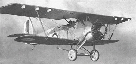
Armstrong Whitworth and Lloyd’s design team initially undertook the Atlas project as a private venture, the prototype first flying on May 10th, 1925. The RAF then accepted the prototype for evaluation against other aircraft and the two-seat Atlas biplane proved a sound design save for some noticeable “sideslipping”. The issue was resolved with the fitting of new metal wings that featured sweepback. However, the new wings degraded the quality of the aircraft’s in-flight handling – then deemed excellent – and now showcased poor stall characteristics as well. As such, automatic slats were added to the wings and sweep was increased to an extent and, in the case of aircraft for the RCAF, the addition of ailerons on the lower wings. This rectified the less-than-stellar handling characteristics caused by the wing change.

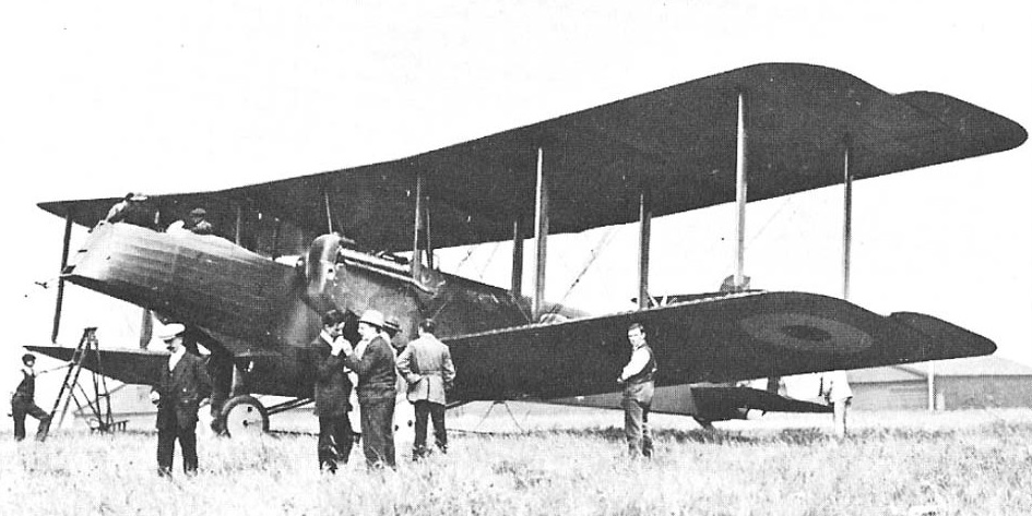
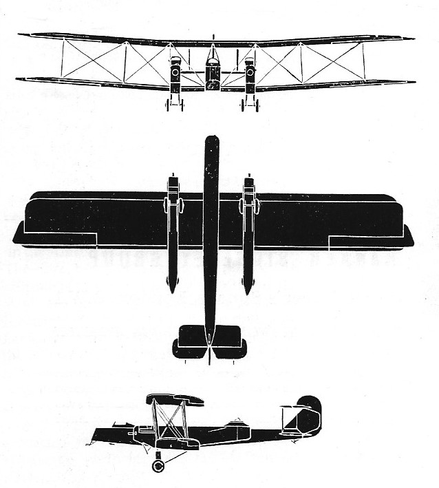
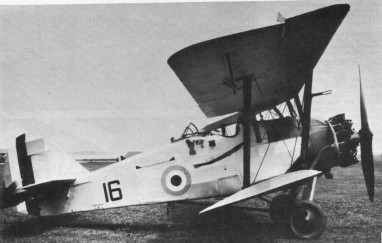
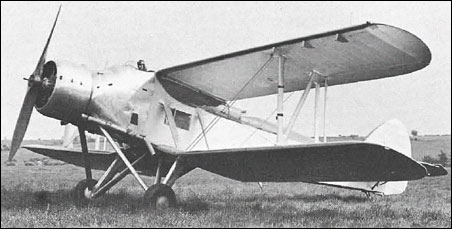
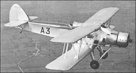
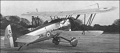
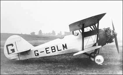
Design was highly conventional for the time. The aircraft mounted its engine in a forward compartment to power the propeller system. The steel tube fuselage (fabric covered) was rather rounded in shape, thicker forward and tapering off at the rear. The wings were of an unequal span, single-bay biplane assemblies made of metal sporting slight dihedral on each unit, moreso in the lower assembly. The pilot sat direct aft of the upper wing assembly in an open-air cockpit with his observer/gunner in an open-air cockpit aft of the pilot. The empennage was relatively conventional in design, featuring a rounded vertical tail fin with a pair of horizontal stabilizers. The undercarriage varied based on sortie need – either a pair of wheels were set in a fixed undercarriage for land-based assignment or a set of long-running pontoon floats could be installed for at-sea work. Either way, the empennage was supported by a simple tail skid made particularly suitable for the land-based model. A hook could be optionally fitted to the fuselage underside to make quick pick-ups of ground messages without having the aircraft be required to land.

Standard armament for the series centered around a pairing of machine guns. A .303in (7.7mm) Vickers type machine gun was in a fixed position set to fire forward. A .303 (7.7mm) Lewis machine gun was mounted on a “Scarff ring” in the rear cockpit for trainable fire against emerging enemy threats from the rear. The flexible Scarff ring was developed in World War 1 by Britain Warrant Officer (Gunner) F.W. Scarff to address the armament needs of a rear gunner faced with the prospect of fighting the enemy from multiple angles from his open-air cockpit. In addition to the machine guns, the Atlas could be fitted with 112lb bombs under the wing elements.

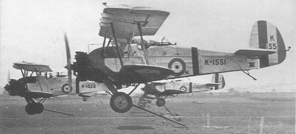
Production of the Atlas began soon after with the aircraft formally introduced for service with the British Royal Air Force in 1927, an initial production batch numbering 37 aircraft. The Atlas entered service with 13 Squadron and 26 Squadron immediately and was eventually fielded with the overseas 208 Squadron out of Heliopolis, Egypt in 1930. It served in the mission liaison role – as well as trainer and communications – up until she was retired in 1935.

The initial production model became the Atlas I and some 271 examples were delivered to the RAF. Production lasted from 1927 to 1933 to which 478 were ultimately produced. 175 were dual-control advanced trainers.
The Atlas Trainer served as a dual-control mount in the training of future Atlas pilots.

These aircraft were to remain in service until 1934 in the army cooperation role, and as advanced trainers and communications aircraft into 1935.

Beyond British use, the Atlas was in the inventories of Canada, Egypt and Japan. The Atlas was eventually superseded by the Hawker Audax, based on the Hawker Hart biplane, and its trainer derivatives were themselves replaced by the Hawker Hart Trainer.

The Atlas II soon appeared as an improved Atlas model with more output from its Armstrong Siddeley Panther IIA engine of 525 horsepower/399kW, radio, message pick-up hook and cameras. However, the RAF elected to go with the competing Audax design and 15 of this model were delivered to the Chinese Air Force. Ajax represented Atlas I models with slight variations and only 4 were ever built for the RAF. Aries was a proposed and improved Atlas I model with slightly larger surfaces and overall dimensions while also being made easier to maintain in the field. However, only one was ever completed. The EAF Atlas was an export product for the Greek Air Force (Hellenic Air Force) that primarily differed in its selected engine, propeller and wing assemblies. At least 10 of this model were locally built by EAF (State Aircraft Factory) in Greece after 1931.

The last Armstrong Siddeley Atlas in RAF service was fielded by 208 Squadron, which replaced their aircraft with the newer Hawker Audax in 1935. Privately-held Atlas aircraft operated until 1938.

Atlas Mk I
Engine: 1 x Armstrong Siddeley Jaguar IVC, 450hp / 298kW.
Length: 28 ft 6.6 in (8.68m)
Wing span: 39 ft 6.6 in (12.04m)
Height: 10 ft 6 in (3.20m)
Empty Weight: 2,557 lbs (1,160kg)
Maximum Take-Off Weight: 4,028 lbs (1,827kg)
Endurance: 3.5 hr
Maximum Speed: 142mph (229kmh; 124kts)
Maximum Range: 400miles (644km)
Service Ceiling: 16,798ft (5,120m; 3.2miles)
Armament: 1 x 7.62mm Vickers mg, 1 x 7.62mm Lewis mg position
Up to 4 x 50kg bombs underwing
Crew: 2
Hardpoints: 4

Atlas Mk II
Engine: 399kW Panther IIA

Armstrong Whitworth AW.19

Air Ministry Specification G.4/31 called for a General Purpose aircraft, capable of level bombing, army co-operation, dive bombing, reconnaissance, casualty evacuation and torpedo bombing. The Vickers Type 253 won against the Fairey G.4/31, Westland PV-7, Handley Page HP.47, Armstrong Whitworth AW.19, Blackburn B-7, Hawker PV-4 and the Parnell G.4/31.
One prototype, first flown on 26 February 1934. No production.

Engine: 1 x 810hp Armstrong Siddeley Tiger VI
Take-off weight: 3969 kg / 8750 lb
Empty weight: 1950 kg / 4299 lb
Wingspan: 15.14 m / 49 ft 8 in
Length: 12.85 m / 42 ft 2 in
Height: 3.96 m / 12 ft 12 in
Wing area: 60.78 sq.m / 654.23 sq ft
Max. speed: 262 km/h / 163 mph
Ceiling: 6400 m / 21000 ft

Armstrong Whitworth AW.16

The Specification 21/26, issued by the Air Ministry’s Directorate of Technical. Development (DTD) on September 30, 1926, called for a “Single Seater Fighter Ship¬-plane for use from HM ships,” fitted with a land undercarriage which could be replaced by floats, and vice versa, within half an hour. The aircraft, which was to have an all metal structure but could be fabric covered, was to be suitable for launch from a catapult and for taking off from and alighting on the deck of an aircraft carrier.
Engines specified were the air cooled Bristol Mercury radial giving 550hp at 2,000rpm or the water cooled Rolls Royce Falcon X giving 480hp at 2,300rpm. A metal propeller was specified.
There was to be tankage for 74 gallons of fuel, plus an easily removed 20 gallon auxiliary tank and a gravity tank of sufficient capacity to allow half an hour’s flight at full power at ground level. An 11 gallon oil tank was to be provided if the Mercury engine was used, or an 8.5 gallon oil tank and a 2.5 gallon reserve water tank for the Falcon.
Alternative exhaust systems for day or night flying were required, and were to be easily changed.
Additional equipment to be carried during the acceptance flights weighed 5581b and included a Vickers 0.5in gun and 300 rounds, a Vickers 0.303in gun and 600 rounds, a rocket launching (R/L) tube and six bombs, and flotation gear. A second 0.303in gun with 600 rounds was to be provided for if the 0.5in gun was not available in time.
Minimum performance requirements with this load, using the Mercury, called for a horizontal speed of 132kt (152mph) at 10,000ft and a service ceiling of 23,000ft. With the Falcon X the figures were 127kt (146mph) at 10,000ft and 22,000ft. The length of run to take¬off was not to exceed 47ft in a relative wind of 28kt (32mph), and the aircraft was to become airborne at a speed of 55mph when catapulted in still air. The suitability for launching from a catapult or alighting on the deck of an aircraft carrier was “of first importance”, and the aircraft had to be capable of taking off from a turret or cruiser platform.
Despite the emphasis placed on the machine’s naval use, it was stressed that: “The aircraft is to be designed primarily as a landplane fighter and qualities required for this work are not to be sacrificed in order to improve its characteristics when equipped with the float alighting gear”.
A limit of 35ft was put on the wing span, the overall length was restricted to 23ft, the height was not to exceed 14ft 9in. Quick and easy removal and erection of the wings was specified, with the ability to remove the wing structure completely in ten minutes and replace it in fifteen minutes.
Tendering for this demanding specification were Armstrong Whitworth, which offered the AW XVI; Fairey, with the Flycatcher II; Gloster, which tendered the Gnatsnapper; Hawker, which offered the Hoopoe; Vickers, with a modified version of its Type 141 Scout; and George Pamall & Co.
Developed as a private venture to meet the requirements of both N.21/26 and F.9/26, the A.W.16 appeared in 1931. Two prototypes were flown. The first conforming to N.21/26 and the second to F.9/26, both being initially powered by the geared and supercharged Panther IIIA of 540hp. The second prototype was re-engined with a 565hp Panther VII during the course of trials at the A & AEE in 1933. Eighteen production examples of the A.W.16 were produced late in 1931, 17 of these for delivery to the Chinese Kwangsi Air Force and one being used as an engine test bed before being passed to the Alan Cobham circus. Armament comprised two 7.7mm Vickers machine guns.

Engine: Panther IIIA, 540hp
Take-off weight: 1597 kg / 3521 lb
Wingspan: 10.06 m / 33 ft 0 in
Length: 7.62 m / 25 ft 0 in
Height: 3.50 m / 11 ft 6 in
Wing area: 24.24 sq.m / 260.92 sq ft
Max. speed: 322 km/h / 200 mph