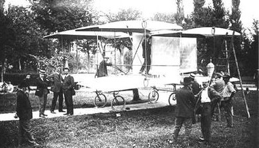
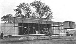
Built in the town of Cortile, near Parma, the A.B.C. biplane of Prof. Bassoli and G. Corni, an engineer and a mathematician, flew just once – ending in a crash – on August 21, 1910.
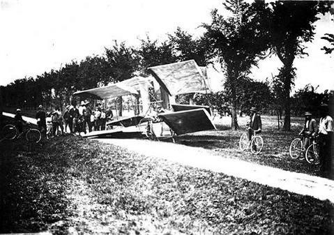
Built in the town of Cortile, near Parma, the A.B.C. biplane of Prof. Bassoli and G. Corni, an engineer and a mathematician, flew just once – ending in a crash – on August 21, 1910.
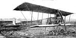
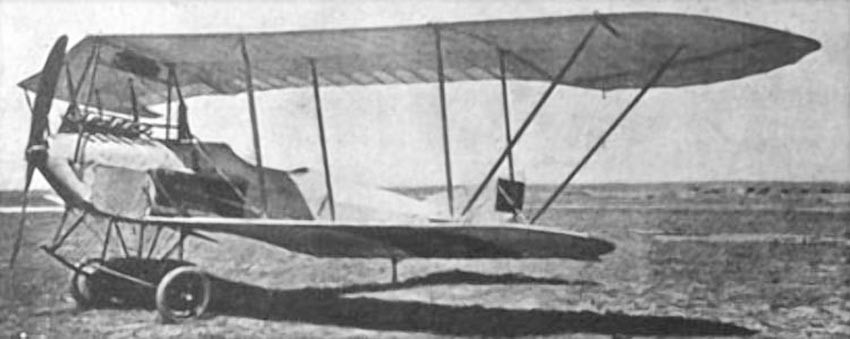
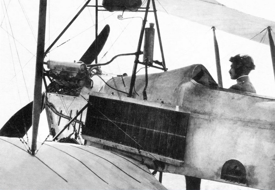
The 1911 Bastier biplane was designed and built by Bastier in France.
Span: top 32’10” bottom 23′
Length: 31’2″
Weight: 992 lbs
Speed: 50 mph
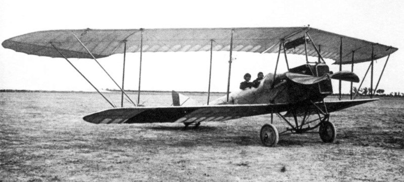
The 1911 Barucki II biplane was designed and built by Eng.Barucki in Poland.
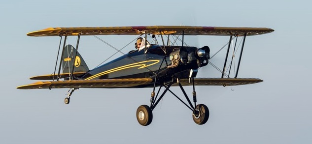
The Skyotë is a plans-built aircraft design dates back to the 1970s when it was created by Pete Bartoe. His goal was to create a plane that was affordable and easy to fly, with enough performance to be competitive at the International Aerobatic Club’s Intermediate level.
Bartoe met his design goals, and the delightful handling qualities of the Skyotë were praised by R.A. “Bob” Hoover in a flight report that appeared in the December 1976 issue of Sport Aviation.
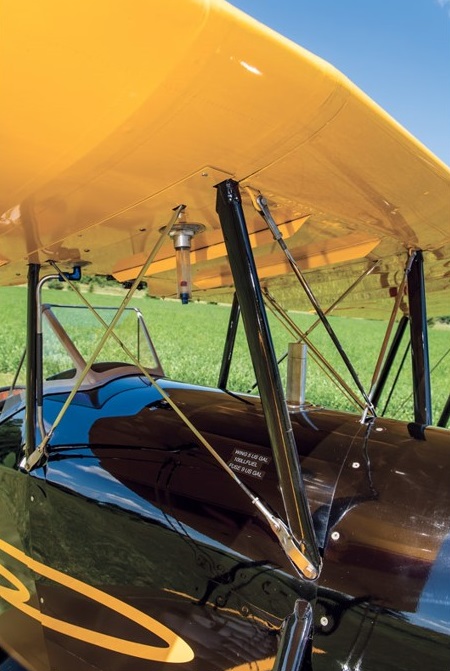
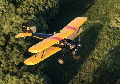
The Skyotë uses a biplane planform, with a swept wing. It has a single seat, tube-and-fabric fuselage with an all-aluminum structure, and fabric-covered wings stressed for +9/-6 G. Weight and performance qualify it for the Light Sport category, and it uses a Continental O-200 engine.
The airplane is not a typical plans-built homebuilt. Bartoe did not design it with homebuilding in mind; his intention was factory production.
Because the goal was good aerobatic performance on minimum horsepower, each part is optimized for its purpose. As a result, parts are made from six gauges of aluminum, seven gauges of steel, and three gauges of stainless steel. The 7.2-degree wing sweep looks and performs great, but is hard to build. Brackets in the wings have left, right, top, and bottom positions, so one part can have four different bending configurations depending on what wing location you’re building. The mounting clips for the wing ribs have an acute angle on one side and an obtuse angle on the other side.
Although the Skyotë didn’t make it to production, Bartoe sold around 100 sets of plans. Twelve airplanes have been completed from the original plans, but about half of those were factory prototypes. The first, N8XX, first flying on 23 April 1976 powered by a 90hp Continental C-90F.
John Roberts was one of those people who ordered a set of plans. But when he received them, it didn’t take long to discover why only five builders had completed their airplanes after nearly 40 years—the drawings were incredibly complicated, and the skill level required was way beyond the ability of most potential builders.
Roberts decided to use modern technology to get his plane, Skyotë #88, into the air, as the Tech-Built Skyotë.
Knowing that Pete Bartoe had mathematically calculated all Skyotë dimensions to an accuracy of three decimal places for all three axes led John to see the combination of Skyotë plans and 3D CAD as a better way to have the Skyotë he wanted.
While learning Geomagic 3D CAD software, John selected parts from Bartoe’s drawings and created CAD models for each part. Over time, he ended up with more than 150 drawings depicting nearly 600 parts that needed to be fabricated for the Skyotë.
The software’s 3D modelling feature produces assembly drawings that are very easy to understand. By assembling the parts in “virtual space,” you can be sure that all of the parts will fit together correctly.
The CAD program also confirmed the accuracy of Bartoe’s original calculations. With a total of nearly 1000 pieces in the Skyotë and tens of thousands of holes, John discovered only one small error—a single hole was off about 1/32 inch. That discrepancy has been corrected.
To convert his .dfx files into parts a waterjet cutting process cut about 600 flat metal parts to make fittings for the wings and fuselage.
In the wings there are three compression struts between the front and rear spars, along with drag and anti-drag wires, and one tubular brace out at the tip.
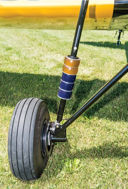
The fuselage is welded steel tube construction with fabric covering. The standard gear uses bungee shocks, and by all reports, it works just fine. A shock strut that uses urethane donuts with various amounts of stiffness for the Tech-Built Skyotë is simple to adjust the amount of bounce, and the donuts are unlikely to wear out.
Engine: Continental O-200, 100 hp
Prop: Catto 2-blade fixed pitch
Wingspan: 20 ft 0 in
Length: 16 ft 3 in
Empty weight: 656 lb
MTOW: 975 lb
Fuel capacity: 15 USG
Full fuel payload: 229 lb
Cruise: 90 kt
ROC: 1200 fpm
Landing speed: 40 kt
Stall: 38 kt
Takeoff roll: 300 ft
Landing distance: 550 ft
Load rating: +9 G/-6 G
Cabin width: 20.25 in
Seats: 1
Engine: 118hp Lycoming O-235-K2A
Wingspan: 20’0″
Length: 16’3″
Useful load: 297 lb
Max speed: 157 mph
Cruise: 112 mph
Stall: 44 mph
Range: 207 mi
Seats: 1
Jerry Morris has over 20,000 flight hours. He was an Air Force C-130 pilot, flew civilian charter for several years, and then was a captain for Delta Air Lines.
I had an opportunity to fly a Skyotë, and what a blast it was.
Climbing in was really not bad, even for an old guy like me. Left foot in the step on the fuse and swing your right leg up and over, and into the single seat. There is a very sturdy handhold conveniently placed in the center of the upper wing that really helps here. Sliding down in, the cockpit rails are tight, but once settled in, they barely rubbed on my shoulders, and it was really comfortable. The low windscreen proved to be very effective, and the visibility all around was open-cockpit superb. All the controls and switches were very accessible and required no stretching or reaching. Very nice.
The little Continental O-200 had already been run this day, so mags on, throttle cracked, mixture in, and crank away. A couple blades later it was up and running. Everything in the green and off I went.
Visibility was actually pretty good taxiing. Slight S-turning was all that was needed. Toe brakes were hardly needed, and the steering through the rudders was very effective but not twitchy. Runup is standard, and I was ready to go.
The Skyotë is a light plane and even with just 100 hp accelerated quickly. By the time I had the power all the way in, the tail was up and ready to fly. Directional control was not an issue, and I was off. Climbing at 70 brought a solid feel with not too high a pitch attitude and excellent visibility. Once out of the pattern, I went up to a higher altitude to play a little.
This thing turns on a dime. Rudder is required, but not much. I led with just a touch, then aileron, and around we went. Same for rolling out. After just a couple turns, it became second nature. It has very light controls, both roll and pitch, and fingertip pressure is all that’s needed to fly. It was easy to trim with the electric trim on the elevator, but there was not a lot of pitch change to trim out with speed changes.
Slow flight at 60 is easy. With power off and holding the nose up, I started feeling the burble in the low 40s. There was an easy break, and the times I stalled it, it wanted to break ever so slightly to the left. A touch of rudder with center stick, though, and I could keep it level. It was very docile.
Steep turns, wingovers, and hammers are all textbook simple and very honest. All the while I enjoyed the great visibility through the wings that seemed to be placed just right for seeing through.
Back to the pattern with my dancing shoes on. In typical carbureted fashion, carb heat on abeam the numbers. I used 70 on base, and once established on final back to 60 indicated. There’s pretty good drag, so with my usual picture, I carried a tad of power down final. Bleeding off over the numbers in the flare, I three-pointed it at just over 50 indicated. Directional control was great, and visibility just out the side of the cockpit was typical taildragger, with not much over the nose. Carb heat and power in, and off I went again.
Next I tried a wheel landing. Same pattern with just a tad of power to keep the speed up for the touchdown. John’s gear is forgiving and wheelies will be simple with just a few tries. Visibility is great with the tail up, and the rudder is very effective. I went up one more time to the final landing, which was basically a repeat of the first. It three-points very nicely and tracks true down the runway with minimal rudder required. Touching down around 50 produces a nice short landing roll, then back to the barn I went, wearing a big grin.
This little ship is a joy to fly, with fingertip controls that are well balanced. Stable in pitch and roll, it didn’t wander around while I was enjoying the view. And what a view! Flying wires and wings were everywhere, but they were easy to see through. In steep turns, looking behind the top wing gives a great view. On the ground, it’s very honest with pretty good visibility. This is the type of plane that’s made for early-morning or late-afternoon jaunts in the country. And, it’s rumored to do great aerobatics.
Thanks so much to John for letting me fly his pride and joy.
—Jerry Morris
Ron Schreck Flies the Skyotë
Ron Schreck, a current IAC competitor and judge, to give us an evaluation of the aerobatics.
John’s home field is at Rock Hill, South Carolina (KUZA), just a 15-minute flight from my home at Gold Hill Airpark, North Carolina (NC25). I arrived on a calm, clear morning in late October. With temperatures in the mid 50s, I was glad I brought along a leather jacket, scarf and gloves.
John gave me a quick introduction to the simple VFR cockpit. Startup was routine and taxi was uneventful. After a brief runup I rolled out to the centerline of Runway 02. Even with the Catto cruise prop, the Skyotë was airborne before I had a chance to wander far from the centerline. I’m guessing that about 400 feet is all it took to take to the air! I found the climb to be a bit lethargic due to the cruise prop, and I would certainly recommend a lower pitched propeller for those interested in serious aerobatics. John tells me he gets a 10-knot boost in top speed with the cruise prop.
Once at altitude I put the Skyotë through some aerobatics. With no inverted systems and lacking dual seat belts and/or parachute, I avoided negative-G maneuvers. Elevator and rudder are quite responsive throughout the flight envelope. Entry to spins, right and left, was a simple matter of pulling power, waiting for the stall (which comes quickly due to the inherent drag) and applying full left or right rudder for a clean entry. Recovery was rapid, with slight opposite rudder and releasing back pressure. The responsive rudder and elevator also make the Skyotë a champion at snap rolls! I found that about 70 knots is the sweet spot for snap entry. A quick tug on the stick, rapidly followed by generous rudder, and the Skyotë eagerly snaps in either direction quite rapidly. The sweep of both upper and lower wings undoubtedly contributes to such great snaps!
Loops must be quite tight as the airplane decelerates quickly when the nose comes up, and you can find yourself out of energy at the top unless you pull with at least 3.5 or 4 G’s at the start. Here again, a climb prop would help out. Aileron rolls are a two-handed affair in the Skyotë, as the ailerons become quite heavy as airspeed increases. The aircraft rolls nicely, but the stick pressure required is not in keeping with the light pressures required for pitch and yaw control. I would like to see if the addition of spades to the ailerons would help. During non-aerobatic flight, the heavy ailerons do not seem to be so obvious.
Landing is pretty much a non-event. You will likely lose sight of the runway through the final turn, as it is blanked out by the upper wing. It will come back into view on final, and visibility over the nose on final and throughout the flare is no problem. I did a wheel landing on the first pattern with no issues. A three-point is another option, and I found that the tailwheel can touch down first without really trying. John did caution me to carry just a bit of power through the flare to avoid an excessive sink rate as the speed rapidly drops off with the throttle closed. Elevator and rudder control are positive in all landings.
For some serious aerobatics you would want to add inverted systems and dual ratcheting seat belts. A parachute would be required for IAC competition. There is little room for a backpack parachute, and pilots with long torsos may have trouble finding a seat-pack ‘chute that will allow you to get low enough in the seat. A chest-pack ‘chute may be a reasonable solution. Some experimentation with different parachutes and/or some modification to the seat may be in order.
Overall, I found the Skyotë to be a docile airplane that packs a lot of fun in a very small package. It is certainly capable of flying IAC competition aerobatics at the Sportsman level and even at the Intermediate level in the hands of an experienced pilot. My thanks to John Roberts for letting me enjoy his ride.
—Ron Schreck
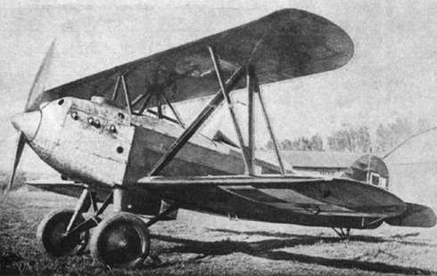
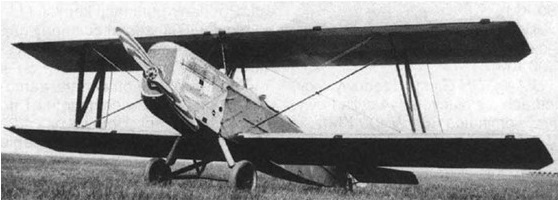
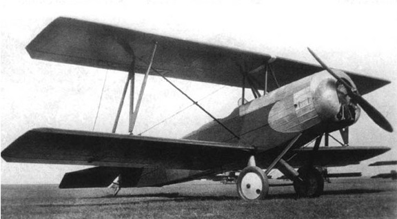
The aircraft was designed by Ryszard Bartel in the Samolot factory in Poznań, as a trainer-fighter plane. A mixed construction biplane. Steel framed fuselage, rectangular in cross-section, canvas covered (engine and upper sections – aluminum covered). Rectangular two-spar wings with rounded ends, plywood and canvas covered. Upper wing span: 7.36 m, lower wing span: 8.10 m. Lower and upper wing halves were interchangeable. Single pilot, sitting in open cockpit, with a windshield. The V8 engine Hispano-Suiza 8Be was modified to lower power output (from 220 hp to 180 hp). Radiator below the fuselage. Fixed landing gear, with a rear skid.
The BM-6 prototype, designated BM-6a, was flown on 8 April 1930 in Poznań. Its advantage was an easy construction and maintenance, according to Bartel’s design philosophy. A distinguishing feature of all Bartels was an upper wing of a shorter span, because lower and upper wing halves were interchangeable (i.e. the lower wingspan included the fuselage width). It first introduced a mixed construction to Bartel’s designs.
After trials, the prototype was modified in July 1930. The prototype was later redesignated BM.6a/II after it was substantially modified. It offered quite good flight characteristics and was capable of aerobatic flight. It was demonstrated in a fighter-plane competition in Bucharest in 1930, along with the similar PZL P.1.

The second prototype BM-6b, with a Wright Whirlwind 220 hp radial engine, was ordered, but work upon it ceased with closure of the Samolot factory in mid-1930. The PWS works, which inherited many of Samolot’s projects, did not continue the project, for it had its own similar design, the PWS-11.
After state trials in 1931, the prototype was used in an advanced training school in Grudziądz, then in an aviation training center in Dęblin.
BM-6a
Engine: 1 × Hispano-Suiza 8Be (modified), 180 hp
Propeller: Two-blade wooden fixed pitch
Wingspan: 8.10 m
Wing area: 17.6 m²
Length: 6.30 m
Height: 2.76 m
Empty weight: 697 kg
Loaded weight: 985 kg
Fuel capacity (fuselage): 168 lt
Useful load: 288 kg
Wing loading: 56 kg/m²
Maximum speed: 192 km/h
Cruise speed: 165 km/h
Stall speed: 85 km/h
Range: 550 km
Service ceiling: 3,800 m
Rate of climb: 4 m/s
Armament: One synchronised 7.7 mm Vickers machine gun in fuselage
Crew: 1

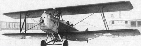
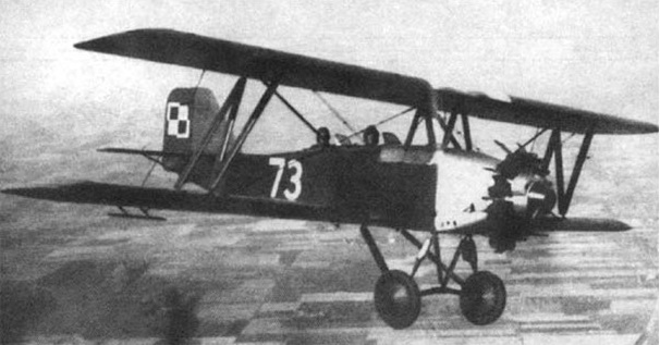
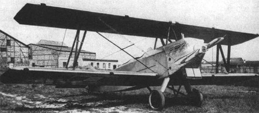
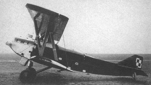
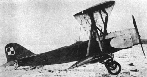
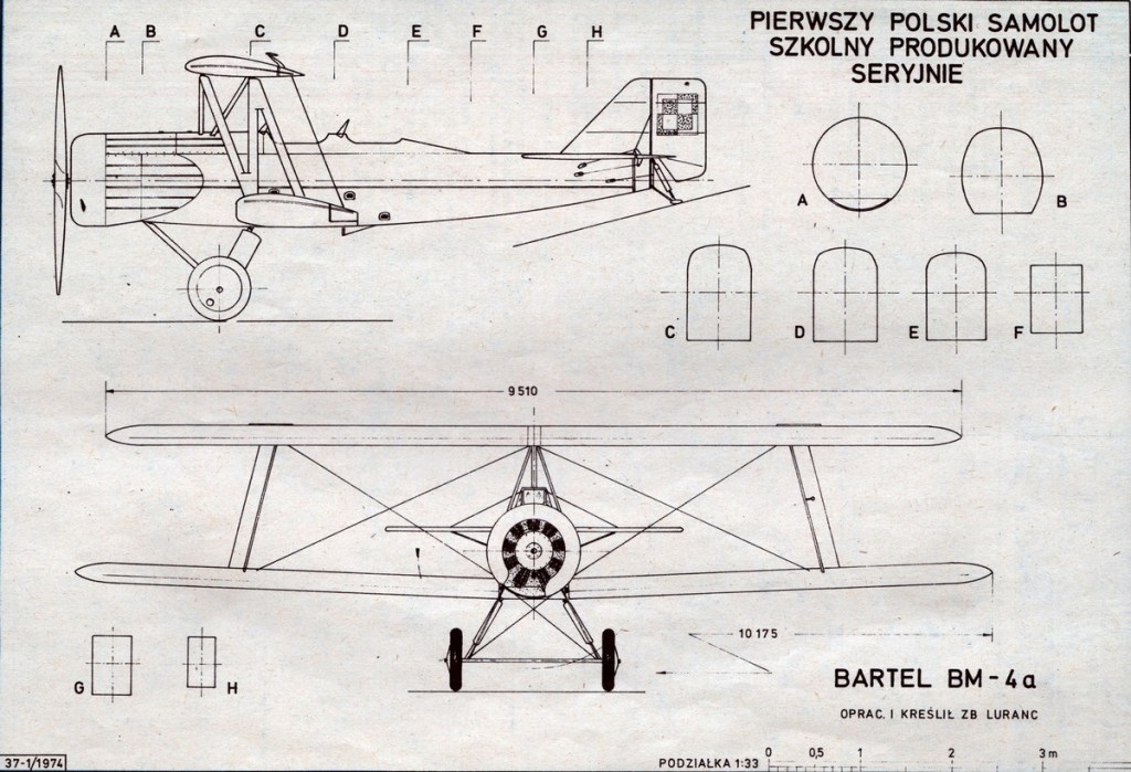
The Bartel BM-5 was designed by Ryszard Bartel with Z. Nowakowski , J. Medwecki , S. Nowkuński in the Samolot factory in Poznań, as an advanced trainer, transitory between primary trainers and bomber or reconnaissance aircraft.
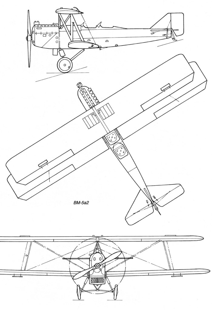
A further development of the Bartel BM-3, it was a wooden construction biplane, the fuselage was rectangular in cross-section, plywood covered (engine section – aluminum covered). Rectangular two-spar wings, plywood and canvas covered. Crew of two, sitting in tandem in open cockpits, with individual windshields and twin controls, instructor in rear cockpit. Fixed landing gear, with a rear skid. Engine in front, with a water radiator below fuselage nose (BM-4a,b,c). Two-blade wooden propeller. Fuel tanks in upper wings and fuselage, capacity: 235-270 t.
The upper panels were identical to the bottom and braced with N steel pipe and wood double links. Upper panels attached to the hull placed on the pyramid of 6 steel pipes and wood. Ailerons on all wings, covered with plywood. The fuselage of rectangular cross-section rounded at the top, was covered with plywood. The front part of the fuselage covered with removable end caps made of aluminum sheet. Trapezoidal tail welded steel pipe, covered with canvas. Tail horizontal casement, supported by struts with steel pipes, vertical tail stiffened profiled of tube.
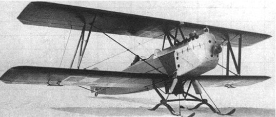
The BM-5 prototype construction started in March 1928 and flown on 27 July that year in Poznań. It had good handling, high stability and spin resistance, which made it a suitable trainer for larger aircraft. The plane was transferred to the military trials, during which some changes were made. During the evaluation flights at the Ławica airport during winter 1929, skis were installed on the aircraft, which proved suitable. A distinguishing feature of all Bartels was an upper wing of a shorter span, because lower and upper wing halves were interchangeable (i.e. the lower wingspan included the width of the fuselage).
The first prototype was designated BM-5a1 and was fitted with a 220 hp (160 kW) Austro-Daimler inline engine. The second prototype, flown on 15 April 1929, was designated BM-5b1 and was fitted with a 230 hp (170 kW) SPA-6A inline engine. Compared with its predecessor, it was heavier by 60 kg due to a larger supply of fuel. Two BM-5b1 were built. It was refitted in August with a 320 hp (240 kW) Hispano-Suiza 8Fb V-engine and redesignated BM-5c1 (it was meant to utilize engine stores from the Bristol F.2 Fighter) and was flight tested on July 29, 1929. Next 20 aircraft of each type were built: BM-5a2, BM-5b2 and BM-5c2.
A disadvantage of most BM-5s were old and faulty engines. From all the variants the BM-5a variant was the heaviest and had the worst performance. Several BM-5a burned in a fire in September 1929. For that reason in 1935 one BM-5 was fitted at the PZL works with a 240 hp (180 kW) Wright Whirlwind J-5 radial engine, produced in Poland (in Polish Skoda Works, then Avia). This variant was designated the BM-5d and 20 of BM-5a and BM-5b were next converted to BM-5d.
On March 20, 1929 a contract was signed for series production of 40: 20 version of the VM-5a and 20 versions of BM-5b, with the first five were equipped with AD225 engine, and the next five – SPA. All production aircraft received the military designation BM-5R2 and deliveries were completed in 1930. These aircraft are sometimes called BM-300. Single copies were in training regiments, squadrons and air camps.
A total of 62 were built.
BM-5s were used in the Polish Air Force for training from 1930, in a central pilots’ school in Dęblin. 5 BM-5c’s were used in Naval Air Unit (MDLot) in Puck. Most were written off in the second half of 1930s and replaced with the PWS-26 in April 1938. Some survived until the German invasion of Poland in September 1939. None survived the war.
Variants:
BM-5a
Austro-Daimler 6-cylinder straight engine, water-cooled, 220 hp (160 kW) nominal power
Wingspan: 11.2 m
Length: 7.81 m
Height: 3.18 m
Wing area: 31.0 m2.
Empty weight: 980-972 kg
Useful load: 370-432 kg
MTOW: 1350-1395 kg
Max speed of 164 kph
Cruise: 145 kph
Stall: 76-80 kph
ROC: 2.6 m / s
Ceiling: 3250 m
Range: 420-550 km
BM-5a2
Engine: Austro Daimler, 225 hp
Wingspan: 11.20 m
Length: 7.81 m
Height: 3.18 m
Wing area: 31.00 sq.m
Empty weight: 980 kg
Normal takeoff weight: 1350 kg
Maximum speed SL: 164 km / h
Cruising speed: 145 km / h
Practical range: 420 km
Rate of climb: 156 m / min
Ceiling: 3250 m
Crew: 2
BM-5b
SPA-6A 6-cylinder straight engine, water-cooled, 230 hp (170 kW) take-off power, 220 hp (160 kW) nominal power
Wingspan: 11.2 m
Length: 7.81 m
Height: 3.18 m
Wing area: 31.0 m2
Empty weight: 922-906 kg
Useful load: 378 kg
MTOW: 1300 kg
Max speed: 161 kph
Cruise: 145 kph
Stall: 70 kph
ROC: 3.4 m / s
Ceiling: 3075 m
Range: 435 km
BM-5c
Hispano-Suiza 8Fb 8-cylinder V-engine, water-cooled, 320 hp (240 kW) take-off power, 300 hp (220 kW) nominal power
Wingspan: 11.2 m
Length: 7.81 m
Height: 3.18 m
Wing area: 31.0 m2
Empty weight: 947 kg, 383 kg
MTOW: 1330 kg
Max speed: 172 kph
Cruise: 150 kph
Stall: 73 kph
ROC: 4.5 m / s
Ceiling: 4750 m
Range: 300-360 km
BM-5d
Wright Whirlwind J-5 9-cylinder radial engine, 240 hp (180 kW) take-off power, 220 hp (160 kW) nominal power
Wingspan: 11.2 m (36 ft 9 in)
Wing area: 31 m² (334 ft²)
Length: 7.6 m (24 ft 11 in)
Height: 3.18 m (10 ft 5 in)
Empty weight: 900 kg (1,980 lb)
Loaded weight: 1,290 kg (2,838 lb)
Useful load: 390 kg (858 lb)
Wing loading: 41.6 kg/m² (8.50 lb/ft²)
Power/mass: 140 W/kg (0.085 hp/lb)
Maximum speed: 172 km/h (93 knots, 107 mph)
Cruise speed: 150 km/h (81 knots, 93 mph)
Stall speed: 70 km/h (38 knots, 43 mph)
Range: 450 km (243 nm, 280 miles)
Service ceiling: 4,000 m (13,100 ft)
Rate of climb: 4 m/s (790 ft/s)
Crew: 2, student and instructor
Armament: None
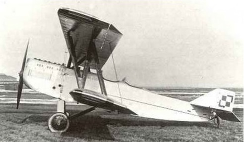
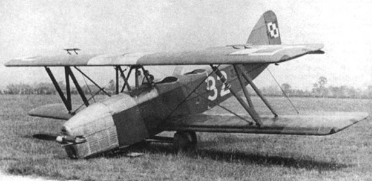
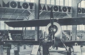
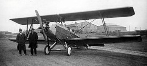
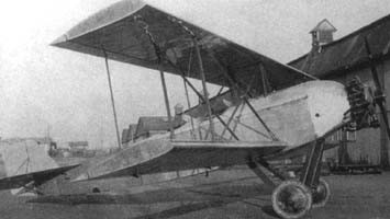
The aircraft was designed by Ryszard Bartel in the Samolot factory in Poznań. It was a development of the Bartel BM-2, which did not advance beyond the prototype stage. The Bartel BM-4 performance was superior to the BM-2, and also to the Hanriot H.28, used by the Poles and licence-built by Samolot.
Wooden construction biplane, conventional in layout. Fuselage rectangular in cross-section, plywood covered (engine section – metal covered). Rectangular two-spar wings, plywood and canvas covered. Crew of two, sitting in tandem in open cockpits, with individual windshields. Cockpits with dual controls, instructor’s at rear. Fixed landing gear, with a rear skid.
The BM-4 prototype was flown on 20 December 1927 in Poznań. It had good handling and stability and was resistant to spinning. A distinguishing feature of all Bartels was an upper wing of a shorter span, because lower and upper wing halves were interchangeable (i.e. the lower wingspan included the width of the fuselage).
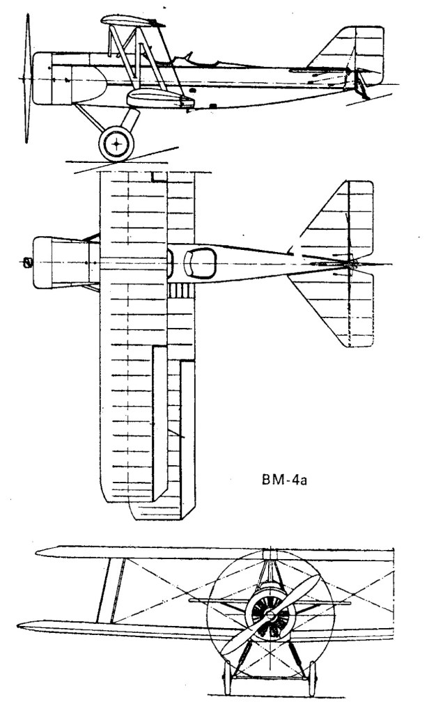
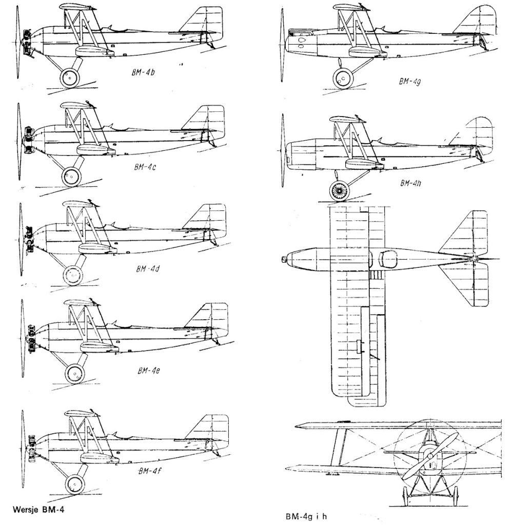
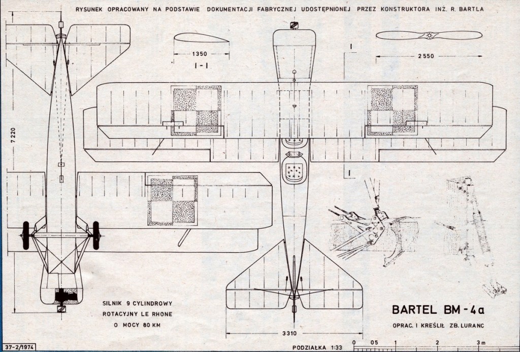
The first prototype was designated BM-4b and was fitted with 90 hp Walter Vega radial engine. The first prototype BM-4b was given to the king of Afghanistan Amanullah Khan during his visit to Poland in 1928. The second prototype, flown on 2 April 1928, was designated BM-4d and fitted with the Polish experimental 85 hp WZ-7 radial engine, then refitted with 80 hp Le Rhône 9C rotary engine and redesignated BM-4a. The BM-4a became a production variant, because the Polish Air Force had a store of Le Rhône engines. 22 aircraft were ordered and built in 1928–1929. This variant had a cowled engine which made it different from all other BM-4s with radial engines.
Next several variants remained experimental. The BM-4c with a 125 hp Lorraine-Dietrich 5Pb radial engine, built as a one-off in 1928, was supposed to be used for long-distance flights to advertise the engines, but was finally used as the factory’s aircraft. Three BM-4a’s were converted to BM-4e of 1930 with the Polish experimental 85 hp Peterlot radial engine, the BM-4f of 1931 with the Polish experimental 120 hp Skoda G-594 Czarny Piotruś radial engine, and the BM-4g of 1931 with 100 hp de Havilland Gipsy I inline engine. The last one competed against the RWD-8 in a search for a standard trainer aircraft, but was not selected. After tests in 1932, all three were converted back with Le Rhône engines.
The second series variant became BM-4h, with 120 hp de Havilland Gipsy III or 120 hp Walter Junior 4 inline engines. Like late BM-4a’s, they had a rounded tailfin and a modified undercarriage. Due to the Samolot factory’s closure in 1930, the BM-4h was developed at the PWS (Podlaska Wytwórnia Samolotów) and built there in 1932 in a series of about 50 aircraft.
BM-4a’s were used in the Polish Air Force from 1929 – in pilots’ school in Bydgoszcz. 6 burnt in September 1929 in the Samolot factory. BM-4h’s were used in the Polish Air Force from 1932, in schools in Bydgoszcz and Dęblin. They only partly replaced Hanriot H.28s and were themselves replaced with the RWD-8. They had military numbers starting with 33.
In 1936 the Polish Air Force handed over their remaining 23 BM-4h’s to civilian aviation – most to regional aero clubs, some to the Ministry of Communication. They received registrations SP-BBP – BBZ and from a range SP-ARB to ARZ. Several survived until the German invasion of Poland in September 1939. Several were used as liaison aircraft during the campaign. None survived the war.
Variants:
BM-4a
Engine: Le Rhône 9C, 80 hp / 60 kW nominal power.
Propeller: Two-blade wooden 2.55 m diameter.
Wingspan: 10.175 m (33 ft 5 in)
Wing area: 25 m2 (270 sq ft)
Length: 7.22 m (23 ft 8 in)
Height: 2.93 m (9 ft 7 in)
Empty weight: 538 kg (1,186 lb)
Gross weight: 359 kg (791 lb)
Fuel tank (fuselage): 89.5 lt
Wing loading: 31.6 kg/m2 (6.5 lb/sq ft)
Power/mass: 0.101 kW/kg (0.0615 hp/lb)
Maximum speed: 125 km/h (78 mph; 67 kn) at sea level
Cruising speed: 110 km/h (68 mph; 59 kn)
Stall speed: 57 km/h (35 mph; 31 kn)
Endurance: 3 hours
Service ceiling: 2,820 m (9,252 ft)
Rate of climb: 1.9 m/s (370 ft/min)
Time to altitude 1,000 m / 3,281 ft: 9 min 42 sec
Crew: 2
BM-4b
Engine: Walter Vega, 90 hp take-off power, 85 hp nominal power.
Propeller: Two-blade wooden 2.55 m diameter.
Fuel tank (fuselage): 89.5 lt
BM-4c
Engine: Lorraine-Dietrich 5Pb, 125 hp take-off power, 110 hp nominal power.
Propeller: Two-blade wooden 2.55 m diameter.
Fuel tank (fuselage): 89.5 lt
BM-4d
Engine: Avia WZ-7, 85 hp take-off power, 80 hp nominal power.
Propeller: Two-blade wooden 2.55 m diameter.
Fuel tank (fuselage): 89.5 lt
BM-4e
Engine: Peterlot, 85 hp take-off power, 80 hp nominal power.
Propeller: Two-blade wooden 2.55 m diameter.
Fuel tank (fuselage): 89.5 lt
BM-4f
Engine: Skoda G-594 Czarny Piotruś, 120 hp take-off power, 100 hp nominal power.
Propeller: Two-blade wooden 2.55 m diameter.
Fuel tank (fuselage): 89.5 lt
BM-4g
Engine: de Havilland Gipsy I, 100 hp take-off power, 90 hp nominal power.
Propeller: Two-blade wooden 2.55 m diameter.
Fuel tank (fuselage): 89.5 lt
BM-4h
Engine: de Havilland Gipsy III, 120 hp nominal power or Walter Junior 4, 120 hp take-off power, 110 hp nominal power.
Propeller: Two-blade wooden 2.55 m diameter.
Fuel tank (fuselage): 89.5 lt
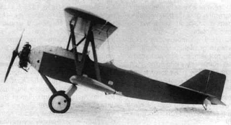
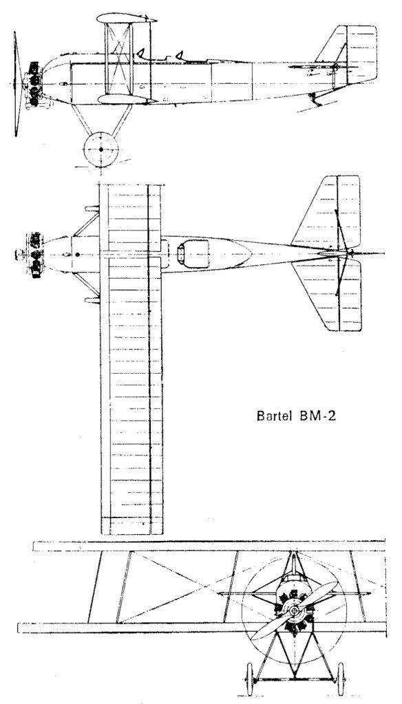
The Bartel BM-2 was designed by Ryszard Bartel, a chief designer of Samolot factory in Poznań. It was the first Polish design of a trainer plane. Initially it was known as Bartel M-2, then BM-2 (M was for designer’s wife Maryla).
A wooden construction biplane, conventional in layout. Fuselage rectangular in cross-section, plywood-covered (engine section – metal covered). Rectangular two-spar wings, plywood- and canvas-covered. Crew of two, sitting in tandem in open cockpits, with individual windshields. Cockpits with twin controls, the instructor seated aft. Fixed landing gear, with a rear skid (main gear with a common axle, sprung with a rubber rope). Radial engine in the fuselage nose, without a cowling.
A feature of the BM-2 and all Bartels was an upper wing of a shorter span, because the lower and upper wing halves were interchangeable (i.e. the lower wingspan included the width of the fuselage). Also Bartel put a stress on standardizing the construction materials used: steel pipes, metal sheet etc, in order to make production and repairs easier. A distinguishing feature of the BM-2 was the upper wing directly over the lower wing – un-staggered wings, while in later Bartel designs, the wings incorporate forward stagger.
The prototype was flown on 7 December 1926 in Poznań. In June 1927 it was shown at the first Aviation Exhibition in Warsaw. It was tested in 1927 and evaluated as quite good, but it was not built in series, because Bartel decided to design an improved aircraft, which resulted in the Bartel BM-4 trainer, which was produced in quantity. After flight testing, the prototype was removed from service.
Engine: 1 × Salmson 9 Ac, 90 kW (120 hp)
Prop: 2 blade, 2.24m diameter
Wingspan: 11.77 m (38 ft 7¼ in)
Wing area: 28.6 m² (308 ft²)
Length: 7.8 m (25 ft 7 in)
Height: 3.08 m (10 ft 1¼in)
Empty weight: 695 kg (1,529 lb)
Loaded weight: 970 kg (2,314 lb)
Useful load: 275 kg (605 lb)
Fuel capacity: 201 lt
Cruise fuel consumption: 34 lt/hr
Maximum speed: 128 km/h (69 knots, 80 mph)
Cruise speed: 100 km/h (54 knots, 62 mph)
Stall speed: 65 km/h (35 knots, 40 mph)
Range: 320 km (173 nm, 199 miles)
Service ceiling: 4,000 m (8,800 ft)
Rate of climb: 2.9 m/s (570 ft/min)
Wing loading: 33.8 kg/m² (7.51 lb/ft²)
Power/mass: 0.093 kW/kg (0.052 hp/lb)
Crew: 2, student and instructor

In 1913, several copies of the Austrian Lohner Pfeilflieger aircraft (later Lohner B.I) were brought to Spain. After reviewing the design of these aircraft from Eduardo Barron (Eduardo Barrón y Ramos de Sotomayor) decided to modify the Pfeilflieger.
As a result, on April 3, 1915, a new lightweight auxiliary aircraft, the Barrón Flecha (arrow), flew into the sky. After successful tests for the Spanish Air Force, six such aircraft were ordered. All of them were built in the workshops of Cuatro Vientos. Several aircraft like the Pfeilflieger were equipped with an Austro-Daimler engine with an output of 80 hp, and the rest received 100-horsepower Mercedes engines.
At the end of 1916, the Hispano Suiza 8A eight-cylinder engine with a power of 140 hp appeared. (103 kW). Eduardo Barron equipped this engine with one Flecha and arranged a demonstration flight for the King of Spain Alfonso XIII.
After receiving royal approval, Barron built 12 aircraft for the Aeronáutica Militar at the Carde and Escoriaza plant in Zaragoza. The military used Flecha until 1919. And Barron based on the Arrow has developed an even more advanced machine – Barron W.
Wingspan: 13.40 m
Length: 8.50 m
Height: 3.00 m
Wing area: 37.50 sq.m
Empty weight: 630 kg
Max weight: 970 kg
Engine: Hispano Suiza 8A, 140 hp
Max speed: 115 kph
Cruise speed: 95 kph
Crew: 2

The 1909 Barnwell canard biplane was designed and built in Scotland by Frank and Harold Barnwell. It was flown only briefly.
Span: 48′
Weight: 1568 lb
