Back to Grumman A-6 Intruder

Many airfoils have “mod” at the end of their designation. Typically, this means that either the camber line has been modified, the leading edge contour has been modified or that the trailing edge thickness has been changed.
Some common airfoil name prefixes and their designers are:
ARA – the Aircraft Research Association, Ltd. in Britain
Clark – Col. Virginius Clark of the NACA
Davis – David Davis, an independent airfoil designer
DESA – Douglas El Segundo Airfoil
DLBA – Douglas Long Beach Airfoil
Do – Dornier
DSMA – Douglas Santa Monica Airfoil
DFVLR – the German Research and Development Establishment for Air and Space Travel
DLR – the German Aerospace Center
Drela – Dr. Mark Drela of MIT
EC – the National Physical Laboratories in Britain
Eiffel – Gustave Eiffel, an early French aeronautical researcher
Eppler – Dr. Richard Eppler of the University of Stuttgart
FX – Dr. F.X. Wortmann of the University of Stuttgart
GU – University of Glasgow in Scotland
Gilchrist – Ian Gilchrist of Analytical Methods, Inc.
Gottingen – the AV Gottingen aerodynamics research center in Germany
Joukowsky – Nicolai Egorovich Joukowsky, an early Russian aeronautical researcher
K – Dr. Yasuzu Naito of Nakajima
LB – Dr. Ichiro Tani of Tokyo University
Liebeck – Dr. Robert Liebeck of McDonnell Douglas, now Boeing
Lissaman – Dr. Peter Lissaman of AeroVironment Inc.
MAC – Airfoils designed at Mitsubishi. During the 1940s, the designer was Tsutomu Fujino.
McWilliams – Rick McWilliams, an independent airfoil designer (broken link: http://www.aircraftdesigns.com/Page1.htm)
Narramore – Jim Narramore of Bell Helicopter Textron
NACA – the US National Advisory Committee for Aeronautics
NASA – the US National Aeronautics and Space Administration
NN – Dr. Hideki Itokawa of Nakajima
NPL – the National Physical Laboratories in Britain
Navy – the US Navy, Philadelphia Navy Yard
Onera – the French National Aerospace Research Establishment
RAE – the Royal Aeronautical Establishment in Britain
RAF – the National Physical Laboratories in Britain
Riblett – Harry Riblett, an independent airfoil designer
Roncz – John Roncz, an independent airfoil designer
Selig – Dr. Michael Selig of the University of Illinois at Urbana-Champaign
Somers – Dan Somers of Airfoils, Inc.
TH – Dr. Tatsuo Hasegawa of Tachikawa
TsAGI – the Russian Central Aerodynamics and Hydrodynamics Institute
USA – the US Army
Viken – Jeff Viken of NASA Langley Research Center
Bert Volk started life as an engineer making cars in 1910.
A year later the first airplane landed in Brighton on the beach, a Bleriot monoplane. Volk became fascinated with aviation and he thought he would have a go.

In 1911, he started making parts for engines, wings, floats, and fabric bodies that would be fitted into planes, and two years later pleasure flights began being launched.
Bert Volk’s elder brother, Herman, invented a collapsible, portable hanger on the edge of the water from where pleasure flights started.
They were all built in bits and taken down to the seafront next to the Banjo Groyne, put together and launched into the sea.”
There was a ramp down into the water and planes were launched into the sea.
Seaplane pleasure flights began in Brighton in 1913
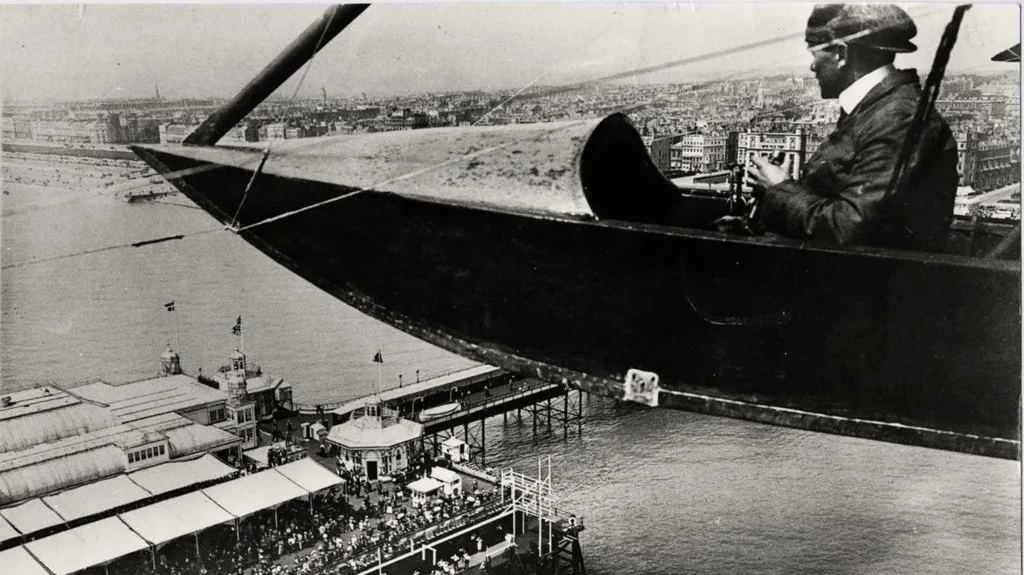
A year after flights started, the outbreak of World War One meant the hanger was requisitioned by the government and the project ended.
Herman Volk went off to manufacture planes for the war effort.
He also contributed to the development of Shoreham Airport – one of the first aerodromes in England.
After the war he took over the running of Volk’s Electric Railway on the seafront.
Bert went off to South Africa where he spent most of the rest of his life.
1964
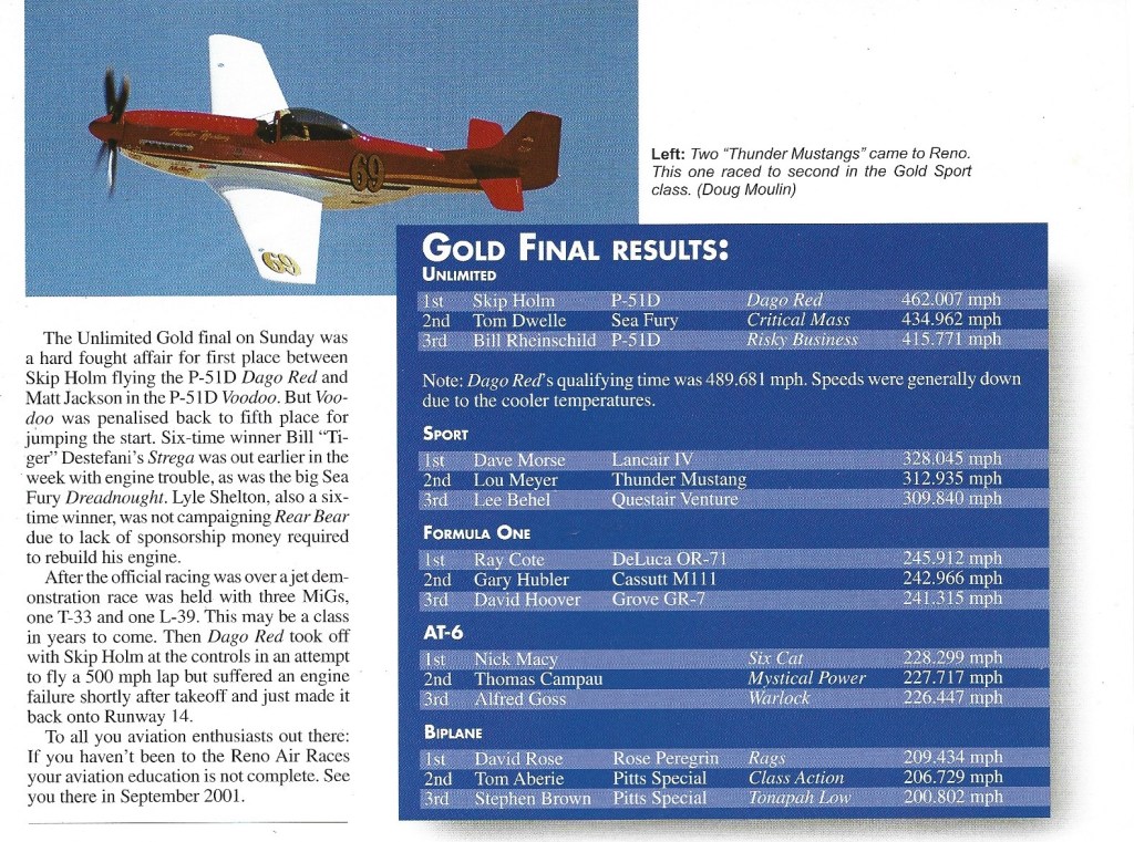
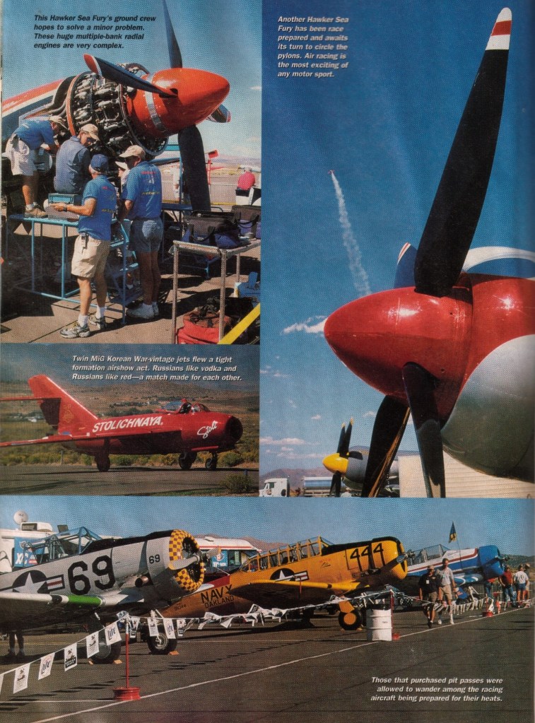
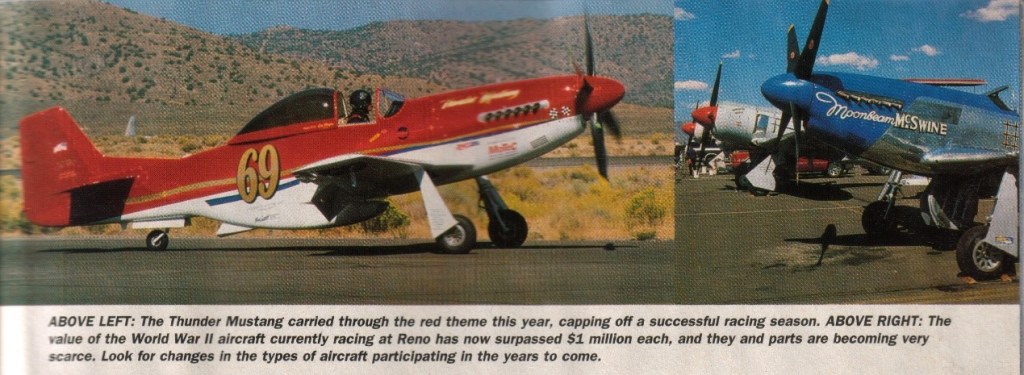
Mira Slovak, Manhattan Beach, California, on 20 September 1964, won the Unlimited championship in his white F8F Bearcat at Reno Sky Ranch. He flew ten laps of the 8.5 mile course in 13 minutes 32 seconds for a 376.84 mph average.
Robert Love of San Jose, California, finished second in a white Mustang, the Bardahl Special. Clay Lacy, Canoga Park, California, was third, also in a Mustang.
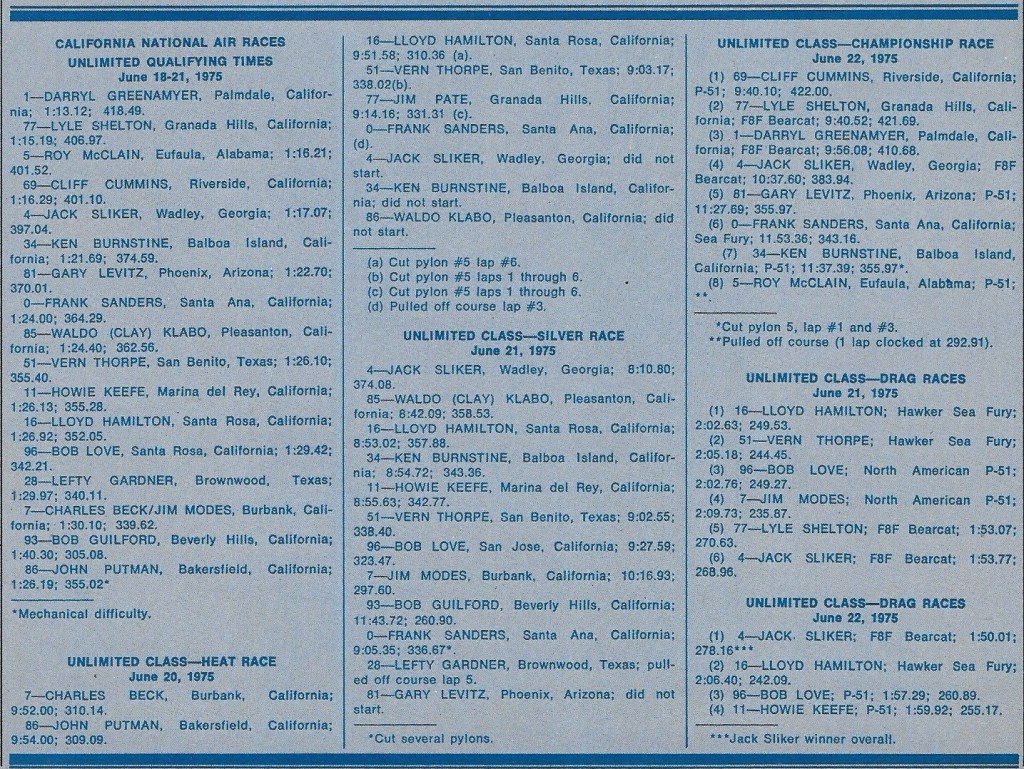
1975
2000










2007


The Turbo-Union RB199 is a turbofan jet engine designed and built in the early 1970s by Turbo-Union, a joint venture between Rolls-Royce, MTU and Aeritalia.
The RB199 originated with a requirement, in 1969, to power a new European multirole combat aircraft (MRCA) called the Panavia MRCA. The engine requirements to meet the Panavia MRCA specification were significant advances over current engines in thrust-to-weight ratio, fuel consumption and size. The final selection of the engine for the MRCA was made between a new European collaboration, Turbo Union, with the RB199, and Pratt & Whitney who proposed the JTF16. The Panavia MRCA would later be called the Panavia Tornado.
Advanced engine studies at Bristol Siddeley had already been done to support the BAC/Dassault AFVG and were based on the Pegasus two-spool arrangement. At Rolls-Royce, where the three-shaft RB211 engine was in development, three shafts were considered better. Rolls-Royce took over Bristol Siddeley in 1967 so the configuration for the RB199 was decided, a three-shaft engine, but fundamentally to Bristol’s design and Bristol’s higher technology.
The overall design concept for the international collaborative program, three shafts was decided by Rolls-Royce. The bypass ratio was chosen for long-range, with low fuel consumption, particularly when throttled back. The selected BPR also gave a higher reheat boost than with smaller values used on similar engines. The design of the individual modules was shared between Rolls-Royce, MTU and Fiat according to their existing expertise. Rolls-Royce designed the fan using scaled-down Pegasus knowledge, the combustor, the high pressure (HP) turbine and the reheat. The reheat used cold air combustion techniques, described by Arthur Sotheran and which were derived from their experience with ramjets and plenum chamber burning (PCB) in Pegasus front nozzles. Fiat had built turbines for the Viper so designed the low pressure (LP) turbine as well as the final nozzle. MTU designed the intermediate pressure(IP) and high pressure (HP) compressors, the IP turbine, and the thrust reverser.
A three-spool arrangement reduces the pressure ratio on each compressor so no variable stators were needed. To meet the short afterburner requirement an arrangement known as mix-then-burn, as used in current engines, was not possible because it was too long and heavy. The RB199 used a much shorter arrangement known as mix/burn.
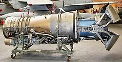
The RB199 first ran on 27 September 1971 at Patchway, UK. It was flight-tested using an Avro Vulcan with the engine installed in a nacelle that was representative of the Tornado aircraft. The Vulcan first flew with the RB199 in 1972.
Service flying with the Royal Air Force, German Navy and German and Italian Air Forces in the European environment showed normal failure mechanisms for turbine blades, thermal fatigue, creep and high cycle fatigue (HCF) so development started on replacing the initial production equiaxed blades with single-crystal ones which last longer at high temperatures.
Sand ingestion tests had been done and passed as part of the qualification for service introduction but operating in desert conditions with the Royal Saudi Air Force produced new problems. Frequent flying in air carrying different sizes of sand particles caused deposits on the HP turbine blades from sand passing through the combustor. In addition, sand carried with the cooling air through the blades blocked the cooling holes. Single crystal blades were being introduced to improve the life of the blades for the European operating conditions and revised cooling hole arrangements were introduced at the same time to reduce the detrimental effect of sand on blade cooling. With incorporation of these blade processing and cooling changes “Desert Storm Tornado aircraft flew some of the most arduous missions of any Allied aircraft with reliability no worse than peacetime and no engines were rejected for HP Turbine blade defects.”
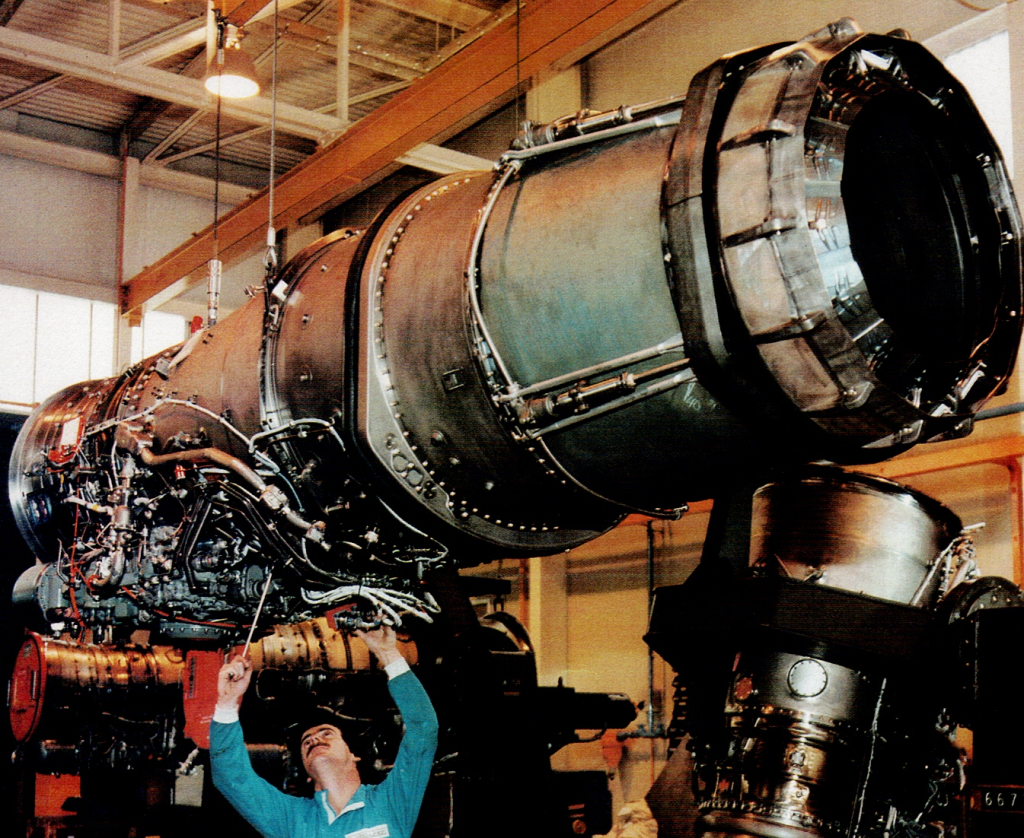
Looking back on the RB199 program in 2002 Chief Engineer for the RB199, Dr. Gordon Lewis, concluded “The final production standard provided satisfactory reliability and performance.
Variants and applications
RB199 Mk 101
Initial variant powered first Tornado IDS deliveries, with a 38.7kN (8700lbf) dry thrust, 66.01kN (14840lbf) with afterburner.
RB199 Mk 103
Powering Tornado IDS strike versions, with a thrust rating of 40.5 kN (dry) 71.2 kN (reheat)
RB199 Mk 104
Powering the Tornado F3 Air Defence Variant, with a thrust rating of 40.5 kN (dry) 73 kN (reheat)
RB 199 Mk104D
Derivative used on the BAe EAP.
RB199 Mk 105
Powering Tornado ECR versions and applicable to IDS, with a thrust rating of 42.5 kN (dry) 74.3 kN (reheat)
RB199-122
A derivative of the Mk104 (originally designated Mk 104E[13]), powering the first two prototypes of the Eurofighter Typhoon (DA1 and DA2) until the initial versions of the Eurojet EJ200 were available.
Specifications (RB199-104)
Type: Turbofan
Length: 3,600 mm (142 in)
Diameter: 720 mm (28.3 in)
Dry weight: 976 kg (2,151 lb)
Compressor: 3-stage LP, 3-stage IP, 6-stage HP
Turbine: Single-crystal HP, single-crystal IP, 2-stage LP
Maximum thrust: 40 kN (9,100 lbf) dry, 73 kN (16,400 lbf) wet
Turbine inlet temperature: ~1,600 K
Thrust-to-weight ratio: 7.6 (with reheat)

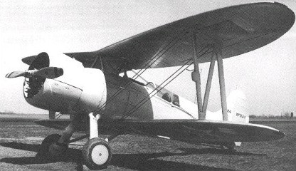
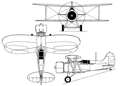
Designed by the US Navy Bureau of Aeronautics, the XF3J-1 was turned over to the Berliner-Joyce Corporation for development and construction. Ordered on 30 June 1932, this experimental single-seat shipboard fighter was completed in January 1934.
Of all-metal construction with a semi-monocoque fuselage and fabric-covered wings, the XF3J-1 was powered by a 625hp Wright XR-1510-26 radial. Armament was two 7.62mm synchronised machine guns, and provision was made for two 50kg bombs beneath the wings.
Although offering a good performance, the XF3J-1 was surpassed by the Grumman XF2F-1, and no further development was undertaken.
Engine: 625hp Wright XR-1510-26 radial
Empty weight: 1233 kg/2718 lb
Wingspan: 8.84 m/29 ft 0 in
Length: 6.98 m/23 ft 11 in
Height: 3.28 m/11 ft 9 in
Wing area: 22.26 sq.m/239.60 sq ft
Max. speed: 336 km/h/209 mph
Range: 1157 km/719 miles
Armament: two 7.62mm synchronised machine guns, two 50kg bombs