Bob Bailey had worked for Advanced Aviation and the development of the Buccaneer flying boat ultralight. He later developed the Moyes Dragonfly and Tempest ultralight sailplane.
LSA/UL
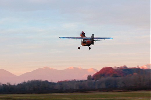
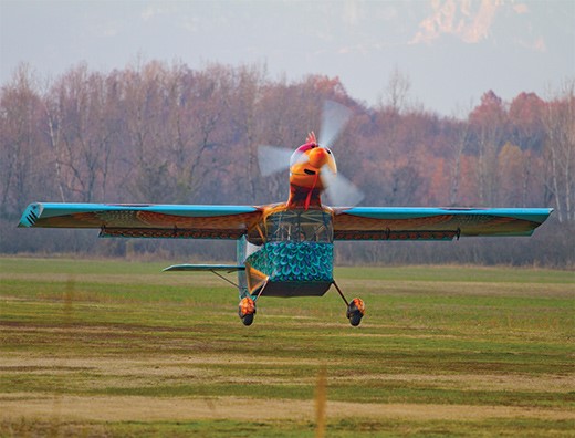
Baggio Rooster
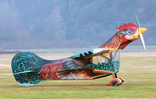
At Nervesa della Battaglia, near Treviso in northeastern Italy, aircraft designer and homebuilt aircraft enthusiast Ottone Baggio conceived the idea of building a flying machine modelled on the world’s best known flightless bird: the rooster.
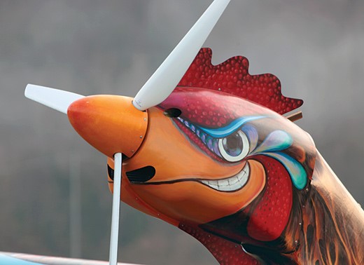
The engine nacelle (the rooster’s head) would be mounted well ahead and above the wing leading edge. The design does not utilize fuselage and wing components from any other kit aircraft, and is 100% original. The wings are of a conventional, lightweight wood structure with a forward box spar that runs through the roof of the cockpit, plus trailing edge spar; there are no wingstruts, and the wings have a 1 degree dihedral. They are covered in extremely thin-gauge aluminum with a total span of 29 feet, and, unusually, the “bird” has 66%-span flaperons, but these are on the inboard sections of the wings. The wingtips are square and flattish, slightly angled inward with wingtip strobes, and the ailerons are cable operated.
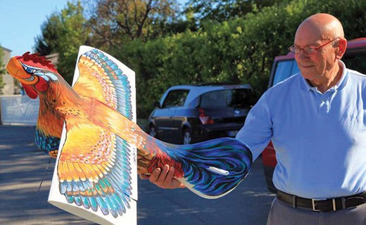
The Rooster took about three years to conceive, design and build. Ottone started with model airplanes, first a “chuck” (hand-launched) glider and then a radio-controlled version. Proving that in small scale such a design would fly, he developed a prototype that would be partially like a conventional, three-axis-controlled small airplane, but would have the world’s most exotic color scheme—plus the head of a rooster.
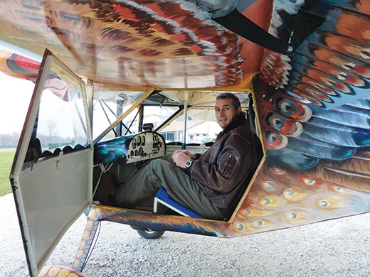
The fuselage is steel tube with gussets covered by fabric, though areas of the forward fuselage are covered in thin-gauge aluminium. The rooster’s head, which is the engine compartment, is a molded composite cowling around a tubular-steel engine bearer. The cockpit resembles that of a 1930s airship gondola with a rounded, acrylic screen and a basic panel. The rudder is linked to the tailwheel, and there are caliper brakes on the mainwheels operated from a hand-actuated brake lever on the panel. Because of the engine’s high thrust line, Baggio has designed a huge tail and rudder relative to the meager 19-foot total length of the rooster, and he even fitted a dorsal “rudder” in which the steerable tailwheel is shrouded.
It has an empty weight of 500 pounds and is powered by a 100-horsepower Rotax 912 engine. The paint job took many months of detailed work with an amazing palette of colors.

The Rooster, registered in the Italian ultralight sequence as I-9923, was actually completed earlier but suffered some fast-taxi mishaps. In December 2011, the test pilot, fellow homebuilder Daniele Beltrome carried out many fast taxi trials and a few tentative hops. “The Rooster is a difficult aircraft to fly,” he reported (no kidding!) and suggested a few adjustments to its elevators and control-wire cable tensions. The first proper flight, lasting about 10 minutes, had the Rooster leaving the airfield, completing a slow 180 turn and then returning to the airfield.
Unfortunately, Beltrome further reported, “The Rooster is unstable in roll and has a tendency to go into the first stages of a spin when you start to turn, if it isn’t noticed and checked.” He put in one stage of the flaperons to try to solve this problem. This is why the first flight turn was a very gentle affair with little more than 5 of bank and often less, with a very obvious and “twitchy” pitch.
The Rooster is its control system works in reverse to a normal three-axis-control aircraft. The control column comes down from the roof of the cockpit, and the control inputs are exactly the opposite to what one learns in normal piloting skills, so you pull back on the stick to go down and vice versa. This is the reason for some of the accidents during early taxi tests. It is apparently more like flying a delta-wing hang glider.
More test flying was planned and the builder may extend the flaperons to full span to help improve roll control. But like the bird of its inspiration, the Rooster is unlikely to fly that much and achieve widespread acceptance among homebuilders and pilots. It is more the product of a dream becoming reality. However, as an aviation spectacle, the sight of the Rooster flying over the Nervesa Valley has gotten everyone talking aviation and flight, though it may also have stirred considerable unrest and disruption to egg production in local hen houses.
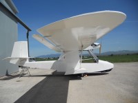
Bagalini Baganfibio
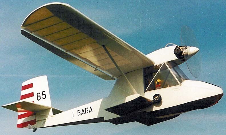
The Bagalini Baganfibio (from “Bagalini” and “Amphibian”) is an Italian homebuilt flying boat that was designed by Marino Bagalini. The two-seat tandem amphibious aircraft was supplied in the form of plans for amateur construction.
The Baganfibio features a strut-braced high-wing, a two-seats-in-tandem enclosed cockpit, retractable conventional landing gear and a single engine in tractor configuration mounted above the wing.
The aircraft is of all-wooden construction, with its wings covered in doped aircraft fabric. Its 10.7 m (35.1 ft) span wing employs an RSG 36 airfoil and has Junkers ailerons. The aircraft does not use tip floats, but instead relies on sponsons for balance in the water. The acceptable power range is 40 to 50 hp (30 to 37 kW).
Full fuel is 26 litres (5.7 imp gal; 6.9 US gal) and the payload is 151 kg (333 lb).
The manufacturer estimates the construction time from the supplied kit as 700 hours.
Plans were available in 1998.
Engine: Rotax 503, 50 hp / 37 kW
Wingspan: 35 ft 0 in / 10.67 m
Wing area: 167 sq. ft / 15.5 sq.m
Airfoil: RSG 36
Length: 22 ft 0 in / 6.71 m
Empty weight: 385 lb / 175 kg
MTOW: 759 lb / 344 kg
Fuel capacity: 26 litres (5.7 imp gal; 6.9 US gal)
Wing loading: 22 kg/sq.m / 4.5 lb/sq ft
ROC 600 fpm / 3.0 m/s
Cruise: 43 mph / 69 km/h / 37 kn
Max speed: 62 mph / 100 km/h / 54 kn
Range: 130 mi / 210 km / 110 nmi
Stall: 28 mi / 45 km/h / 24 kn
Seats: 2
Badcock Kitty Fox
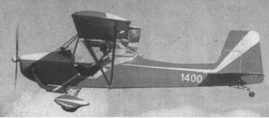
Keith Bennett of Devonport, Tasmania, Australia, asked Owen Badcock about designing him a plane. Owen Badcock proceeded to draw up some plans and then built a one-quarter scale radio¬controlled model complete with folding wings. This performed completely as planned with no need for modifications. Keith started building in June 1992.
All stress-bearing metal parts are chrome molydenum steel tube which after welding (T.I.G.) has been sand blasted, oil filled, primed and then painted with two-pack white. The wing ribs are Epi glued Canadian Spruce with 6m l2ply noses and tails. All moving parts are nylon bushed. An early problem with tail-wheel shimmy was solved by Keith who turned up a wheel from solid aluminium to fit a standard ball-bearing. A solid rubber tyre was vertical stabilizer and the leading edges of the wings snug up to rubber blocks on the roof and sides of the trailer as the plane settles ‘home’ upon loading. Starting of the 503 DCDI engine is facilitated by use of a G.A. type fuel primer. The wheel brakes are operated by twin levers conveniently situated forward of the throttle lever on the left side of the cockpit. This makes for very easy taxing. For parking a spring loaded lever can be rotated to hold both levers on. This unlocks automatically when the brake levers are activated.
Wing folding is affected by first half withdrawing a pin on the leading-edge spar at the root of each wing. This unlocks a safety-pin which is moved ‘on’ by the last part of the pins travel when it presses down on a nylon wedge on the forward end of a rod. The aft end of the rod carries the safety pin which prevents the spring loaded flaperon disengaging mechanism separating in flight in the event of spring failure. The flaperon as are then disengaged for wing folding and held up by a small piece of shock-cord which retracts into the wing when not in use. The leading edge spar pin can then be lifted right out and the wings swing back and locked on to the tail. The whole operation takes two minutes.
Backstrom Flying Plank EPB-1 / WPB-1 Powered Plank
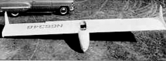
The Flying Plank was developed in 1954 by Al Backstrom, assisted by Phil Easley and Jack Powell. The prototype EPB-1 was used for drag reduction tests at the Mississippi State College, using a modified Abrial reflex airfoil.
Plans for the -1A development were sold and a number built, most with twin wingtip rudders, but some were completed with a central fin and rudder at the end of a lengthened fuselage (EPB1-C) to improve performance and control. Span have varied up to 9.30 m / 30.5 ft. A self-launching model was developed later.
Except for the fiberglass nose cap for the fuselage, standard wood structure was used throughout, and construction time for an experience woodworker was in the neighborhood of 600 hours. More than 150 sets of plans were sold.

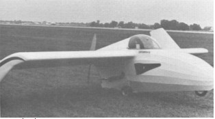
Construction of the powered Plank was begun in 1972, most of the work being done by Van White, a director of the EAA (Experimental Aircraft Association). It was intended originally to fit a Sachs Wanzel or OMC snowmobile Wankel engine, but as neither became available, a fan-cooled single-ignition Kiekhaefer Aeromarine 440 was installed, driving a two-bladed pusher propeller via belts.
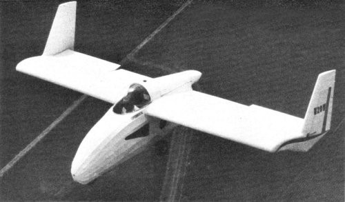
The original tandem-wheel/outrigger undercarriage was replaced by a more robust tricycle unit in 1976.
An improved version, the “Super Plank”, was under development in 1973. At least two of them were built, including N20WB, by Larry Linville and Dennis Harmon. Backstrom also built a motor glider light aircraft called WPB-1 Powered Plank in early 1970s.
The Backstrom WPB-1 is on display at the Airpower Museum in Blakesburg, IA. And the Vintage Sailplane Association has plans.
EPB-1A
Wing Span: 7.62m / 25ft
Wing Area: 9.29sq.m / 100sq.ft
Empty Weight: 68kg / 150lb
Payload: 91kg / 200lb
Gross Weight: 159kg / 350lb
Wing Load: 17.11kg/sq.m / 3.5lb/sq.ft
L/DMax: 20@ 97 kph / 52 kt / 60 mph
Seats: 1
MinSink: 1.07 m/s / 3.5 fps / 1.88 kt
Aspect ratio: 6.25
Airfoil: Abrial 15%
Structure: wood / fabric
WPB-1 N20WB
1975
Engine: 40hp Kiekhafer Aeromarine 440
Wingspan: 21’0″
Length: 11’0″
Useful load: 220 lb
Max speed: 106 mph
Stall: 55 mph
Seats: 1
Back Forty Developments Tundra
A tandem two-seat microlight
Back Forty Developments Ltd
Canada
Markets kits for the Tundra tandem two-seat microlight.
Back Bone Spirit / Revolution Spirit
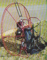
The engine has a centrifugal clutch. There is an auxiliary strap on the harness for easy handling without much effort on the brakes.
Spirit 113
Engine: Vittorazi, 14.5 hp
Reduction: 1-3
Prop diameter: 113 cm
Empty weight: 17 kg
Fuel capacity: 7 lt
Price (1998): 23,000F
Spirit 113A
Engine: Vittorazi, 17
Reduction: 1-3
Prop diameter: 113 cm
Empty weight: 16 kg
Fuel capacity: 7 lt
Price (1998): 22,600F
Spirit 125
Engine: Vittorazi, 14.5 hp
Reduction: 1-4
Prop diameter: 125 cm
Empty weight: 18 kg
Fuel capacity: 7.5 lt
Price (1998): 23500F
Spirit 125A
Engine: Vittorazi, 17 hp
Reduction: 1-4
Prop diameter: 125 cm
Empty weight: 17 kg
Fuel capacity: 7 lt
Price (1998): 22,900F
BAaer BA-5 Gur
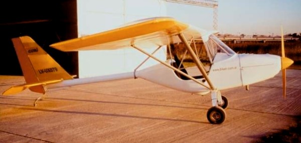
The design goal for the Gurí was for a versatile ultralight and also an airplane kit that is easy to build. The Gurí design uses metalic and composites where it made the most sense from an engineering and a construction standpoint. The Gurí constant-chord wings are aluminum and fabric, with slotted ailerons and flaps.
For the compound curves of the cockpit, fiberglass composites are used. Fiberglass fabrics and epoxy-vinylester resin factory molding cockpit, landing gear and several parts insures a smooth finish and a simple assembly project. Rear fuselage is a 6 inch diameter aluminum tail boom with aluminum tube and fabric tail surfaces.
The main goal of the kit is the assembly of parts supplied, covering the flight surfaces, install system and engine, ulphostery and painting. It does not include a engine, prop, paint and instruments.
Optional equipment includes wheel pants, instruments, floats, and ballistic chute. This aircraft can have 50 HP to 80 HP engine. Price 2009: 18000 USD
BA-5 Gurí
Engine: Rotax 503 50 HP
Cruise speed @ 75%: 110 km/h (70 mph)
Stall speed: 55 km/h (35 mph)
Rate of Climb: 3 m/s (600 ft/m)
Never exceded speed (VNE): 190 km/h (120 mph)
Range: 500 km.(313 m.)
Takeoff Distance: 150 m.(500 ft.)
Landing Distance: 150 m.(500 ft.)
Glide ratio: 12:1
G Loading: +6 -4gs
Fuel Consumption: 15 lts/hr
Fuel capacity: 70 lts.
Span: 10 m.(33 ft.)
Length: 6 m.(20 ft.)
Wing area: 14 sq.m (150 sq.ft)
Chord: 1.4 m.(55 in)
Empty weight: 225 kg.(495 lb.)
Gross weight: 450 kg.(1000 lb.)
Cockpit width: 1.05 m.(42 in)
Baggage capacity: 15 kg.(33 lb.)
Seats: 2
BA-5 Gurí
Engine: HKS 700E 60HP
Cruise speed @ 75%: 120 km/h (75 mph)
Stall speed: 55 km/h (35 mph)
Rate of Climb: 3.5 m/s (700 ft/m)
Never exceded speed (VNE): 190 km/h (120 mph)
Range: 840 km.(525 m.)
Takeoff Distance: 150 m.(500 ft.)
Landing Distance: 150 m.(500 ft.)
Glide ratio: 12:1
G Loading: +6 -4gs
Fuel Consumption: 10 lts/hora
Fuel capacity: 70 lts.
Span: 10 m.(33 ft.)
Length: 6 m.(20 ft.)
Wing area: 14 sq.m (150 sq.ft)
Chord: 1.4 m.(55 in)
Empty weight: 225 kg.(495 lb.)
Gross weight: 450 kg.(1000 lb.)
Cockpit width: 1.05 m.(42 in)
Baggage capacity: 15 kg.(33 lb.)
Seats: 2
BA-5 Gurí
Engine: Rotax 582 64HP
Cruise speed @ 75%: 130 km/h (80 mph)
Stall speed: 55 km/h (35 mph)
Rate of Climb: 4 m/s (800 ft/m)
Never exceded speed (VNE): 190 km/h (120 mph)
Range: 500 km.(313 m.)
Takeoff Distance: 100 m.(330 ft.)
Landing Distance: 150 m.(500 ft.)
Glide ratio: 12:1
G Loading: -4gs +6
Fuel Consumption: 18 lts/hr
Fuel capacity: 70 lts.
Stall: 32 kt / 37 mph / 60 kmh
Cruise: 70 kt / 81 mph / 130 kmh
VNE: 103 kt / 118 mph / 190 kmh
Empty Weight: 230 kg / 507 lbs
MTOW Weight: 450 kg / 992 lbs
Climb Ratio: 800 ft/min / 4 m/s
Glide Ratio: 10
Span: 10 m.(33 ft.)
Length: 6 m.(20 ft.)
Wing area: 14 sq.m (150 sq.ft)
Chord: 1.4 m.(55 in)
Empty weight: 225 kg.(495 lb.)
Gross weight: 450 kg.(1000 lb.)
Cockpit width: 1.05 m.(42 in)
Baggage capacity: 15 kg.(33 lb.)
Seats: 2
BA-5 Gurí
Engine: Rotax 912 80 HP
Cruise speed @ 75%: 150 km/h (90 mph)
Stall speed: 60 km/h (38 mph)
Rate of Climb: 5m/s (1000 ft/m)
Never exceded speed (VNE): 190 km/h (120 mph)
Range: 800 km.(500 m.)
Takeoff Distance: 80 m.(260 ft.)
Landing Distance: 150 m.(500 ft.)
Glide ratio: 12:1
G Loading: +6 -4gs
Fuel Consumption: 12 lts/hr
Fuel capacity: 70 lts.
Span: 10 m (33 ft.)
Length: 6 m (20 ft.)
Wing area: 14 sq.m (150 sq.ft)
Chord: 1.4 m.(55 in)
Empty weight: 225 kg.(495 lb.)
Gross weight: 450 kg.(1000 lb.)
Cockpit width: 1.05 m.(42 in)
Baggage capacity: 15 kg.(33 lb.)
Seats: 2
Aydlett A-1
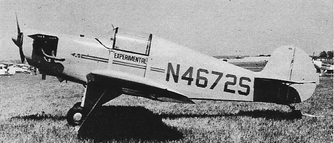
Donald E Aydlett began construction of the sole A-1 in 1963, flying it on 6 July 1965. It was a low wing monoplane of mixed wood and steel construction. The wing was a fabric covered wood structure, with streamlined lift struts from the upper fuselage longerons. The fuselage and tail unit were steel, again fabric covered, and the tail unit was wire braced. The tailplane was on top of the fuselage; the rounded fin carried a generous, unbalanced rudder. The cockpit, over the wing, was enclosed by a canopy which merged at the rear with the raised fuselage decking. Power came from a 125 hp (93 kW) flat four Lycoming O-290-G, mounted with cylinder heads and exhaust pipes exposed. The A-1 had a fixed, conventional undercarriage, with mainwheels mounted on faired V-struts and a tailwheel.
Only one [N4672S, C/N 1001] was ever built.
Engine: 1 × Lycoming O-290-G, 125 hp (93 kW)
Propellers: 2-bladed fixed pitch
Wingspan: 22 ft 3 in (6.78 m)
Length: 17 ft 0 in (5.18 m)
Height: 6 ft 0 in (1.83 m)
Empty weight: 690 lb (313 kg)
Max takeoff weight: 1,200 lb (544 kg)
Maximum speed: 185 mph (298 km/h; 161 kn)
Cruise speed: 115 mph (100 kn; 185 km/h)
Service ceiling: 15,000 ft (4,572 m)
Rate of climb at sea level: 1,000 ft/min (5.1 m/s)
Seats: 1
