Abrial, George

Georges Abrial was born in 1898; in the year 1909 he started to build scale model gliders and eventually built more than 250. After graduating from the St Cyr Aeronautical Institute he became an aerodynamicist for the Levasseur firm.

Abrial stopped designing new aircraft after 1932, being more attracted by instructorship and educational methods and played an important role in the development of soaring in France during the thirties. After the war he was still very active in promoting soaring not only in France, but also in French Africa.

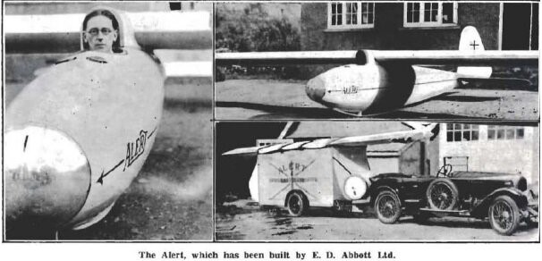
Abbott Farnham / Alert

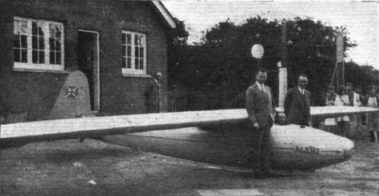
The Abbott Farnham sailplane or Alert (as it was marked on nose) was designed by T. C. Letcher and built in 1930 by E.D. Abbot company.

It features a three-piece cantilever wing with two spars. The undercarriage was a main skid plus tail skid. No airbrakes or flaps were fitted.

It was owned by L.H. Ellis and Russell Taylor.

The first flight was in August 1930 and it took part in the 1930 German National Competitions.

Only the one was built.

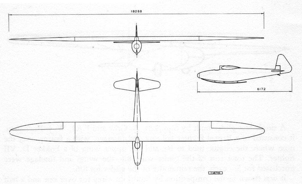
Wingspan: 18.29 m / 60 ft 0 in
Length: 6.17 m / 20 ft 3 in
Wing area: 20.81 s.m / 224 sq.ft
Aspect ratio: 16
Empty weight: 148.78 kg / 328 lb
Max L/D: 22

Abbott-Baynes Scud / Carden-Bayne Auxiliary

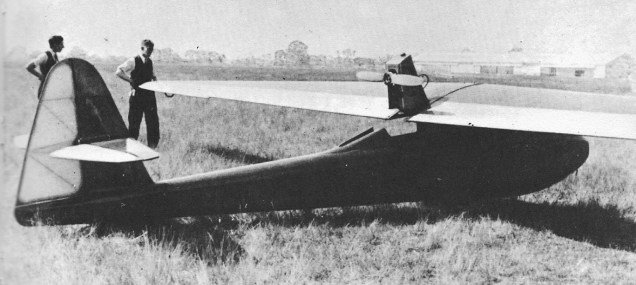
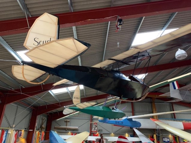
E.D.Abbott, Farnham, produced Mignet Fleas and Baynes Scud during 1935-36. Of conventional construction, the prototype was built by Brant Aircraft Ltd, Waddon Aircraft Factory, Croydon, Surrey. The prototype featured a wire trailing edges to the wings and empennage (fluted). The prototype first flew on 11 January 1931 at Totternhoe, Beds.

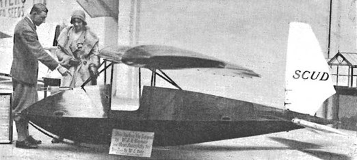
Production Scud I were built by Abbott-Baynes Sailplanes at Farnham, price in 1931 at £95 ex-works. No airbrakes or flaps were fitted. Undercarriage was a main skid only.

The Scud 2 designed by L.E. Baynes was a development of the Scud 1. The prototype first flew at Askam-in-Furness on 27 August 1932. With main skid undercarriage and a tail bumper, no airbrakes or flaps were fitted. They were priced at £150 ex-works in 1932.

In 1935, piloted by Mungo Buxton, a Sud 2 held the British height record of 8750 ft / 2666 m.

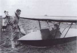
Scud 2 – L.E. Baynes with G. Mungo Buxton in cockpit before 29 September height record at Sutton Bank

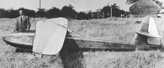
Baynes’ Scud 3 was designed specifically to include such a launching aid but was also capable of high-performance engineless flight. Without an engine it was known as the Abbott-Baynes Scud 3; with the engine, as the Carden-Baynes Auxiliary. Since the engine could be removed or retrofitted the nomenclature sometimes became confused. The Auxiliary is historically significant as the first sailplane with a retractable engine and propeller CG Grey, respected editor of The Aeroplane, wrote after the first flight of the Scud 3, piloted by Dr Dewsbery “Dewsbery now holds the certainly unique position of being the first aviator to retract his motor and airscrew while flying.”

The Scud 3 was an advanced sailplane in its time, all wood and with a long-span wing with heavy taper on the leading edge. The airfoil section was designed by Baynes and varied from the wing root outwards. At the centre it had a flat undersurface, making the wing thick and easy to strengthen as well as reducing wing root interference drag. Outwards, as thickness, chord and incidence reduced, the lower surface became increasingly concave, producing reflex camber. These features were intended to ensure that the stall started at the centre of the wing rather than at its tip. The ailerons were of the differential type. The wings were readily demountable for transport.

Carden-Bayne Auxiliary retracted

The fuselage was flat sided and plywood covered apart from near the nose; upper and lower surfaces were curved and again ply covered. The rounded nose was built up with a double layer of narrow spruce strips placed diagonally. The single cockpit was well ahead of the wings and their mounting pylon had a fairing which extended aft of the trailing edge and contained the engine. At the rear there was a tall fin with an unbalanced rudder. The tailplane was mounted about one third of the way up the fin, carrying split elevators; like the wings it could be removed for transport. The undercarriage was just a single wheel mounted partly inside the fuselage.

The unique feature of the Auxiliary was the powerplant and its mounting. Carden had selected a 250 cc single-cylinder, air-cooled two-stroke Villiers motorcycle engine. He encouraged Villiers to persuade this engine to run inverted, in order to put the propeller line to the top of the mounting and thus minimise air resistance. This proved satisfactory, and many hours of testing with the cowling in place and at full throttle showed there were no overheating problems. A small fuel tank was fixed above the crankcase, at the top of the engine. Carden also designed the engine mounting that enabled the engine and its propeller to be swung out of its housing and into action. The engine was hung to the top of the pylon bulkhead, just ahead of the trailing edge, on a diagonally cross-braced pair of tubes from the hinge to the crankcase and with V-tubes to the cylinder head.

In use the engine and propeller were vertical, the latter having a small diameter to clear the lips of the open top of the fuselage. The engine was held in position by a diagonal longitudinal member attached to a nut on a screw thread which could be rotated with a crank in the cockpit. As the lower end of this member moved forward, the engine rotated into the horizontal position, its fairing closing the fuselage opening. The propeller was indexed to stop in a vertical position and its lower tip moved forward on retraction into a slot in the bulkhead, whilst the other blade pressed on a lever that caused hinged fairing doors, previously held open with springs, to close over it. With the engine retracted, the rear of the pylon was as smoothly faired as on any conventional sailplane.

One other unusual and possibly unique feature of the Auxiliary was that it had a secondary throttle on the port wing tip, so that the pilot could easily taxi the aircraft whilst supporting the wing.

The Scud 3 first flew as an unpowered aircraft in May 1935, and took off under its own power on 8 August that year. It got airborne in 450 ft (140 m) climbing to 2,000 ft (610m) in 15 minutes before Dr Dewsbery retracted the engine and flew it as a sailplane. This first aircraft was still fitted with its engine in 1949, when it was registered as G-ALJR, but in 2010 was flying as an unpowered sailplane. Photographs from the 1930s and ’40s suggest that at some point the closing mechanism of the rear fairing was altered and a fixed slot provided for the propeller. A second Scud 3 was built in 1935 but not fitted with an engine until 1949, when a more powerful 350 cc Villiers was installed until late in 1951. It is on display at the Gliding Heritage Centre.

Scud I, II and III in a line

Gallery

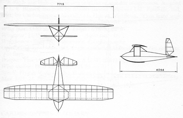
Scud I
Wingspan: 7.72 m / 5 ft 3.76 in
Length: 4.06 m / 13 ft 4 in
Wing area: 7.90 sq.m / 85 sq.ft
Aspect ratio: 7.5
Wing section: Gottingen 535 mod.
Empty weight: 46.72 kg / 103 lb
AUW: 114.76 kg / 253 lb
Wing loading: 14.54 kg/sq.m / 2.98 lb/sq/ft
Max L/D: 15
Min sink: 0.98 m/sec at 48-56 kph / 3.23 ft/sec at 30-35 mph

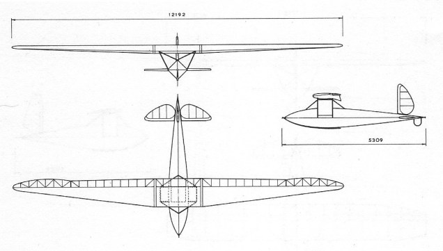
Scud 2
Wing span: 12.19 m / 40 ft 0 in
Wing area: 9.29 sq.m / 100 sq.ft
Aspect ratio: 18
Wing section: Gottingen 652
Length: 5.31 m / 17 ft 5 in
Empty weight: 68.04 kg / 150 lb
AUW: 145.15 kg / 320 lb
Wing loading: 15.63 kg/sq.m / 3.2 lb/sq.ft
Max L/D: 22
Min sink: 0.67 m/sec / 2.2 ft/sec

Scud 3
Wingspan: 45 ft 6 in (13.87 m)
Wing area: 120 sq ft (11 m2)
Aspect ratio: 16
Airfoil: Special Baynes section
Length: 22 ft 6 in (6.86 m)
Height: 4 ft 0 in (1.22 m)
Empty weight: 117.94 kg (260 lb)
Gross weight: 226.8 kg (500 lb)
Maximum speed: 40 mph (65 km/h, 35 kn)
Cruise speed: 35 mph (56 km/h, 30 kn)
Stall speed: 25 mph (40 km/h, 22 kn)
Maximum glide ratio: 1:22
Rate of sink: 132 ft/min (0.67 m/s)
Lift-to-drag: 24:1
Wing loading: 18.31 kg/m2 (3.75 lb/sqft)
Crew: 1

Scud 3
Wingspan: 48 ft 6 in
Length: 19 ft
Wing area: 175 sq.ft
Aspect ratio: 13.2
Empty weight: 300 lb
Gross weight: 470 b
Min sink: 2.8 ft/sec
Glide ratio: 18-1

Carden-Bayne Auxiliary
Powerplant: 1 × Villiers 250 cc, 9 hp (6.7 kW) at 3,500 rpm
Wingspan: 45 ft 6 in (13.87 m)
Wing area: 120 sq ft (11 m2)
Aspect ratio: 16
Airfoil: Special Baynes section
Length: 22 ft 6 in (6.86 m)
Height: 8 ft 2 in (2.49 m) with motor deployed, otherwise 4 ft 0 in (1.22 m)
Empty weight: 310 lb (141 kg)
Gross weight: 500 lb (227 kg)
Maximum speed: 40 mph (65 km/h, 35 kn)
Cruise speed: 35 mph (56 km/h, 30 kn)
Stall speed: 25 mph (40 km/h, 22 kn)
Endurance: powered, 30 min
Maximum glide ratio: 1:21
Lift-to-drag: 24:1
Wing loading: 4.2 lb/sq ft (20.5 kg/m2)
Crew: 1

Scud I
Scud 2

Abbott-Baynes Aircraft Ltd / Abbott, E.D.

Coach building in the Wrecclesham village started before World War 1 at Warren’s works near the Cricketer’s Public House. In 1920 a company called Page and Hunt, run by Mr. Page who had been a painter at Warren’s, and financed by Mr. Hunt, who was in business in Castle Street, moved into larger premises by the railway bordering Weydon Lane. The firm specialised in custom built bodies which they fitted on Armstrong Siddeley and Daimler Chassis. The post war recession hit this firm badly and in 1928 they went into liquidation and Edward Dixon Abbott who had been the chief salesman for Page and Hunt, bought the business and changed its name to his own.


To keep the workforce busy during this difficult time he extended operations to work on commercial chassis and the refurbishing of older cars, including Rolls Royce. Under Abbott the company prospered and in the 30’s reverted again to building high quality coach-work on Rolls Royce, Daimler and Lagonda chassis specialising in convertibles.


During the early hours of 30th December 1935 a disastrous fire broke out in the saw mill and spread quickly to the body shop. About thirty new Frazer Nash, BMW and Talbot cars were destroyed. Temporary buildings were quickly erected while the factory was rebuilt. At this time there were about 110 employees on the payroll.

During the 30’s the firm branched out into the manufacture of light aircraft and gliders. This arose through the personal enthusiasm of Abbott who had been a World War 1 fighter pilot. Sir John Carden went into partnership with L. E. Baynes in 1930 to produce a one-off single-seat powered glider.

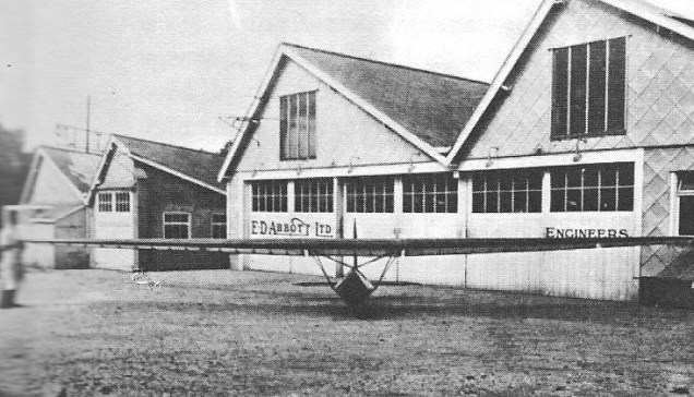
E.D.Abbot Ltd works in 1932

The Abbot-Barnes Sailplanes Ltd was established in 1931 when E.D. Abbot and L.E. Baynes entered into partnership to build Scud 1 and Scud 2 sailplanes of Mr Baynes design. The company was a subsidiary of A.E. Abbot Ltd of Farnham.

L.E. Baynes had originally started in the aircraft industry in 1916 with the Aircraft Manufacturing Co at Hendon, and later spent many years with Short Bros Lat at Rochester. In 1930 he designed the Scud 1 sailplane which was then built by Brant Aircraft Ltd (Baynes and Grant) at Croydon, Surrey. The Scud series was developed and extended by the Abbot-Baynes partnership and led to the Scud 3 / Auxiliary. This was designed to the requirements of Sir John Carden. He was a leading authority on tank design who had become interested in gliding but required a sailplane that could be put into the air without the help of others, so he suggested to Baynes the idea of a retractable engine. Carden also initiated the conversion of the Ford 10 car engine into a lightweight aero engine. Baynes installed one of these into a Flying Flea and several of these were built at the Abbot-Baynes factory incorporating many modifications by Baynes. Following several fatal accidents on the original type, a general ban was introduced and production of the Baynes version was discontinued.

During World War II the high grade skills of the work force were used to make aircraft components and by the late forties the firm was back into its original business with a series of high grade bodies on Rolls Royce, Bentley and Healey chassis.

By 1966 it was evident that Abbotts lacked the facilities to expand to cope with the increasing demand and Ford decided to take back the estate body production and to integrate it into their assembly lines at Dagenham.

Abbots had no other business to fall back upon so the firm went into liquidation.

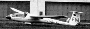
Aachen FVA 27

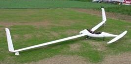
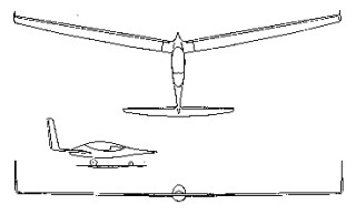
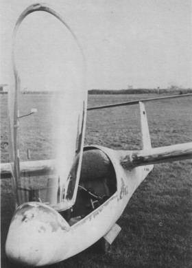
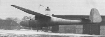
Work on the FVA27 (duck-glider) began in 1985. The FVA27 was built to determine if advantages of a canard for a glider can be achieved. According to calculations an improvement of 10% can be achieved in comparison airplane with identical main wing profile. Only the measurement by IDA-fly could show whether the theoretically determined advantages of the canard in a glider can be realized. In a flight-scientific combination, students developed and built the Aachen FVA 27 glider. IDA-flies, the controlling body of the Akafliegs, wanted to set new accents in the standard class concerned with the building, testing and the measurement of gliders. This Flugwissenschaftliche Vereinigung Aachen project covered the development of the bases, the development and building of this airplane.

Main wingspan: 15.0m
Main wing area: 7.7sq.m
Canard span: 5.0m
Canard wing area: 1.8 sq.m
Aspect ratio: 29.2
Sweep: 10.0 degs
Dihedral: 1.0 degs
Main wing profile: HQ21-M2
Canard profile: FX63-137 mod
Vertical stabilizer Height: 1.5m
Vertical stabilizer Area: 0.7sq.m
Vertical stabilizer Profile: FX38-153
Fuselage length: 4.0m
Fuselage Surface Area: 0.7sq.m
Empty Weight: 250kg
Max. Weight: 450kg
Wing loading: 32-48kg/sq.m
Best lift/drag ratio: > 45 @ 122 km/h
Seats: 1
Min sinking: 0.62 m/s @ 94 km/h
Undercarriage: Nose/main landing gear retractable
Number built: 1

Aachen FVA-21 “Wölbklappenautomatik”

On the initiative of Prof. Dr. Ing. A.W. Quick, the FVA received a research assignment on an “automatic flaps for gliders,” which was financially supported by the German Research Foundation DFG in 1972.

Profiles with flaps bring higher soaring performance compared to profiles without flaps, only when the flaps are set correctly according to the needs of the aircraft. The pilot must therefore keep an optimum value depending on wing loading and flight speed.

During cross-country flights, it is necessary to vary the flight speed depends on the average rise in thermal updrafts and the instantaneous decrease or increase in air encountered. The so-conditional permanent adjustment of the flaps constituting an additional burden for the pilot. If the adjustment of the flaps was automatic, the pilot would be relieved or the work load as with a simple-to-fly glider without flaps.

The project was developed for the DFG under Heiner Oberdörster during 1973/73.

After extensive preliminary studies it was concluded to make the regulation of the flaps dependent of the angle of attack of the aircraft. At a point in the hull wall an outwardly wind flag was attached, which gave the respective angle of attack of the aircraft in flight.

Measured at the wind flag angle was converted by a field plate differential sensor into an electrical signal and supplied to a controller. This controlled by electric valves, the adjustment of the flaps by a hydraulic cylinder until the actual value is consistent with the preset value.

For manual adjustment of the flaps the control circuit switches, as well as with landing gear and during takeoff and landing, automatically.

A an LC-3 (an all-metal glider open class with 18 m span and flaps) testbed for the automatic flaps was purchased on highly concessional terms from VFW-Fokker in 1971.

The automatic flaps were installed in the spring of 1974, and on 22 August 1974, the first flight of the complete automatics. In the course of 1974, there were more than 50 flight hours, tested by 20 different pilots.

Flying with the LC-3A ( A = automatic ) was very impressive. The flap lever turned out, as if by magic, to the optimal value. The expectations were confirmed by a long series of measurements and to everyone’s surprise, they received for the curve Flight optimal values​​.

The entire system weighed approx 20kg in the LC-3A. In conversation with some manufacturers of hydraulic devices, however, was soon clear that in reducing the weight of a compromise would be concluded between the weight savings and the consequent increase in the cost of the system. Between 1976 and 1978, Liebherr developed a hydraulic unit which was built in the LS 3a of the FVA.

Thus, the automatic flaps corresponded fully to the demands placed on them and was successfully tested in other aircraft.

Project was Heiner Oberdörster, who took care of the work to the successful completion in 1975.

Aachen FVA 20

With the decision to build a standard class aircraft, the design was already outlined in broad terms: 15m span, no lift and flaps and minimum body height 0.8m.

For the wings , the rectangular trapezoidal shape was chosen , which offers significant manufacturing advantages. The minimum surface load of 26,8kg/m² promises satisfactory flight performance even in the European weather conditions. T-tail , retractable landing gear and the proven Schempp-Hirth airbrakes were features that were maintained from the beginning.

The hull construction was begun in 1967, but the half-finished hull was for a long time in a corner of the workshop without anything happening.

Construction was half-sandwich type. Balsa wood was used as a support material for a fiberglass shell. The vertical tail fin and tailplane used the same construction, as a full-sandwich in a negative mold.

The wings were originally similar to the hull, produced in positive construction. However, it turned out that with this construction, the required high profile accuracy was difficult to achieve. Aachen changed to the negative construction. The spar is designed as a box spar, and for the spar caps roving cloth was used in the form of narrow bands.

The FVA-20 was the first fiber reinforced plastic glider built by the FVA. The FVA initially lacked the designers and builders on experience with the new material. The FVA was not discouraged by setbacks and consistently worked on the project. Among many other designers especially Uwe Solies came forward, who was project manager of the FVA-20 many years and spent many a night in the factory before the drawing board.

Since 1973, every year you could read again in the annual report that “we expect the first flight over the next racing season.” In addition to a coarse underestimate the amount of work especially the “Details”. In contrast to previous FVA-aircraft designs, made with all available work force, in the seventies with only with one project: the maintenance of the aircraft fleet, design and construction of several trailer for the newly acquired gliders took at times most of the work capacity to complete.

When finally construction began on the wings, it was discovered that the negative forms already standing in the workshop for several years set themselves so that the required surface finish and profile accuracy could not be reached. The shapes were restored to the necessary condition in winter 1975/76 which proved to be very lengthy. In March 1976, they could finally begin on the upper and lower shells of both surfaces, laminated in the form of mass inserts.

In these shells the “guts” were inserted and then the respective upper and lower shells joined together. The profile accuracy in the wing leading edge was work in the following winter.

In 1978/79 the work was continued intensively. But again there were problems in the so-called details, which caused further delays. For example, the incorporation of control organs, control levers and the actuation of the retractable undercarriage saw some problems.

During the general development some improvements were also incorporated into the design of the FVA-20. For example, the control stick and the mating of the wings is done by Hänle fashion. The surfaces were drawn together by means of a lever assembly.

on 27 November 1979 the provisional airworthiness certification by the Luftfahrt-Bundesamt was picked up by Joachim Ewald (Cassius), who was selected for the first flight. On 28 November 1979 at 10:20 Ewald lifted the FVA-20 behind towplane still unpainted. Joachim Ewald unlatched from 2200m.

The FVA-20 made a total of three flights that day and was then immediately returned to the workshop where many details were still to finished and the aircraft painted. flight testing finished with a final flight in March 1980.

Wing span: 15m

Wing area: 12.8sq.m

Empty Weight: 280kg

Gross Weight: 400kg

Wing Load: 29.7kg/sq.m

Aspect ratio: 17.58

Airfoil: FX 61-168, FX 60-126

Seats: 1

No. Built: 1

Aachen FVA-15

The FVA-15 was a Grunau Baby, modified to test lateral force control with compressed air instead of ailerons.

On the Origin and testing of bladder control was reported by Dr.- Ing. H. Stone member of the FVA in “Research and fly ” in January 1954, Issue 2:

” In terms of time the blow-through control created during the last years of the war in Aachen Aerodynamic Institute, whose leadership even then Prof. Seewald held . At the time, I got the research was to examine together with my staff , control of Lippisch . This involved a jet of compressed air , let escape the Lippisch from inside the fully enclosed blade by a plane parallel to the blade axis gap to achieve lateral force differences. the effect was good especially the strongly curved upper surface of a wing , a practical application of this control method is , however, to carry a relatively heavy compressor unit in aircraft contrary . (… )

Advantages of the through Breath Control
The hinge moments that can change with the different flight modes and speeds strong despite compensation , are variously as large dasss it no longer dominates the pilot with his physical strength , especially large aircraft must be equipped with a rowing machine . Motivated by these experiments , I made the suggestion to use a controller that is also to achieve the lateral force change with a Ausblasestrahl , but the requisite amount of air takes through a crack in the wing leading edge of the free flow of air . After some preliminary experiments that confirm the effectiveness of the arrangement , a Meßsreihe was to determine

  • the best sizes for the inlet and outlet gap
  • The best location and gap
  • the appropriate blowout down.

It was found that the inlet cross-section is greater than the Auslaßsquerschnitt be selected so that the Ausblasestrahl get a sufficiently large intensity. From the leading edge of the measured Ausblasspalt is about 2/3 chord with a Ausblasewinkel by 60 ° with respect to the outflow direction. Pressure distribution measurements in experimental profiles with and without sparging resulted in a reduction of the Unierdruckgebietes at the edge disturbed . Immediately before the Ausblasespalt pressure is reached, the pressure distribution on the undisturbed edge does not change much . As a result, the diversity is achieved by the pressure distributions at the profile flanks a corresponding shear force . (…) “

Developed by Dr.- Ing. H. Stein, the FVA began the practical testing. After several attempts to model clockwork motor models a Grunau Baby III was equipped with this control. The opinions of eminent experts also were very divided, it was feared a flow separation at the leading edge would endanger control via any small leaks on the valve bodies.

Despite the gloomy prophecies of the conversion of normal surfaces, between the outer ribs, 7 inlet slots were cut out, of which led plywood lined nozzle-shaped channels for the upper wing surface. The regulation of the amount of air happened by hinged flaps, which were based on a gasket with a thin sheet of rubber. The operation was parallel to the beam to steel pipe. For safety reasons, the normal aileron assembly had to be additionally maintained. Below the instrument panel, therefore, a hand lever was also attached to the cable pulls and bumpers, the tubes were operated in the area.

Underwriting procedures required for testing the control above a safe altitude of 500 m, so that a tug was required for the initial launch. After load testing, the test flights were made in the fall of 1953. Flight instructor Thoemssen (FVA) reported the aircraft was flying in every normal cornering without the aid of the rudder. The intensity of the built-in slots was sufficient. With simultaneous activation of aileron and blow-control, no discrimination of normal roll was revealed. Due to the low intensity of the experimental arrangement, it was even possible to cancel the effect of the fully open slots.

The flight tests proved that the new control may be superior in many cases, than conventional controllers. Mainly space and weight savings.

Aachen FVA 13 Olympia-Jollie / Nord 2000

In the spring of 1938, the FVA was invited to participate in the development of a glider that should be flown by all participants at the Olympic Games 1940 in which the glider was initially provided as an Olympic discipline. Two test machines should provisionally be built, which had to be completed by January 1, 1939.

Because of the heavy time and performance pressure FVA decided just to build the FVA-13 VI in Aachen and in parallel, the V2 by FAG Darmstadt.

Herbert Kaulbach detailed in his thesis the general design and the construction of the hull.

The following extracts are taken from the thesis of Herbert Kaulbach, which he made with Prof. Wieselsberger and presented the original copy to the archive of the FVA.

“General Guidelines”
The task is: It is to design a glider that meets the guidelines for the Olympic unit glider. In following these guidelines will be briefly summarized as You Sans Vol Moteur 1938 were drawn up by the Commission. Following the decisions of the International Olympic Committee aerobatics competitions are not allowed in the Olympic Games. Taking into account the planned tender, which provides goal -haul flights from 70-100km, a glider is to be considered, which could be in terms of performance compared with the conventional glider pattern Rhön- buzzard. The Olympic unit Glider therefore needs to be a high-performance machine. Nevertheless, many gliders are present, corresponding to these Bedingzingen, it was decided by the Commission, according to very specific aspects of a new Olympic machine to create. All interested nations to construct an Olympic – glider to February 1939 prescribed conditions. These aircraft will be presented in flight in February 1939 in Rome. On this occasion, a commission of engineers and such pilots will select the best machine and determine the future Olympic machine.

The plans prepared by the CVSM guidelines that must be taken into account in the design of the aircraft, are as follows:

  • Span 15m
  • consistency of the material : steel, plywood and pine
  • The machine should be able to get yourself some time floating on the water.
  • dive brakes, limit the maximum speed in a dive to 200 km / h.
  • When setting up the driver’s seat, it must be of a size of the pilot of 1.80 m.
  • Hull with skid without chassis
  • Driver seat with back parachute
  • Äßre cab width 600 mm
  • Empty weight 160 kg maximum
  • 95 kg payload. If necessary, the load must be added to 95 kg through the attachment of weights. The secure attachment of Zuladungsgewichten is therefore berücksichligen at the design stage.

Justification of the draft
The above guidelines and the shortness of the resources available for development, design and construction of the aircraft time make it appear necessary to establish nothing fundamentally new, but to provide a reference to an existing pattern that has especially good flying characteristics. When comparing fly is ultimately be crucial if a machine is intended for Olympic machine unit, less on performance than the flying characteristics. It therefore seems pointless at design time to lose by hiring considerations, by any means, the choice of special profiles, or the like. Can achieve the best performance. Rather, I consider it one of the basic requirements, an existing pattern recognition as I said flying capacity to investigate even as all aspects out, ie firstly to provide a mathematically perfect base and secondly to identify the simplest and most expedient in terms of structure . Since the machine may need to be copied by all the participating nations, proper drawing pad with parts lists, numbering, subdivision into modules, etc. is essential. The price for each machine in series production is expected to amount to approximately 2,500 RM.

This price also requires an intent on extreme simplicity design. A wing monoplane design brings experience, a significant additional work as a result of the complicated fuselage wing transition, where this does not elaborate creations deal, especially since the use of light metal electron or duralumin, with its use could provide cheap these transitions with fitted manufacture else, due to the condition 2 is not allowed. The simplest type, in this case, the high-decker, as the neck can be trained so that the blade is tight everywhere.

As the glider FVA -9 has the aforementioned recognized good flight characteristics, the design of this pattern bezgl. Airfoils, wings outline and high position of the rudder leaning to one another. The new draft, however, in contrast to the pattern FVA-9, which is braced, a self-supporting surface before mounting. Since the machine is said to have particularly good maneuverability, was required in the benefit calculation, at least to reach the rotational speed of the FVA-9 and get hold as far as possible to that of the 10 – FVA . More details to follow in the design specifications.

The draft stipulates : an empty weight of 120 kg. This heavier than the pattern FVA-9 (95kg)is the counterbalance design and the stringent strength requirements that are set for the Olympic unit gliders from the Commission related. To keep the landing speed in normal limits , 45 km / h and the surface load less than 15 kg / m was maintained, and elected to G / F = 14.8 kg / m² . This results in an area of F = 14.5 m².

To get mathematically correct documentation, a model was made and measured in the wind tunnel of the Aerodynamic Institute of Aachen.

In order to do proper research regarding workshop excessive production, a dummy was built, which makes it possible to determine the cheapest Beplankungsart of the forward fuselage part practical and to make the installation of the driver’s seat as low as possible and continue to answer questions of the incorporation of control organs, etc. of material importance.

The outline of the wing to the pattern of the already executed FVA-9 adapt to a large extent. In the middle part of the wing outline is rectangular and decreases towards outward straight off. The depth of the fuselage is 1.22 m and remains in constant distance 2.75 m. From 2,75 m depth tapers to them at the end of the wing = 0.44 m. The taper ratio is therefore 0.363. This ratio has been reported in a paper by Koning and Boelen as the best. The wing tip is then completed by wingtip. “

In contrast to the FVA-9, at the design the FVA-13 leaned, for a cantilever surface mounting. For mounting reasons you chose them unbalanced, ie, the left wing was attached to the hull, but the right wing was attached to this projecting stub outside of the hull.

After the construction of the “Olympic dinghy” then weighed 156 kg, and the load was exactly 95 kg. The International Commisssion selected from the three received from Germany constructors, the “Olympic tit” by DFS, so the two FVA-13 VI and V2 were in the team possession. They were destroyed in the war as well as other machines.

Since the 1940 Olympics not held because of the outbreak of war, was also the “Olympia Meise” their original purpose no longer meet. However, it was present in large numbers at home and abroad and built after the war (in France under the name 2000.
Aachen FVA-12

Several reports and lectures on the history of the FVA has remained unclear which project FVA-12 was assigned.

The author of the memorial volume “60 years of FVA” could get only on the basis about it from extensive interviews with former members and from various information. It can be assumed with near certainty that the FVA-12 had been a design for a lightweight powered aircraft as part of a thesis. Bruno Sann and Felix Kracht still remember very well that the plan to build such a power plane in the 1937/38 period was discussed in the FVA, but soon fell into disuse because of the pressure of time for project FVA-13.

It was not possible to determine who was involved in the construction of the FVA-12, in any case it was never built.