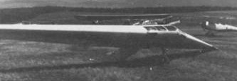
Aachen FVA-17 “Nurflügler” / Horton Ho-33

In 1954, the FVA took a research commissioned by the Federal Ministry of Transport for the purpose of operating the type certification of the Horten Ho-33 V1 flying wing powered aircraft.

The aircraft was already designed with a view to later use it as powered aircraft.

Since the VI had first flown as a glider, the proposed engine weight was installed as ballast.

Design approval for the tailless Ho33-V1 powered aircraft was achieved in 1955.

The first two test samples of Ho 33 were built by Alfons Pützer KG in Bonn. The first calculation of the data used were the following:

Wingspan: 19.20 m
Chord at the root: 3.25m
Wing area: 35,60sq.m
Net weight: 430kg
Flying weight: approx 650kg
Wing loading: 18kg / sq.m

The hull was like the wings, made of wood construction with two seats in tandem. In the rear fuselage space for the engine was provided.

Tandem undercarriage with a steerable tail wheel and two retractable support wheels, about in the inner third of the half span were fitted.
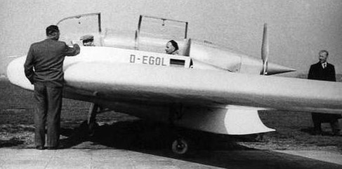
The fuselage was transferred by Pützer to Aachen in the FVA workshop, where work was started for the engine installation. The powerplant was a Zündapp “Z 9-092”.
Power: 50 hp at 2300 rev / min
Consumption: 210285 g / hp-hr
Weight: approx 65 kg

This work took about four months to complete. The fuselage was returned to Bonn and transferred to Aachen after some trial launchs at Bonn again. While at the same weight for the purpose of determining the center of gravity, it turned out that the weights were far exceeded. With an empty weight of 620 kg the flying weight was about 850 kg.

It was prepared the launch in Merzbrück some difficulties. The Horten was transported for further testing in flight 33 at Noervenich. The entire aircraft was re-measured in almost all parts. The sparse drawings not agree with the construction.

The test flights at Noervenich proved, among other things, that behavior and the start was not satisfactory.
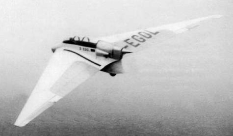
The regulations and guidelines of CAR Part 3 were applied and the new flight weight of about 900 kg; the geometrical data remained unchanged. As might be expected, the air loads were significantly higher than the original. The loads were set up as part of a student research project at the Department of Aviation.

The strength analysis was performed on the basis of newly data obtained during the survey of the aircraft resulting in air loads for the main components. The aircraft was undersized for the stresses occurring in some parts.

In particular, the suspension was of insufficient dimensions. More flights did not appear advisable because of the lack of strength. The changes required meant such an effort would exceed the financial resources so the job could not be continued. The aircraft was returned to Bonn leading to the abandonment of the project.

Later converted with a 75 hp Porsche engine.

Pützer-Horten Ho 33 V2 (001) D-EGOL suffered damage taxying at Bonn in June 1957 (owner and operator being LSV Bonn at the time). It had received a Permit to fly on 6 July 1956. The wings went to Fa.Frosch at Lutherbeck near Unna, the central fuselage to Rüdiger von Elm. The remaining parts were used to rebuild D-EJUS as engineless hybrid in the museum at Wasserkuppe.
Aachen FVA-15

The FVA-15 was a Grunau Baby, modified to test lateral force control with compressed air instead of ailerons.

On the Origin and testing of bladder control was reported by Dr.- Ing. H. Stone member of the FVA in “Research and fly ” in January 1954, Issue 2:

” In terms of time the blow-through control created during the last years of the war in Aachen Aerodynamic Institute, whose leadership even then Prof. Seewald held . At the time, I got the research was to examine together with my staff , control of Lippisch . This involved a jet of compressed air , let escape the Lippisch from inside the fully enclosed blade by a plane parallel to the blade axis gap to achieve lateral force differences. the effect was good especially the strongly curved upper surface of a wing , a practical application of this control method is , however, to carry a relatively heavy compressor unit in aircraft contrary . (… )

Advantages of the through Breath Control
The hinge moments that can change with the different flight modes and speeds strong despite compensation , are variously as large dasss it no longer dominates the pilot with his physical strength , especially large aircraft must be equipped with a rowing machine . Motivated by these experiments , I made the suggestion to use a controller that is also to achieve the lateral force change with a Ausblasestrahl , but the requisite amount of air takes through a crack in the wing leading edge of the free flow of air . After some preliminary experiments that confirm the effectiveness of the arrangement , a Meßsreihe was to determine

  • the best sizes for the inlet and outlet gap
  • The best location and gap
  • the appropriate blowout down.

It was found that the inlet cross-section is greater than the Auslaßsquerschnitt be selected so that the Ausblasestrahl get a sufficiently large intensity. From the leading edge of the measured Ausblasspalt is about 2/3 chord with a Ausblasewinkel by 60 ° with respect to the outflow direction. Pressure distribution measurements in experimental profiles with and without sparging resulted in a reduction of the Unierdruckgebietes at the edge disturbed . Immediately before the Ausblasespalt pressure is reached, the pressure distribution on the undisturbed edge does not change much . As a result, the diversity is achieved by the pressure distributions at the profile flanks a corresponding shear force . (…) “

Developed by Dr.- Ing. H. Stein, the FVA began the practical testing. After several attempts to model clockwork motor models a Grunau Baby III was equipped with this control. The opinions of eminent experts also were very divided, it was feared a flow separation at the leading edge would endanger control via any small leaks on the valve bodies.

Despite the gloomy prophecies of the conversion of normal surfaces, between the outer ribs, 7 inlet slots were cut out, of which led plywood lined nozzle-shaped channels for the upper wing surface. The regulation of the amount of air happened by hinged flaps, which were based on a gasket with a thin sheet of rubber. The operation was parallel to the beam to steel pipe. For safety reasons, the normal aileron assembly had to be additionally maintained. Below the instrument panel, therefore, a hand lever was also attached to the cable pulls and bumpers, the tubes were operated in the area.

Underwriting procedures required for testing the control above a safe altitude of 500 m, so that a tug was required for the initial launch. After load testing, the test flights were made in the fall of 1953. Flight instructor Thoemssen (FVA) reported the aircraft was flying in every normal cornering without the aid of the rudder. The intensity of the built-in slots was sufficient. With simultaneous activation of aileron and blow-control, no discrimination of normal roll was revealed. Due to the low intensity of the experimental arrangement, it was even possible to cancel the effect of the fully open slots.

The flight tests proved that the new control may be superior in many cases, than conventional controllers. Mainly space and weight savings.

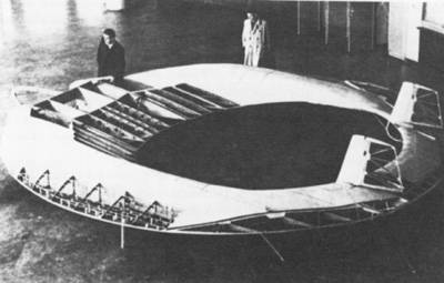
Aachen FVA 14 Ringfugel

A few years after World War 2 a Department of aircraft was re-established in Aachen, and the FVA could hope for with the right to non-teaching support. It was decided to take on a very unconventional project: the construction of a ring-wing glider.

The aim of this work was to investigate the flight characteristics of such an aircraft. Due to the absence of non-load bearing parts, it was hoped for a minimum structural weight, and reduced induced drag, because of the lack of wing tips. Furthermore, the project seemed to be a suitable object of study, with many questions of aerodynamics, strength and manufacturing. A small model a ring wing was flown successfully.

In the “Little Aachener air sports newspaper in May 1952 an article dealt with the special properties of a ring-wing. There are two main elements that allow this machine to fly: They are the wings that generate lift and the tail that controls the wings and gives them the necessary positional stability. There is the possibility that one acts as a control, a second support surface. The two wings to control one another. In this arrangement, the front face must have the larger effective angle of attack in all flight attitudes. We arrive at the concept of a stable tandem aircraft.

If during this tandem the ends of the front wing sweeps out to the rear and the rear wing exactly so that the ends of both forward pass each other, we get a ring-shaped hydrofoil system. It is not important whether this system is round, oval or triangular.

The aerodynamic characteristics of this annular wing systems are not yet fully explored. However, it is proven that you can build longitudinally stable flying machines based on these systems. It was also unrealistic to suppose as possible that the induced drag on wings ring is lower than for regular wings with the same aspect ratio.

The ring wing disc has the property that the buoyancy force to relatively large angles increases steadily with angle of attack without eruptive pulling and tearing occurs the flow. The maximum lift seems to be at an angle of approximately 30°.

Another remarkable feature of the ring-wing found the . Englishman Tilgham Richards found that the center of pressure of such wings is almost stationary during flight or that you can achieve a moving pressure center, which is practically stable up to an angle of incidence of 18°. In ring wings no case of longitudinal instability is actually known so far, although it has the centre often moved relatively far back.

Construction started in 1952 but the first wind tunnel tests are not until 1955 carried out in the wind tunnel of the State School of Mechanical Engineering

The theoretical investigations were concluded very slowly, so that the construction of full-size version was more advanced than the scientific study and calculation of the project that normally time would have allowed. In the wind tunnel tests, it was found that the ring wing compared with normal aircraft also has disadvantages.

The longitudinal stability behavior had a bad habit: In high-speed flight, the aircraft had a tendency to seek out the back attitude with a nose-down moment. Within certain limits, improving the flight characteristics resulted because of a small extension, resulting in significant losses in flight performance. These changes had caused extensive and costly modifications to the almost finished full size version. Under these circumstances, the FVA opted not to complete the full-size version. After another two years, space in the workshop was needed and the FVA14 was broken up.