A prototype Bellanca two place, side by side, tri-gear training plane flown in late 1973, but shelved in 1974, was an outgrowth of the pre-war Aeronea Chief
Post WW2
Bellance 14-19 / 17-30A Viking / 17-31 / 17-31 Super Viking

A development of the Cruisemaster, the Viking wing is made of Sitka spruce and mahogany, crafted in a separate wing plant. The fuselage is welded steel tubing covered with Dacron. It is all as durable as aluminum, and Bellanca feels that this unique method of construction is one of their major assets.

The Bellanca 260 was introduced in 1964 and produced through 1967. Built of wood and fabric, only 105 were built before production switched entirely to the Viking 300.
In 1967, a 300 hp Continental IO 520 D installation transformed the Bellanca Model 14 design into a Viking. Somewhere along the way, Vikings become Models 17 30A, but the overall aerodynamic design is true to the genius of Giuseppe Bellanca.

There are three 300 hp engine options for the Viking: a Continental IO 520 K, a Lycoming IO 540 K1E5 and the Ra¬jay turbocharged version of the Lycoming. The Viking is 3,325 pounds at gross, with an empty weight of 2,225 pounds. When a Viking is topped with 450 pounds of fuel, 75 pounds of options and 340 pounds of people, it’s easy to see how most of the 1,100 pound useful load can quickly disappear. The baggage compartment capacity is billed as 186 pounds, although it looks too small for what that weight of luggage would amount to. There is also a tube-like container running back from the baggage area toward the tail that is designed to hold 20 pounds of long equipment, such as skis or fishing poles.

Variants:
260B
Developed from the Model 14-19 Cruisemaster, with single sweptback fin and rudder replacing original tail unit.
260C
Improved version of 260B with 260hp Continental IO-470-F
Standard Viking 300
Airframe as 260C with 300 hp Continental IO-520-D or 300 hp Lycoming IO-540.
Super Viking 300
As Continental-engined Standard 300 but increased fuel and more luxurious appointments.
Super Viking 300
As Lycoming-engined Standard 300 but increased fuel and more luxurious appointments.
Standard Turbo Viking 300 / Turbo Viking
As Standard Viking but 310 hp Lycoming TIO-540 turbocharged engine.

Super Viking Model 17 30A
Engine: Continental IO 520 D.
TBO: 1,500 hrs.
Propeller: McCauley two or three blade.
Length: 26 ft. 4 in.
Height: 7 ft. 4 in.
Wingspan: 34 ft. 2 in.
Airfoil: Bellanca B.
Aspect ratio: 7.2.
Wing area: 161.5 sq. ft.
Wing loading: 20.59 lb/sq.ft.
Seats: 4.
Empty wt: 2,303 lbs.
Useful load: 1,022 lbs.
Payload with full fuel: 572 lbs.
Gross weight: 3,325 lbs.
Power loading: 11.8 lb/hp.
Fuel capacity (standard): 60 USG/360 lb lbs.
Fuel capacity (option): 75 USG/450 lb.
Baggage capacity: 186 lbs.
Baggage area: 12.08 cu. ft.
Minimum runway requirement: 1,420 ft.
Rate of climb: 1,085 fpm.
Service ceiling: 17,000 ft.
Maximum speed: 191 mph/166 knots.
Cruise, 75% power @ 7,500 ft: 187 mph/162 knots.
Economy cruise, 65% power 9,000 ft: 160 mph/139 knots.
Range @ max cruise (45 min res): 593 sm/516 nm.
Range @ economy cruise (45 min res): 715 sm/622 nm.
Duration @ max cruise (no res): 3.9 hrs.
Stall speed (clean): 74 mph/64 knots.
Stall speed (gear, flaps down): 70 mph/61 knots
Super Viking 17 31A
Engine: Lycoming IO 540 K1 E5, 300 hp.
TBO: 1,800 hrs.
Prop: Hartzell, 3 blade, constant speed, 80 inch dia.
Length: 26 ft. 4 in.
Height: 7 ft. 4 in.
Wingspan: 34 ft. 2 in.
Aspect ratio: 7.2.
Wing area: 161.5 sq.ft.
Airfoil: Bellanca B.
Wing loading: 20.6 lb/sq.ft.
Power loading: 11.1 lb/hp.
Seats: 4.
Empty wt: 2,303 lbs.
Useful load: 1,033 lbs.
Payload with full fuel: 583 lbs.
Gross weight: 3,325 lb.
Fuel capacity (standard): 60 USG/360 lb lbs.
Fuel capacity (option): 75 USG/450 lb.
Max rate of climb: 1,170 fpm.
Service ceiling: 18,200 ft.
Max speed: 196 kts.
Max cruise, 75 % power (2,400 rpm) at 15,000 ft: 165 kts.
Econ cruise, 55 % power at 15,000 ft: 150 kts.
Duration at max cruise: 4.8 hrs.
Duration at econ cruise: 6 hrs
Stalling speed, clean: 69 kts.
Stall speed, full flap: 61 kt.
Baggage capacity: 186 lbs.
Baggage area: 12.08 cu. ft.
Minimum runway requirement: 1,420 ft.
Bellanca Turbo Viking 17-31ATC
Engine: 1 x Lycoming IO-540-K1E5, 300 hp.
Seats: 4.
Wing loading: 20.6 lb/sq.ft.
Pwr loading: 11.08 lb/hp.
Gross wt: 3325 lb.
Empty wt: 2372 lb.
Equipped useful load: 886 lb.
Payload max fuel: 436 lb.
Range max fuel/75% pwr: 799 nm/4 hr.
Range max fuel / 55% pwr: 814 nm/ 5.7 hr.
Service ceiling: 24,000 ft.
75% cruise: 193 kt.
55% cruise: 144 kt.
Stall: 56-63 kt.
1.3 Vso: 73 kt.
ROC: 1170 fpm.
Min field length: 1420 ft.
Fuel cap: 360/450 lb.
Undercarriage: retractable.
Viking 300A
Engine: Continental IO-520K, 300 hp
TBO: 2000 hr
Fuel type: 100/100LL
Propeller: Hartzell CS
Wingspan: 34 ft. 2 in.
Overall length: 25 ft. 4 in.
Height: 7 ft. 4 in.
Wing area: 161.6 sq. ft
Wing loading: 20.6 lbs./sq. ft
Power loading: 11.1 lbs./hp
Wheel base: 6 ft. 8 in.
Wheel track: 9 ft.
Wheel size: 6.00 x 6 in
Max ramp weight: 3325lb
Gross weight: 3325 lb
Landing weight: 3325lb
Empty weight, std: 2185lb
Useful load, std: 1140 lb
Payload, full std. fuel: 690 lb
Usable fuel, std: US 75 gals
Equipped payload (750 miles fuel, 75 % power): 867 lb.
Cruise speed (75% power): 186mph.
Maximum range (75% power): 910mi.
Stall speed (Vso): 72mph.
Cabin width (elbow to elbow): 40.5in.
Landing gear type: Tri/Retr.
Seating capacity: 4
Cabin doors: 1
Cabin width: 41 in
Cabin height: 45 in
Baggage capacity: 186 lb
Cruise speed 75% power: 174kt
Vs: 66 kt
Vso: 61 kt
Best rate of climb (SL): 1210 fpm
Service ceiling: 20,000 ft
Takeoff ground roll: 980 ft
Takeoff over 50-ft. obstacle: 1200 ft
Landing ground roll: 835 ft
Landing over 50-ft. obstacle: 1500 ft
Turbo Viking 300
Engine: Continental IO-520-D or Lycoming IO-540, 300 hp at 2700 rpm.
Gross Weight; 3325 lbs.
Std Empty Wt; 2372 lbs.
Useful Load; 953 lbs.
Wing Area; 161.5 sq.ft.
Wing Span; 34.2 ft.
Length; 26.3 ft.
Height; 7.3 ft.
Power Loading; 11.8 lbs/hp.
Wing Loading; 20.6 lbs/sq.ft.
Fuel Capacity; 75 US Gal.
Wheelbase; 7.3 ft.
Wheel Tread; 9.0 ft.
Top Speed; 200 kts.
Optimum Cruise, 75% power, best power; 193 kts.
Stall Speed, full flaps 40 deg; 57 kts.
Take-off Run (23 deg flaps); 980 ft.
Take-off 50 ft; 1420 ft.
Landing Roll; 835 ft.
Landing Roll 50 ft; 1340 ft.
Best Rate of Climb; 94 kts.
Rate of Climb; 1170 fpm.
Service ceiling; 24,000 ft.
Fuel Consumption, 75% power, best econ; 15.7 US gph
Range 75% – 1080 sm (894 nm)
Range 65% – 1130 sm
Range 55% – 1110 sm

Bellanca 14-9 Cruisair

The original Model 14 9 Bellanca Junior, later renamed the Cruisair, started life with a 90 hp LeBlond radial engine and 140 square feet of wing area. Later versions, such as the Models 14 13 and 14 14 developed in the early ’40s, had Franklin powerplants and a healthy 161 square feet of the famous Bel-lanca B airfoil. In 1952, a 190 hp Lycoming was mated to the Cruisair’s tubular steel fuselage and the Model 14 19 Cruisemaster was born. Seven years and a new manufacturer later, the design was resurrected, modified to accommodate the 260 hp Continental IO 470 and designated the Model 14 19 3. Although a tri gear and a swept vertical stabilizer characterized subsequent Bellanca evolutions, the wing, with its Sitka spruce spar, mahogany skin and 161 square feet, remained basically unchanged except for some strengthening to accommodate the higher gross weights of the updated aircraft. In 1967, a 300 hp Continental IO 520 D installation transformed the Bellanca design into a Viking.

14 Cruisemaster
A low-wing, retractable four-seat monoplane with a good reputation for speed and lifting ability. The wooden wing tended to keep sales down and only 700 or so were built before the Cruisemaster design was updated with tricycle gear, swept fin, and a new name the Bellanca Viking.
Northern Aircraft Inc purchased from Bellanca all rights, jigs and tooling for the Bellanca 14-19 Cruisemaster four-seat lightplane. The Bellanca Model 14 was one of the classic lightplane designs, since built by several manufacturers. First production of the Northern Cruisemaster started in October 1956. Northern also supplied spares, support and modification kits for Republic Seabee amphibians after a merger with the American Aviation Corporation.
14-13-2 Cruisair

Four-seater first flown November 1945
14-30-2
Circa 1947. Fabric fuselage, controls and wings.
Engine: 150 hp.
14-19 Cruisair
Engine: 190 hp Lycoming O-435A
Span: 34 ft 2 in
Length: 23 ft
Height: 6 ft 2 in
Empty weight: 1525 lb
Loaded weight: 2600 lb
Cruise: 180 mph at 6000 ft
ROC: 1400 fpm
Range: 680 mi

Bell Aero Systems Pogo

The Bell ‘Pogo’ rocket belt two man platform.
Bell Aero Systems Rocket Belt

Bell Aerosystems Rocket Belts. These strap on devices had a pair of vectorable nozzles controlled by handlebars and enabled the wearer to be thrust over 15 m (50 ft). The only practical application of the Rocket Belt has been as a gimmick in a James Bond movie. Developed versions of the device have been used by NASA astronauts for spacewalking.
Neat and potentially useful, the rocket belt has proved difficult to control with the finesse necessary for everyday use by non experts.
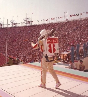
Bell Aero Systems Jet Belt
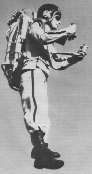
In the 1960s Bell’s Rocket belt made its public debut. The hydrogen peroxide rocket belt was compact, and also difficult to fly. The fuel is extremely pricey and it runs out so quickly that you’re limited to about 30 seconds of flight.

The Jet Belt displayed at the 1984 Olympics opening ceremony in Los Angeles.
Bell X-14
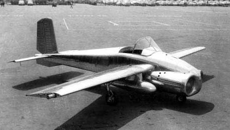
The Bell X-14 was produced as a vertical take-off prototype and achieved its first hovering flight on 17 February l957. The X-14 was originally created to explore the feasibility of operating a VTOL aircraft from a normal pilot station using standard flight instruments and references. Of equal importance, the X-14 was to demonstrate various VTOL systems and engine technologies—the aircraft was the first to demonstrate the concept of using vectored jet thrust as the only power system.
The airframe was as simple and light as possible, and was characterized by an open cockpit and fixed tailwheel landing gear. In its original form the aeroplane was powered by a pair of Bristol Siddeley Viper turbojets located side-by-side in the extreme nose of the aeroplane exhausting via nozzles on the sides of the aeroplane on the centre of gravity. For vertical take-off the nozzles were vectored directly downward, and for transition into forward flight were vectored gradually aft. The first successful transition was accomplished in May 1958, and the aeroplane was later re-engined with General Electric J85 turbojets. The X-14 made its last flight on 29 May 1981.
The X-14 successfully demonstrated that the concept of vectored jet thrust was viable, as subsequently used on the BAe/McDonnell Douglas Harrier. Flight tests using the X-14’s variable stability control system resulted in major contributions to the understanding of V/STOL handling characteristics. The X-14 also proved useful as a testbed for various unique V/STOL concepts, such as NASA’s direct side-force maneuvering system.
Over 25 pilots from around the world “previewed” V/STOL handling qualities in the X-14 prior to making test flights in other V/STOL designs. The single X-14 continued flying for nearly a quarter century before being retired to the Army Aviation Museum at Fort Rucker, Alabama. It is currently in storage at a private collection in Indiana.
Fastest Flight: 172 mph
Highest Flight: 18,000 feet (approx)
Bell X-5
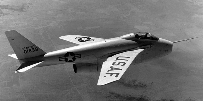
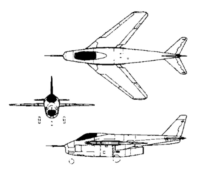
The Bell X-5 was produced to investigate the aerodynamic consequences of altering the wing geometry in flight, and first flew on 20 June 1951. Work on the two X-5s began in 1948, the basis of the design being the Messerschmitt P.1101 prototype that had almost been completed by the Germans at the end of World War II. Two X-5s were manufactured by Bell, differing from their German ancestor primarily in being able to adjust their wing sweep angle in flight. The variable sweep wing could be adjusted to 20, 40 or 60 degrees the hydraulic operating mechanism automatically compensating for the inevitable shift in the position of the design’s centre of gravity.
Powered by a 4900-lb (2222-kg) thrust Allison J35-A-1; turbojet located in the lower fuselage and exhausting under the tail boom. Special fairings were also fitted to ensure that the leading and trailing edges of the wing roots presented smooth aerofoil surfaces at all times.
The first prototype (50-1838) was completed on February 15th, 1951 and first flown on June 20th, 1951. A second prototype (50-1839) followed into the air on December 10th, 1951. Both airframes accounted for some 200 total flights with the first prototype netting 133 flights alone. All three wing sweep positions were trialed on the first prototype’s ninth flight with success.
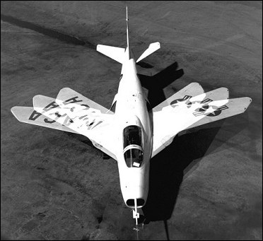
The Bell X-5 was produced to investigate the aerodynamic consequences of altering the wing geometry in flight, and first flew on 20 June 1951. Work on the two X-5s began in 1948, the basis of the design being the Messerschmitt P.1101 prototype that had almost been completed by the Germans at the end of World War II. Two X-5s were manufactured by Bell, differing from their German ancestor primarily in being able to adjust their wing sweep angle in flight. The variable sweep wing could be adjusted to 20, 40 or 60 degrees the hydraulic operating mechanism automatically compensating for the inevitable shift in the position of the design’s centre of gravity.
Powered by a 4900-lb (2222-kg) thrust Allison J35-A-1; turbojet located in the lower fuselage and exhausting under the tail boom. Special fairings were also fitted to ensure that the leading and trailing edges of the wing roots presented smooth aerofoil surfaces at all times.
The first prototype (50-1838) was completed on February 15th, 1951 and first flown on June 20th, 1951. A second prototype (50-1839) followed into the air on December 10th, 1951. Both airframes accounted for some 200 total flights with the first prototype netting 133 flights alone. All three wing sweep positions were trialed on the first prototype’s ninth flight with success.
In practice, it was found that the X-5 inherited some particularly vicious stall-spin instability characteristics. The cause was believed to be the positioning of the tail section within the design and compounded by the position of the vertical tail fin itself. As the wing sweep changed, essentially the entire aerodynamic qualities of the aircraft changed with it. The resulting action could lead the aircraft into an irrecoverable spin – this eventually occurring on October 14th, 1953 – the second prototype was lost to such a spin while running its wing sweep at 60-degrees, killing Air Force test pilot Captain Ray Popson.
The program was shelved and ultimately cancelled by the USAF. Testing did continue on with the first prototype into 1955 after which the aircraft served out the rest of her term as a chase plane until early 1958.
During Neil Armstrong’s first (and only) flight in the Bell X-5 in October 1955, the landing gear door fell off. Armstrong recalled;
“My checkout pilot was Jack McKay, and he explained that they often had trouble getting the nose gear tucked up. So, after take off, when retracting the gear, you were advised to nose over and go for about half a G. That would help get the nose gear in place, due to less download on the gear. So I attempted to do it, but it didn’t seem to be locking up. In thee meantime, I was nosing over, getting into a nose down position and, of course, the aircraft was speeding up, and I suspect that I actually ‘oversped’ the gear-limit speed, knocking the fairing door off. I never got the indication that the gear was completely retracted, so I put it back down and wasn’t able to conduct my flight plan. I never got a chance to fly the airplane again. They decided it was at the end of its research lifetime”.
The remaining Bell X-5 was handed over to the National Museum of the United States Air Force in Dayton, Ohio, in March of 1958 where it resides even today as part of the Research & Development Gallery at Wright-Patterson Air Force Base.
Engine: 1 x Allison J35-A-17 tubojet, 2223kg
Take-off weight: 4536 kg / 10000 lb
Wingspan: 5.66-9.39 m / 18 ft 7 in-30 ft 10 in
Length: 10.16 m / 33 ft 4 in
Height: 3.66 m / 12 ft 0 in
Max. speed: 1046 km/h / 650 mph
Bell X-2

Two X-2s were built by Bell Aircraft at their Niagara Falls, New York, facility. The airframes were composed primarily of stainless steel and “K-Monel,” an advanced lightweight heat-resistant stainless steel alloy swept wings.
The powerplant comprised a 15,500 lb (6804 kg) thrust throttable Curtiss-Wright XLR-25-CW-1 liquid propellant rocket.
The jettisonable cockpit can be separated from the fuselage in an emergency by an explosive charge, a ribbon-type parachute lowering the complete cockpit to a lower altitude at which the pilot can bale put.
The first X-2 was dropped into Lake Ontario on 12 May 1953 following an explosion and fire that also caused extensive damage to the EB-50A launch aircraft.
A leather gasket made by the Ulmer Company, when saturates with liquid oxygen, was so unstable that a shock of and magnitude caused the gasket to blow. A number of accidents occurred involving the X-1-3, X-1A, X-1D, and X-2, before the malfunctioning gasket was identified and a fix made.

The second aeroplane made the type’s first powered flight on 18 Novernber 1955, and recorded an altitude of 126,000 ft (38,465 m) as well as a speed of Mach 3.2 (2,094 mph; 3,370 km/h), the latter being recorded during the type’s fatal last flight on 27 Septernber 1956. This remained the highest speed at which man had flown until 1961. The aircraft experienced “inertia coupling” resulting in complete loss of control—pilot Milburn Apt was killed in the accident. No examples of the X-2 survive.
Dick Day warned his air force associates not to push ahead so fast with the X-2, piloted by Ivan Kinchloe, Frank ‘Pete’ Everest, and Milburn G. Apt. Data from their work was confirming evidence from NACA wind tunnel tests that the X-2 would experience ‘rapidly deteriorating directional and lateral (roll) stability near Mach 4’. On 25 April 1956, the X-2 broke the sound barrier for the first time. Less than a month later, it flew past Mach 2. By mid-summer it was pushing Mach 3. When Mel Apt took the X-2 up on 27 September 1956, for his very first flight in the aircraft, his flight plan called for ‘the optimum maximum energy flight path,’ one that would rocket him past Mach 3 – and into roll coupling. The fatal crash happened just as Dick Day thought it might. At 65,000ft and a speed of Mach 3.2, Apt lost control of the X-2 due to roll coupling and became unconscious. By the time he came to it was too late. He died instantly when the plane hit the desert floor.
The two X-2s achieved 20 flights in total between 1952 and 1956.
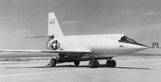
Engine: 1 x Curtiss-Wright XLR25-CW-1 rocket engine, 6804kg
Wingspan: 9.75 m / 31 ft 12 in
Length: 13.41 m / 43 ft 12 in
Height: 4.11 m / 13 ft 6 in
Max. speed: M3.2 (2,094 mph; 3,370 km/h).
Ceiling: 38405 m / 126,000 ft / 38,465 m
Crew: 1

Bell 65 VTOL
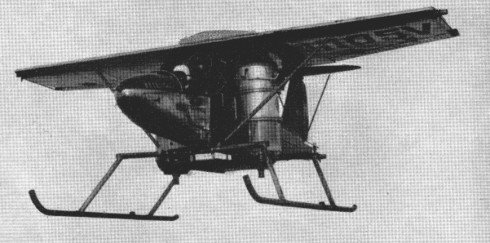
The Bell 65 VTOL was built to test the practicability of rotatable turbojets providing thrust for both lift and forward propulsion. Two turbojets, which raised it off the ground for take-off, could be turned 90 degrees in the air to provide forward thrust, leaving the fixed wing to provide lift.
Constructed largely from existing parts, power was provided by two 1000 lb thrust Fairchild J44 turbojets and one Continental-Turbomeca Palouste compressor.
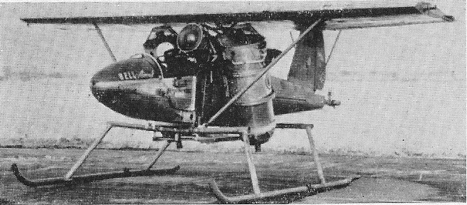
Control at low-speed being obtained from compressed-air jets at the tail and wingtips fed by the Palouste.
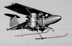
Engines: two x 1000 lb thrust Fairchild J44 turbojet
Wingspan: 26 ft
Wing area: 130 sq.ft approx.
Length: 21 ft
Loaded weight: 2200 lb approx.

