Eiri Pik-20 / Siren Pik-20

Pik-20B

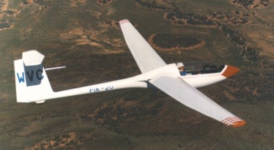
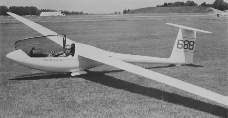
The single-seat high performance Unrestricted Class PIK-20, design work on which, by a team headed by Pekka Tammi, started on 1 May 1971, the first of two prototypes making its first flight on 10 October 1973. Three prototypes were built, followed by 24 of the first series.

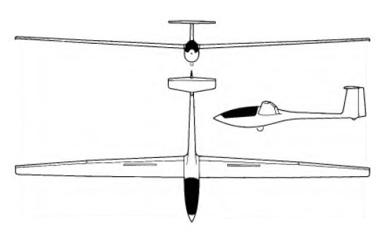
The Pik-20 is a 15 m. racing class, all-fiberglass sailplane with water ballast, retractable gear and 90 degrees trailing edge flaps for landing. Finnish certification of the PIK-20 was granted on 20 June 1974, followed by FAA certification exactly a year later.

There is a retractable Tost monowheel with a drum brake as well as a tailwheel. The T-tail is of similar construction to the wings, and the fixed-incidence tailplane has a one-piece elevator.

After over 425 were built, the PIK-20 was soon followed by the PIK-20B in 1975, the main production version, which had an increased gross weight, greater water ballast capacity of 309lb, interconnected flaps and ailerons for improved performance, which could be retrofitted to earlier models, and a pneumatically sealed sideways opening cockpit canopy. From aircraft No 20100 carbon-fibre spars became available as an option, but later became standard, reducing the empty weight to 496 lb. The PIK-20A designation was an unofficial designation used to distinguish the PIK-20 from the PIK-20B.

Ingo Renner won the 15 m. class at the 1976 World Championships at Rayskala, Finland in a B-model, and others finished 2nd, 3rd and 5th.

PIK-20B

The PIK-20C designation was not used, but reserved for the JT-6 proof-of-concept prototype for PIK-20E.

The PIK-20C designation was not used, but reserved for the JT-6 proof-of-concept prototype for PIK-20E.

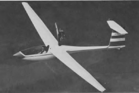
The PIK-20D, first flown on 19 April 1976, superseded the B, and this has carbon-fibre spars as standard, and is fitted with Schempp-Hirth air brakes and improved flaps, or ‘flaperons’, which act as both flaps and ailerons for enhanced performance. The flaperons, operate differentially for roll control and deflect from -12 degrees to +16 degrees for cruise or approach control. The cockpit is enlarged and its layout improved, and carbon-fibre is also used to reinforce the fuselage. The wings and tail surfaces are glass-fiber reinforced plastic (GRP) sandwich with PVC core. The fuselage is a GRP monocoque structure reinforced with ribs of carbon fiber.

The -20D features carbon fiber spar caps and carbon reinforcement strips at critical locations in the fiberglass monocoque fuselage. The PIK-20D-78 production models the nose profile was sharpened, the tail moved 5 inches forward and fuselage fairings recontoured to reduce drag.

PIK-20 production was undertaken by Eiriavion O/Y, and by January 1979 a total of 149 PIK-20Bs and 150 PIK-20Ds had been delivered. The type soon made its mark in competitions, winning the first three places in the Standard class at the 1976 World Gliding Championships in Finland, and also winning several national championships.

PIK-20E

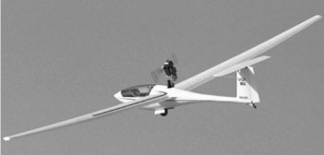
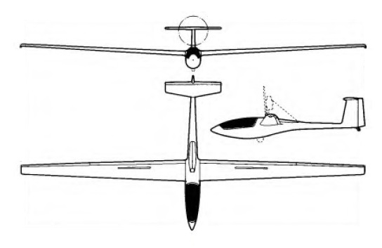
The PIK-20E is a -D sailplane with a retractable Rotax two-cylinder two-cycle engine, developed by Jukka Tervamaki, the chief designer of Finland’s Eiriavion O/Y, to meet the OSTIV airworthiness regulations for powered sailplanes. A manual crank handle requires about 15 turns to deploy or retract the engine and propeller.

Initial PIK-20E were powered by the Rotax 501 but the PIK-20E II featured a Rotax 505 (two spark plugs per cylinder). The Rotax 503 500cc two-stroke two-cylinder engine produces 43 hp at 6,200 RPM. With double carburetors and resonance exhaust system, the whole snowmobile engine has been redesigned and built to aircraft requirements. The Hoffmann two-blade wooden propeller is belt driven giving a 1:2 reduction. When not in use, the power plant is retracted into the fuselage by a manual crank and lever in the cockpit wall. The glider features fiberglass monocoque construction. Half of the fuselage/wing fairing has been taken to the wing so that the main rib and wing spar are 20 nm higher in order to save weight. The wings, flaps, and complete tail are of sandwich construction with fiberglass skin and PVCfoam core. Wing spars are made of carbon fiber. The PIK boasts a maximum L/D ratio of 40 to 1. With power on, takeoff can be accomplished in less than 1,000 feet if a 50′ obstacle has to be cleared and rate of climb is 787 fpm. Cruising speed is 84 mph at 75 percent power, burning 4.4 gph from the 8.7-gallon fuel tank.

The prototype PIK-20E was powered by a 30hp Kohler 440cc engine and first flew on 2 October 1976, making a four hour flight of which two hours were spent soaring with the engine retracted. The production prototype made its first (aero-tow) flight on 16 March 1978, and its first powered flight two days later, and series production began shortly after.

There is an electric starter for the engine, and the fuel tank behind the pilot’s seat holds 7.3 Imp gallons. Apart from the engine, the PIK-20E is very similar, structurally and otherwise, to the PIK-20D, with a longer nose, 25% more tailplane area, small fixed wheels at the wing tips and a rubber-sprung tailwheel now mounted on a steel sprung skid moved behind the fin spar to the base of the rudder so as to make it steerable; the water ballast capacity (an optional feature) is smaller than the D’s.

Eiri PIK-20E

The PIK-20F was available as a 15m Class variant (with 308lb of water ballast) or a Club Class variant, the latter having a fixed monowheel. The PIK-20F has carbon-fibre spars, a modified wing profile, a lower drag fuselage, a forward-opening carbon-reinforced cockpit canopy, a carbon-reinforced cockpit area, and a new wing/fuselage epoxy finish.

Production rights for the PIK-20E were sold in 1981 to the French firm Siren SA. Altogether 102 PIK-20Es had been built in Finland when production ceased there in the spring of 1981. By the spring of 1981 a total of 409 PIK-20s of all versions (including the motorised PIK-20E) had been built, of which 85% were for export.

Gallery

PIK-20B
Wing span: 15m / 49.2ft
Length: 21 ft 10 in
Wing area: 10sq.m / 107.6sq.ft
Aspect ratio: 22.5
Empty Weight: 220kg / 485lb
Payload: 140kg / 308lb
Gross Weight: 450kg / 992lb
Wing Load: 45kg/sq.m / 9.2lb/sq.ft
Water Ballast: 140kg / 308lb
Seats: 1
Lift / drag at 53 kt: 40
L/DMax: 42 @ 110 kph / 63 kt / 73 mph
MinSink: 0.66 m/s / 2.16 fps / 1.28 kt 44 kts
Max airspeed 130 kt
Rough air speed 130 kt
Stall 31 kts
Airfoil: Wortmann FX 67-K-170/150

PIK-20D
Span: 49 ft 2.5 in/ 15.0 m
Length: 21 ft 2 in / 6.45 m
Height: 4 ft 6.75 in / 1.45 m
Wing area: 107.6 sqft / 10.0 sq.m
Aspect ratio: 22.5
Wing section: Wortmann FX-67-K-170/150
Empty weight: 480 lb / 220 kg
Max weight: 992 lb / 450 kg
Water ballast: 309 lb / 140 kg
Max wing loading: 45kg/sq.m / 9.21 lb/sq.ft
Max speed: 181 mph 158 kt / 292 km/h (in smooth air)
Stalling speed: 32 kt / 60 km/h
Max aero-tow speed: 118 mph / 130 kt / 240 km/h
Min sinking speed: 2.17 ft/sec at 53.5 mph
Min sinking speed: 0.56 m/sec / 1.84 ft/sec at 39 kt / 73 km/h
Best glide ratio: 42:1 at 73 mph / 63 kt / 117 km/h

PIK-20E
Engine: Rotax 503, 32 kW / 43 bhp
Wing span: 15m / 49 ft 2.5 in
Wing area: 10.0 sq.m / 107.6 sq.ft
Airfoil: Wortmann FX 67-K-170/150
Aspect ratio: 22.5
Length: 6.53 m / 21 ft 5 in
Height: 4 ft 8.75 in
Empty Weight: 310kg / 684 lb
Payload: 160kg / 352 lb
Gross Weight: 470kg / 1036 lb
Wing Load: 47kg/sq.m / 9.6 lb/sq.ft
Water Ballast: 80kg / 176 lb
L/DMax: 40 @ 110 kph / 63 kt / 73 mph
MinSink: 0.66 m/s / 2.16 fps / 1.28 kt at 55 mph / 42 kt / 77 km/h (power off)
Max speed: 177 mph 154 kt / 285 km/h (power off)
Max cruising speed: 84 mph (power on)
Stalling speed: 36 kt / 66 km/h
Rate of climb: 4.0 m/sec / 13 ft/sec
Take-off run: 1,640ft to 50ft
Seats: 1

Pik-20E

Eipper Bamboo Bomber

The wing is a version of the Bat-Glider with changes for sure. Taras Kiceniuk made a Batso version with a change from Bat-Glider (published plans by Jim Foreman….which themselves were developed from photos and notes given Foreman by Richard Miller of Millers’s earlier Bamboo Buttfly). Eipper’s Penninsula Hang Gliding crew made the bamboo and polyethelene glider to fly off the Torrance Beach sand cliffs in 1971. Materials used: bamboo canes, string, sillage bags type polyethylen sheets…

Built by Dick Eipper, Ken Seinmetz, and Chris Parker out of bamboo, visquine (a heavy polyethelene sheeting) and plastic coated clothes line…materials purchased by Dick.

That was the summer or 69. That’s Dick Eipper as the pilot, Mark Tolar as the one at the keel and Steve Wilson on the left side of the glider. A few months later Dick and Steve founded EipperFormance Hang Gliders. Ayear and a half later they incorperated and brought Dave Muehl, Mike Hutter, Bob Lovejoy and Dave Cronk on as partners.

These sand cliffs were quite close to the water’s edge at Torrance Beach in Southern California and the water was the objective although they rarely made it that far. Smaller bodies sometimes did. It had no battens but surely needed them as the trailing edge flapped alot and made quite a noise. They didn’t think of it. There were also a few quite spectacular crashes, Steve Wilson, being one of them. He came up with torn Levis, scrapes and bruises, and a face full of sand. That’s why they chose that spot it had all the right characteristics…..soft, or relatively so, landing area and good onshore winds.

Eipper High Tailer

The High-Tailer, designed by Bob Lovejoy, had a height of 1.2 meters and a wingspan of 9 meters. The High-Tailer had two inclined vertical fins starting from the control bar and passing through the trailing edge of the wing (almost identical to the Quicksilver) and finished above the wing. A horizontal plane connected the two drifts.

The design had some directional control problems (it would almost always fly straight ahead, very stable), and the control bar/vertical/horizontal arrangement was somewhat flexible. It was a four sides parallelogram structure, so had little inherent stiffness.

The origin of the Quicksilver can be found in Bob Lovejoy’s High-Tailer design. The High-Tailer and early Quicksilvers all had a 4 foot chord and 30 ft span.

The original Quicksilver (later called the “A” model) was built from the High-Tailer. The twin verticals and high mounted horizontal were replaced with an “A” frame off the trailing edge of the wing, back to a fixed horizontal and a “C” frame rudder (no fixed fin). As the trailing edge of the “C” frame was unsupported, the rudder distorted a lot, but it was very effective at directional control, and the glider responded through dihedral effect (Cl-beta). The “C” frame rudder got replaced with a different “D” frame rudder which solved the distortion problem.

Eipper-Formance Quicksilver (Hang-glider) / Cronk Quicksilver

Designed in 1972 as a hang glider by Bob Lovejoy.

The popular Quicksilver monoplane hang glider was developed it into a very good power glider. With its twin-boom tail support structure, an engine mounted from the wing center section it offers gentle and forgiving flight characteristics and is generally foot-launched, though landing gear can be added.

Quicksilver B

The origin of the Quicksilver can be found in Bob Lovejoy’s High-Tailer design. The High-Tailer and early Quicksilvers all had a 4 foot chord and 30 ft span.

Eipper-Formance Quicksilver (Hang-glider) Article

The original Quicksilver (later called the “A” model) was built from the High-Tailer. The twin verticals and high mounted horizontal were replaced with an “A” frame off the trailing edge of the wing, back to a fixed horizontal and a “C” frame rudder (no fixed fin). As the trailing edge of the “C” frame was unsupported, the rudder distorted a lot, but it was very effective at directional control, and the glider responded through dihedral effect (Cl-beta). The “C” frame rudder got replaced with a different “D” frame rudder which solved the distortion problem.

The Eipper guys thought to load test the Quicksilver and the failure occured at very low G, about 3.5 Gs, between the trailing edge flying wire and the center section. Also, the single upper wire to the tail didn’t
provide much lateral support to the rudder loads. These led to the the first improved model of the Quicksilver, called the “B.” A wire was added from the control bar to the trailing edge of the wing (increasing the G limit to about 5.5), the “A” frame of the tail group gained a straight section between the horizontal and the rudder
(making a square “U” section) and a second upper wire was added from the kingpost to the tail (one wire to each end of the squared-off “U”). The result was the best of the early model Quicksilvers, as a flying machine and structurally.

Dec 73 – Mar 74

The Quicksilver B, designed by Bob Lovejoy, was available as ready-to-fly, kit form, or as plans. The airframe is aircraft aluminium tubing, wings and tail surfaces are dacron covered. Pitch is weight-shift controlled, while the swingseats connected to the rudder controls turns.

A Quicksilver B kit in 1974 cost $545 and plans sold for $5. Ready to fly the Quicksilver B cost $965. A custom colour wing cost an additional $30.

There were homebuilt versions including one in 1974 with polyethylene covering instead of sail cloth.

Mark Clarkson, flying a Quicksilver in the spring of 1974, flew seventeen miles (measured as a straight line between take-off and landing). The farthest anyone had flown in a hang glider.

The next Quicksilver improvement was increasing the span (from 30 ft to 32 ft), increasing the chord (from 4 ft to 5 ft), and enlarging the tail (the rudder lost its characteristic “swept” leading edge). The wing also gained square tips (cf the “tapered” tip of the HT/QsA/QsB) to make the Quicksilver C model. This model also had a much reduced camber of the airfoil (the High-Tailer through Quicksilver B model had a “670-15” airfoil, which was made by bending a thin aluminum tube for one-half of it’s length over a 670-15 car tire; it was about 12% camber; the C and later models had about an 8% camber, again, IIRC). This was the same model that Jack Schroeder and Dave Cronk flew in the (much delayed) 1974 Nationals. The C model seemed to be the most prolific of the hang glider models.

Cronk Quicksilver B

All HT and Qs models to this point had a tube for a trailing edge. An experiment was made of moving the trailing edge spar forward, and making a thin trailing edge of fabric only. The leading edge pocket was also made VERY large (maybe about 50% of the chord). Dave Cronk said it ruined the stall characteristics (very sharp and abrupt), but penetration went WAY up. This may have been called a “D” model. Later still the leading edge pocket was made even larger to enclose the leading and trailing edge spars (about 80%) making a double surface airfoil. This model was a rocket in Cronk’s hands, though it appears none were sold to customers.

Dave Cronk with a rudder connected to his harness via cords. Pitch is weight shift controlled.

First year motorized 1976.

Hang-glider.
L/D: 7-1.
Cruise: 18 25 mph.
Gross wt: 395 lbs.
Empty wt: 155 lbs.
Max pilot wt: 220 lbs.
Takeoff dist: 40-50 ft.
ROC: 250 fpm.

Quicksilver B
Wingspan: 30 ft
Wing area: 116 sq.ft
Weight: 56 lb
Cruise speed: 22 mph
Max speed: 32 mph
Stall speed: 17 mph
Max glide ratio: 7-1
Min sink: 250 fpm

Cronk Quicksilver B
Wing area: 10.80 m²
Wing span: 9.15 m
Aspect ratio: 7.75
Hang glider weight: 25 kg
Minimum speed: 35 km/h
Maximum speed: 50 km/h
Max glide ratio (L/H): 7
Minimum sink rate: 1.3 m/s

Eipper-Formance Cumulus

Cumulus 10

A 1977 high performance flexible wing. The Dave Cronk designed Cumulus has folding tubes for truncated wingtips. There are no battens, and the flying wires are adjustable for seated or prone.

The Cumulus V is a high-aspect ratio Rogallo hybrid with tip extensions, shaped keel and large, tapered, leading edge pockets. It is controlled solely by means of weight shifting. It is characterised by a higher wing loading and a faster cruise speed than for a standard Rogallo, giving it improved penetration. The stall is described as being gentle, with the nose dropping through at about 16 mph.

Take down and set up times should be within 10 minutes and the Cumulus V may be folded and transported like a standard Rogallo.

Cumulus V

The Cumulus 5B continues the development started in October 1974 and features a very lightweight frame, shaped keel, squared wing tips, and a roached sail with two battens per side. A fully battened sail was optinal. The light frame and small sail area gave fast and responsive control.

All aluminium components are fully anodised, and the triangle bar is adjustable to two positions for seated or prone flying. Spar saddles are brushed onto tubes for better distribution of loads, and tensioners are used on the top rigging, replacing turnbuckles. Wingpost blades are standard equipment, eliminating spar deflection.

Cumulus 5B

The Cumulus 5B airframe main tubes are 2044-T3 1.75in x .035 aluminium with the exception of the crossbar which is 6061-T6 1.75in x .049. All tbes are clear anodised, and all stress points are internally sleeved. Triangle bar is 6061-T6 1in x .083 black anodised aluminium.

Rigging cable is 3/32in vinyl coated stainless steel throughout. All ends are double nico pressed. Clip locking AN turnbuckles are used on the wingpost wires. All fittings are polished stainless steel and black anodised aluminium. Nuts and bolts are to AN specification.

The Haowe & Bainbridge 3.8oz stabilised dacron sail was available in 11 colours. A nine foot leading edge pocket was applied to eliminate bias stretching, all seams double zig-zag stitched, and all stress points heavily reinforced. Clear windows, special inserts, logos, air brushing, extra battens etc were available on request.

Seated harness and supine harness use individual leg straps and a wide back strap is used on both systems with the supine having fibreglass stiffeners added to aid comfort. The prone harness fully supports the pilot and is padded at all pressure points. It can also be flown for short periods in a seated position. Both systems use 5500 lb tested nylon webbing in load carrying positions.

Cumulus 5B painted by Mendij

1975 world champion David Cronk organised a mass drop of eight Cumulus VB’s from a 320 ft high hot air balloon over California.

Cumulus V
Wingspan: 29 ft 6 in
Wing area: 165 sq.ft
Aspect ratio: 5.2
Keel length: 12 ft
Leading edge length: 18 ft
Nose angle: 109 degrees
Billow: 2.5 degrees
Empty weight: 39 lb
Max flying weight: 240 lb
Useful load: 201 lb
Best L/D: 7-1
Min sink: 250 fpm
Stall speed: 16 mph
Cruise: 25 mph

Cumules 5B 16
Leading edge: 16 ft
Keel length: 9.5 ft
Wing span: 26.1 ft
Wing area: 136 sq,ft
Aspect ratio: 5.0
Nose angle: 110˚
Sail billow: 2˚
Weight: 37 lb
Pilot weight: 100-140 lb
Takeoff speed: 12-15 mph
Stall speed: 15-16 mph
Max speed: 35 mph
Best glide ratio (L/D): 7-1
Best L/D speed: 25 mph
Min sink: 250 fpm

Cumules 5B 17
Leading edge: 17 ft
Keel length: 9.5 ft
Wing span: 28 ft
Wing area: 145 sq,ft
Aspect ratio: 5.4
Nose angle: 110˚
Sail billow: 2˚
Weight: 38 lb
Pilot weight: 120-160 lb
Takeoff speed: 12-15 mph
Stall speed: 15-16 mph
Max speed: 35 mph
Best glide ratio (L/D): 7-1
Best L/D speed: 25 mph
Min sink: 250 fpm

Cumules 5B 18
Leading edge: 18 ft
Keel length: 10.5 ft
Wing span: 29.5 ft
Wing area: 165 sq,ft
Aspect ratio: 5.3
Nose angle: 110˚
Sail billow: 2˚
Weight: 41 lb
Pilot weight: 150-200 lb
Takeoff speed: 12-15 mph
Stall speed: 15-16 mph
Max speed: 35 mph
Best glide ratio (L/D): 7-1
Best L/D speed: 25 mph
Min sink: 250 fpm

Cumulus 10
Wing span: 10.2 m
Hang glider weight: 20 kg

Cumulus 5B

Eipper-Formance Flexi 2

The Flexi 2 replaced the original Flexi Flier. It features fibreglass battens on each wing tip which allows wider tip chords, allowing a flatter sail cut while maintain docile slow speed and parachuting stall characteristics.

All aluminimum components are anodised, and the triangle bar is adjustable to two positions for seaed and prone flying. Spar saddles are bushed onto tubes for better distribution of loads, and tensioners are used on top rigging, replacing turnbuckles. Wingpost blades are standard equipment, eliminating spar deflection.

The 18ft, 20ft and 22ft Flexi 2’s use 1.5in, 1 5/8in and 1.75in .049in diameter tubing respectively. All tubing is clear anodised 6061-T6 aluminium. All stress points are reinforced with internal sleeving and all holes are bushed. The Triangle bar is 6061-T6 ix.083in black anodised aluminium.

The rigging is 3/32in 7×7 stainless steel wire rope throughout and is fully white vinyl coated. All ends are double nici pressed. Wire tensioners are used on the top rigging, while clip-locking AN turnbuckles are used n the wingpost wires.

All hardware is polished stainless steel and black anodised aluminium. Nuts and bolts are all to AN specifications.

The sail is Howe & Bainbridge 3.8ox stabilised dacron available in 11 colours. All seams are double zig-zag stiched and stress points are reinforced with 9oz cloth.

Seated harness and supne harness use individual leg straps and a wide back strap is used on both systems with supine having fibreglass stiffeners added for comfort. The prone harness fully supports the pilot and is padded at all pressure points. Both systems are 5500 lb test nylon webbing in load carrying positions.

The Flexi Flyer 3 was for Advanced pilots.

Flexi 2 18
Leading edge: 18 ft
Keel length: 13 ft
Wing span: 26 ft 6 in
Wing area: 165 sq,ft
Aspect ratio: 4.25
Nose angle: 95˚
Sail billow: 2.5˚
Weight: 37 lb
Pilot weight: 110-50 lb
Takeoff speed: 10-15 mph
Stall speed: 10-14 mph
Max speed: 35 mph
Best glide ratio (L/D): 6:1
Best L/D speed: 23 mph
Min sink: 290 fpm

Flexi 2 20
Leading edge: 20 ft
Keel length: 14 ft 6 in
Wing span: 29.6 ft
Wing area: 205 sq,ft
Aspect ratio: 4.25
Nose angle: 95˚
Sail billow: 2.5˚
Weight: 41 lb
Pilot weight: 140-180 lb
Takeoff speed: 10 mph
Stall speed: 10-14 mph
Max speed: 35 mph
Best glide ratio (L/D): 6:1
Best L/D speed: 23 mph
Min sink: 290 fpm

Flexi 2 22
Leading edge: 22 ft
Keel length: 16 ft 6 in
Wing span: 32 ft 6 in
Wing area: 245 sq,ft
Aspect ratio: 4.29
Nose angle: 95˚
Sail billow: 2.5˚
Weight: 46 lb
Pilot weight: 170-220 lb
Takeoff speed: 10-15 mph
Stall speed: 10-14 mph
Max speed: 35 mph
Best glide ratio (L/D): 6:1
Best L/D speed: 23 mph
Min sink: 290 fpm

Eipper-Formance / Eipper Aircraft 

1974

Eipper-Formance Inc

Box 246

Lomita

Califirnia 90717

USA

Previously called Eipper‑formance, after Dick Eipper, this San Marcos company was renamed Eipper Aircraft in October 1982.

1982: Eipper Aircraft, 1080 Linda Vista Drive, San Marcos, California 92069, USA.

In 1983 the plant moved to larger quarters in Temecula, California, to accommodate increased production, a worldwide dealer network and more than 100 employees.

1995: PO Box 1572, Temecula, CA 92593, USA.

Eiloart & Mudie Small World

The Atlantic Ocean was for many years the greatest challenge in ballooning history. A group of four British balloonists, Colin Mudie, his wife Rosemary, Bushy Eiloart and his son Tim, planned to take on the Atlantic crossing, using their experience as sailors. They decided to take an east to west route, leaving from Tenerife heading towards a central location on the east cost of the United States.

The crew, who designed the ballon and planned the whole voyage consisted of Arnold “Bushy” Eiloart (Commander), his son Tim (Radioman), Colin Mudie (Navigator), and his wife Rosemary Mudie (Photographer). They had a gondola (basket) specifically built for the journey which was made from reinforced polystyrene and measured 15ft x 8ft. The gondola was attached to the envelope with quick release cables for ease in the case of an emergency. A special feature of the design is that the basket is designed as a sailing boat, to be used if the party were to be forced to ditch in the sea. The crew had designed, constructed and learnt to fly the balloon with little or no assistance as England at this time did not have even one qualified balloon examiner.

The attempted crossing of the Atlantic from Tenerife to Barbados in the hydrogen balloon “Small World” in December 1958 was filmed.

The film opens with scenes of testing the balloon prior to the actual attempt, with the balloon being inflated at Cardington, outside airship hangars. Wing Commander Ralph Booth, captain of the R-100 airship supervises the testing, and is also involved in heading the launching crew.

The balloon was launched from Tenerife, in the south of the island, at 1 o’clock in the morning of 12th December 1958, after being frustrated and delayed by high winds and bad weather. There are various scenes of the take off, and activities in the basket. They fly the balloon for 94 hours and 1200 nautical miles, before being forced to ditch in the sea through problems with maintaining altitude in a ferocious storm and having to sail the rest of the way to Barbados, which took them about 3 weeks. There are numerous scenes on the small “boat” with rationing, sailing and using instruments such as a chronometer. They eventually land in Barbados (another 1,450 miles) on 5 January 1959, towed in by a fishing boat which charged them 50 dollars. A large crowd greet them, with people running along the beach, as the populace had been alerted to their impending arrival by reporters and local radio.

The Small World broke all existing balloon duration records.

EFW N-20 Aiguillon / N-20.01 /N-20.2 Arbalète

The N-20 “Aiguillon”

The EFW N-20 “Aiguillon” (English: Stinger) was Switzerland’s first jet fighter aircraft. The Swiss Federal Aircraft Factory developed a design for a four-engined swept winged fighter following the end of the Second World War. The aircraft was to be powered by four turbofan engines buried in the wings, with the bypass air feeding cold-air pipes each side of the engine, being routed through a combustion chamber where additional fuel could be burned as a form of reheat, or deflected though large slots on the upper and lower wings to act as aerodynamic flaps or thrust reversers. Two engines could be shut down in flight to increase range. It was planned that the N-20 would carry its armament in a detachable weapons bay, capable of carrying large loads of cannons, rockets or bombs.

It was initially planned that the aircraft’s engines would be designed and built by the Swiss company Sulzer, but they abandoned this project in 1947, so the British Armstrong Siddeley Mamba turboprop was chosen as the basis for the N-20’s engines, with the propeller reduction gear replaced by a low pressure compressor.

A 3/5 scale wooden glider, the EFW N-20.01 was built to allow testing of novel wing shape, this flying on 17 April 1948. Although the glider was destroyed in a landing accident, it had successfully proven the design, and was followed by a similar sized powered test aircraft, the EFW N-20.02 Arbalète (Crossbow), powered by four 0.98 kN (220 lbf) Turboméca Piméné, mounted above and below the wings, this flying on 16 November 1951. It proved to have good manoeuvrability and reached a maximum speed of 750 km/h (466 mph).

The full scaled aircraft was estimated to have a maximum speed of 1,095 km (680 mph), but the initial converted Mamba, the SM-1, which was test-flown under a de Havilland Mosquito in 1948 and was the first turbofan to fly, did not generate adequate thrust. Considerable further work was required for the definitive two-shaft SM-5 engine, which was meant to generate 14.7 kN (3,300 lbf) thrust. The prototype was completed in 1952 and, fitted with four SM-1 engines, flew briefly during a taxi test on 8 April 1952, but the development of the engine and the N-20 aircraft was cancelled soon afterwards.

N-20.2 Arbalète

Gallery

N-20
Powerplant: 4 × Armstrong Siddeley Mamba turbofan, 6.2 kN (1,400 lbf) thrust each
Length: 12 m (41 ft)
Wingspan: 12.60 m (41 ft 4 in)
Height: 4 m (12 ft)
Wing area: 53 m2 (570 sq ft)
Gross weight: 8,709 kg (19,200 lb)
Crew: 1

F+W N-20-2 Arbalète
Engines: 4 x Turbomèca Piméné jet, 100 kp thrust
Length: 7.53 m
Span: 7.56 m
Height: 2.30 m
Wing area: 12.63 m²
Empty weight: 1540 Kg
MAUW: 1800 Kg
Useful load: 190 Kg
Max. speed: 720 km/h
ROC: 5m / s
Ceiling: 8000 m
Range: 250 Km

F+W N-20.10 Aiguillon
Engines: 4 x Swiss Mamba SM-01 turbofan with plenum chamber burners and thrust reversers,
Thrust: 620 kp
Length: 12.5 m / 41 ft 0 in
Wingspan: 12.6 m / 41 ft 4 in
Height: 3.13 m / 10 ft 3 in
Wing area: 54.0 sq.m / 581.25 sq ft
Max. speed: 1000 km/h / 621 mph
T/O weight: 9000 kg
Max. speed: 1000 km/h
Ceiling: 14000 m