USA
Hang glider builder circa 1975-6
USA
Hang glider builder circa 1975-6
In¬terest in forward swept wing was revived in the early 1960s when the German Hamburger Flug¬zeugbau (HFB) company made market studies on the prospects for business jet aircraft. These studies indicated a potential demand for a seven seater and that a forward swept wing offered advantages for this particular size of aircraft. The HFB chief designer was Hans Wocke. Designer of the war-time Junkers Ju 287, and the commercial sales manager of HFB was Sieffiried Holzbaur, the Ju 287 test pilot.
In the development of the Hansa Hamburger Flugzeugbau GmbH co-operated with several other companies, the Dutch Fokker concern being responsible for the typical forward-swept wing and the Spanish CASA concern for the rear fuselage and tail.
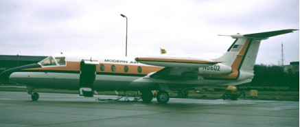
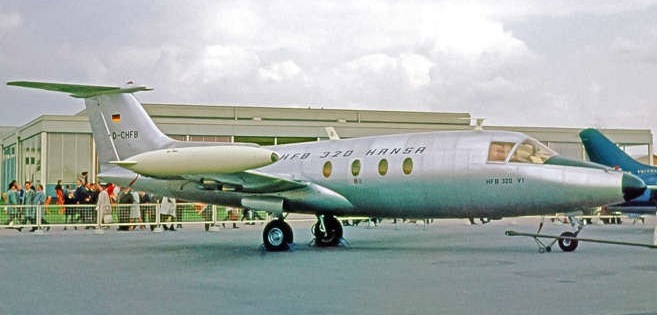
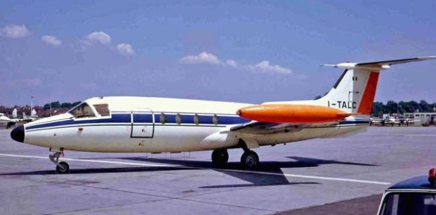
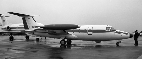
Hamburger HFB.320 Hansa Article
The Hansa 320 is identified by the 15-degree forward sweep of the wings. In addition to providing the low-speed flying characteristics desired, the adoption of forward sweep enabled the wing to be mid mounted, this position permitting the use of a fuselage of optimum diameter (81 in). A mid wing layout is impractical with conventional aft swept wings, as it involves the main spar passing through the cabin. On the HFB 320 Hansa Jet, the cabin is forward of the main spar.
The Hansa Jet prototype D-CHFB first flew on 21st April 1964, for 73 minutes. The wing provided the flying characteristics hoped for. Control during the approach to, and in, the stall was excellent. During trials the aircraft was held in a full stall with an indicated angle of attack of 19 deg., and banked with the normal application of aileron. Warning of stall is consistent and readily evident.
Production of the Hansa was initiated by Hamburger Flugzeugbau and carried the name of Messerschmitt- Bolkow-Blohm (MBB) when the two German aircraft companies merged in 1969. The first production Hansa Jet flew on February 2, 1966, and received FAA certification on April 7, 1967. However, the problem of providing the exceptional wing torsional stiffness required, without excessive weight penalty, was not entirely over¬come. To prevent the main landing gear bay breaking into the vital lower wing skin, the legs are stowed in fuselage fairings, ahead of the forward wing root. This results in a narrow track. To keep the air flowing over the heavily loaded inboard end of the wing, short span slats are fitted to the inner section of the wing. Without such a device, a forward swept wing will generate less lift than one swept aft.
A US test pilot, Loren W. Davis, was engaged for the initial flight programme.
In the second part of 1968, after three HFB-320 were ordered for the RLS, the Hansajet became well known at Groningen-Eelde. HFB directed a number of brand-new HFB-320 Hansa jets to Groningen Airport Eelde in the Netherlands for test flying and training.
In spite of the good low speed qualities, the Hansa Jet did not initiate a business jet fashion. The theoretical aerodynamic advantages were in practice too deeply eroded by the increased wing weight, its complexity and cost.
A parachute brake in the tail is used for short or icy runways. About 50 were built in executive, cargo and quick-change versions.
Hamburger Flugzeugbau HFB 320 Hansa Jet
Engine : 2 x General Electric CJ610-1, 12704 N / 1295 kp
Length : 54.462 ft / 16.6 m
Height : 15.748 ft / 4.8 m
Wing span : 47.572 ft / 14.5 m
Max take off weight : 18742.5 lb / 8500.0 kg
Max. speed : 486 kts / 900 kph
Service ceiling : 38058 ft / 11600 m
Range : 1253 nm / 2320 km
Crew : 2+12
Engines two 3,108-lb. s.t. General Electric turbojets.
Gross wt. 20,280 lb.
Empty wt. 11,960 lb.
Fuel capacity 1,099 USG.
Top speed 513 mph.
Cruise 420 mph.
Stall 111 mph.
Initial climb rate 4,250 fpm.
Range 1,472 miles.
Ceiling 40,000 ft.
Takeoff distance (50′) 2,740 ft.
Landing distance (50′) 4,429 ft.
Seats 15.
Formed originally by Blohm und Voss in 1933. Aircraft production resumed 1956 with license manufacture of Nord Noratlas for Luftwaffe. Co-operated in license-production of Luftwaffe Lockheed F-104Gs and assisted with design work of Fokker F28 and Dornier Do 31E V/STOL project. HFB 320 Hansa Jet 6/11 -seat business jet first flew 1964.
Merged with Messerschmitt-Bolkow in 1969 to form MBB.
The Halton Man Powered Aircraft Group at No.1 School of Technical Training, RAF Halton, built the Jupiter man-powered aircraft using the remains of the Woodford MPAG’s machine.
It retained much of the Woodford aircraft’s general appearance.
Jupiter first flew from RAF Benson on 19 March 1972. On 29 June 1972 managed to fly 1171 yards.

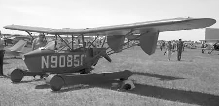
The Aero Car N9085C was built in 1959 by Joseph L. Halsmer of Lafayette, Indiana was one of the numerous attempts at building a roadable aircraft.
Airline captain Helsmer built this machine over a two-year period for $2,300. N9085C was later converted into single-engine Aero Car 3. Halsmer also built a high-wing two-seater with a uni-twin arrangement of two 65hp engines driving two counter-rotating props, registered N12043.

The Aero Car was a high-wing monoplane with two engines in a tractor-pusher configuration, a tri-cycle gear and tail booms. Helsmer built this machine over a two-year period, and later converted into the single-engine pusher Aero Car 3 presented in 1963 powered by a Continental C-85-12 engine.
Joseph L. Halsmer of Lafayette, Indiana was one of the numerous attempts at building a roadable aircraft,
Halsmer was a Seaboard World Airlines captain and father of 11 children, who built various Aero Car circa 1959.
Halsmer built a high-wing two-seater N12043 (possibly the Aero Car 2) with a uni-twin arrangement of two 65 hp engines driving two counter-rotating props.
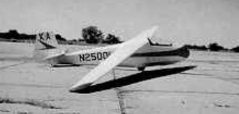
The Cherokee II, designed by Stanley Hall, was introduced in 1956 specifically for amateur construction from plans. The entire wood airframe is covered in fabric. Upper surface spoilers control the glidepath, and the landing gear is fixed. Many examples vary in detail. L/D max. 23. The design was further developed by several builders including the Cherokee RM by Terry Miller and John Ree with a 13.4 m. / 44 ft. span wing with NACA 64(3)-618 airfoil which increased L/D max. to about 28, and the 15 m. Leonard Annebula which has Prue type trailling edge airbrakes and a claimed L/D max. of 31.
Plans are available only as secondhand now.
A Cherokee RM belongs to the National Soaring Museum.
The Flagor/Hall powered version of a Hall Cherokee II single seater sailplane was produced by Mr Ken Flaglor of Northbrook, Illinois, who fitted the Cherokee II he had built from plans some years before with two 10hp West Bend Model 82001-1 and Model 82002-1 Power Bee go-kart engines. These were mounted on pylons each side of the fuselage under the wings, and drove opposite-rotating Troyer wooden pusher propellers of 2 ft 0 in diameter; the fuel capacity was 2 US gallons. The first flight of Mr Flaglor’s powered Cherokee II, registered N12042, was made in June 1964. The basic Cherokee II is a shoulder wing single seater of conventional wood and fabric construction, plans of which were marketed by its designer, Mr Stanley A. Hall.
Wing span: 12.19m / 40ft
Wing area: 11.61sq.m / 125sq.ft
Empty Weight: 154kg / 340lb
Payload: 86kg / 190lb
Gross Weight: 240kg / 530lb
Wing Load: 20.3kg/sq.m / 4.23lb/sq.ft
Aspect ratio: 12.8
Airfoil: Go 549
MinSink: 0.82 m/s / 2.7 fps / 1.59 kt
No. of Seats: 1
L/DMax: 23 @ 74 kph / 36 kt / 46 mph
No. Built: 80
Structure: wood/fabric; 2-spar wing
Flagor/Hall Cherokee II
Engines: 2 x 10hp West Bend Model 82001-1 and Model 82002-1 Power Bee
Propellers: 2 x Troyer wooden 2 ft 0 in diameter
Span: 40 ft 0 in
Length: 21 ft 6 in
Wing area: 125 sqft
Aspect ratio: 12.8
Empty weight: 375 lb
Max weight: 580 1b
Fuel capacity: 2 US gallons
Max level speed: 72 mph (power on)
Cruising speed: 60 mph (power on)
Min sinking speed: 4 ft/sec (unpowered)
Best glide ratio: 16.5:1 at4 5mph (unpowered)
Take-off run: 900 ft
Endurance: 1 hour (power on)
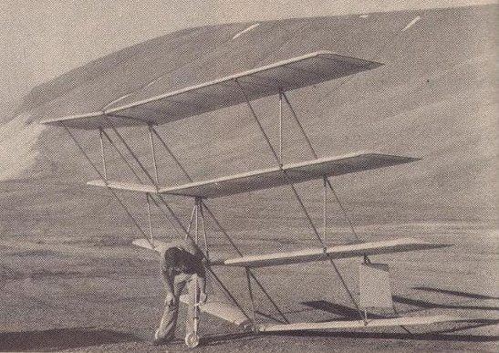
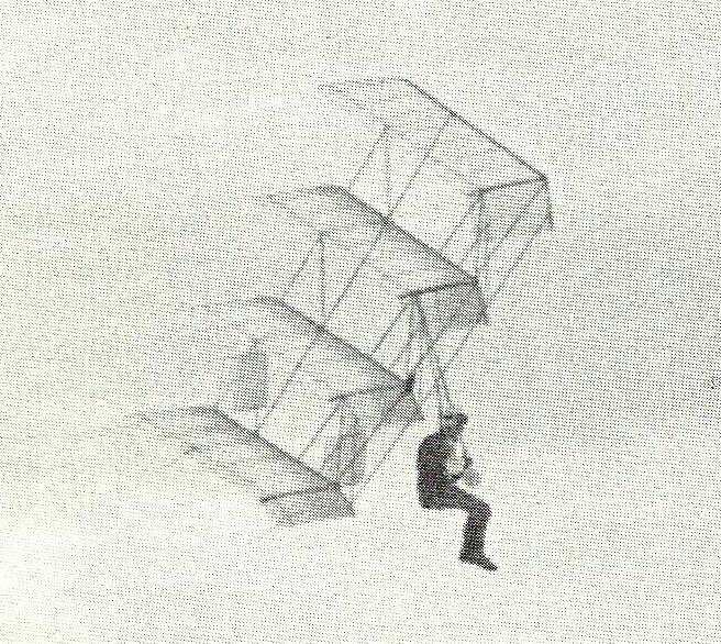
In the late 1970s, an American hang-glider enthusiast called Larry Hall used the Sellers Quadruplane as the basis for his own hang-glider design. The design goal was to fly a human pilot using super-efficient RC sailplane wings, with enough wings (stacked) to keep airspeeds low and provide good soaring ability.
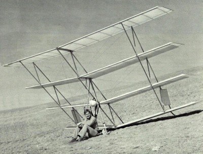
Each wing panel of the QuadraPlane was separate, so setup/teardown always looked like a yard sale in progress. Each wing panel had 1.5 degrees more positive incidence than the wing below, for a total of 4.5 degrees between the top and bottom wings. This was done to provide an automatic dive recovery system, even though no reflexed airfoils were used. This increasing wing incidence, and the forward stagger of the upper wings, assured that they made more lift than the lower (rearward) wings, in a dive, and that would bring the glider back to normal flight modes, very quickly. Back in the day, a hang glider with an automatic dive recovery system was a rare bird.
The QuadraPlane had no tail surfaces. Steering was done by cables to the tip drag rudders, and they were very effective. The short wingspan meant that the QuadraPlane could turn in very small circles, and do it very well.
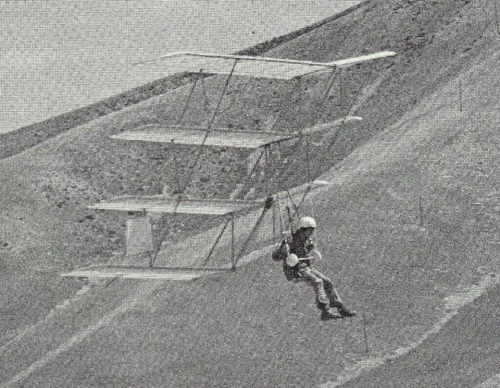
The pilot sat in a “swing seat” harness, with the pilot’s waist just below the triangle control-bar (where the wheels are). The glider was foot-launched, like any hang glider. In flight, the pilot had an amazing view, being far in front of the lower wings.
The QuadraPlane is now stored in the rafters of a hangar at the Morgan, Utah airstrip.
Spans from top:
20′ 10″; 19′ 10″; 18′ 10″; 17′ 10″
Chord 2′ 6″
Wing Area 185 sq.ft
Dihedral 6 degrees
Weight Approx. 65 lbs.
Stagger 45 degrees
Sweep 10 degrees
Airfoil Similar to Icarus II without reflex
Rudder Area 2.36 sq.ft each
Overall height 10 ft
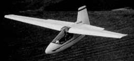
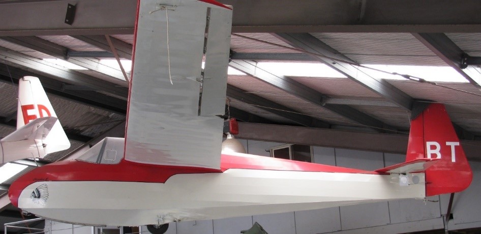
The “Minibat” ultralight single-seater glider was designed by Larry Haig of Muskegan, Michigan, over a three-month period at a cost of $3,500, and made its first flight on March 11, 1979. The Minibat had a cantilever, swept forward wing and used a reflex airfoil. It was constructed of Kevlar, carbon fibres and foam sandwich with glass fibre covering. The fuselage was made up of two halves joined by the metallic structure which formed the pilot’s seat. Wings were demountable in the same way as a conventional glider, and a peculiarity of this machine was that the two ailerons could be raised together to act as spoilers. Extended wing tips were also available, increasing span to 10 meters.
The Minibat was available as fast-build kits for the homebuilder, assembly was said to require only 5 – 10 days using moulded parts. A powered version was planned, using a 3 hp chain saw sustainer engine mounted behind the cockpit and driving a pusher propeller mounted in a slot between the fin and rudder. The Minibat was not a self-launching design but the engine was intended, after launch by auto-tow, winch or bungee, to provide a positive rate of climb.
By January 1982, four Minibats had already had accidents during take-off. It was concluded that this machine should not be made available to just anybody, as it was initially expected. It seems that the airfoil was the major cause for the bad handling characteristics. But yet the Minibat was a very interesting concept of a very light and efficient “minimum” glider.
Minibat
Wing span: 7.62m / 25ft
Length: 2.84 m / 9.33 ft
Height: 5 ft
Wing area: 6.04 sq.m / 64.5sq.ft
Fin area: 7.5 sq.ft
Empty Weight: 50kg / 110lb
Payload: 98kg / 215lb
Gross Weight: 147kg / 325lb
Wing Load: 24.5kg/sq.m / 5lb/sq.ft
Load limit: ±6 G’s
L/DMax: 23 at 55 mph
Stall: 39mph
Min Sink @ 43 mph: 0.91 m/s / 3 fps / 1.78 kt
No. of Seats: 1
Structure: foam and fibreglass
Aspect ratio: 9.6
Max. Smooth air speed: 126 mph
Maneuvering: 88 mph
Flutter Tested To: 140mph
Landing Gear: Fixed
Engine: 3 hp
Fuel Capacity: 2 litre
Endurance: 1 hr
Propeller: 20×10 fixed pitch.
Rate of Climb: 50-100fpm
Minibat Extended Tip
Wing span: 10m / 32.7ft
Wing area: 7.11sq.m / 76.5sq.ft
Empty Weight: 59kg / 130lb
Payload: 100kg / 220lb
Gross Weight: 159kg / 350lb
Wing Load: 22.36kg/sq.m / 4.5lb/sq.ft
Aspect ratio: 14
Structure: foam and fiberglass
L/D Max: 30:1
Minimum Sink: 2.3 ft/sec
V-Stall: 23 mph
The prototype of this tandem two-seat training sailplane flew on September 10, 1956 and at least eight more were flying by 1961.
Construction is similar to that of the H-22B-3.
Span: 43 ft 2 in
Length: 23 ft 4 in
Wing area: 185 sq.ft
Gross weight: 838 lb
Empty weight: 463 lb
Max L/D: 18 at 42.5 mph
Min sink: 3.6 ft/min at 38.5 mph
