USA
Based at Concord, California, produced the D.1. agricultural aircraft in 1959 and the F-2 Baby ultralight single-seat biplane in 1960.
Post WW2
Larsen LN-11
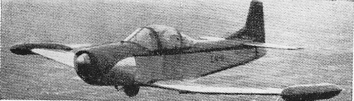
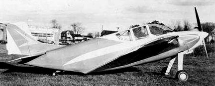
Designed by Carl Larsen in Norway in the 1950s, the LN-11 is a single seat, all-metal sport plane with retractable undercarriage.
Engine: Continental C90, 90 hp
Span: 22 ft
Length: 20 ft
AUW: 900 lb
Max speed: 165 mph
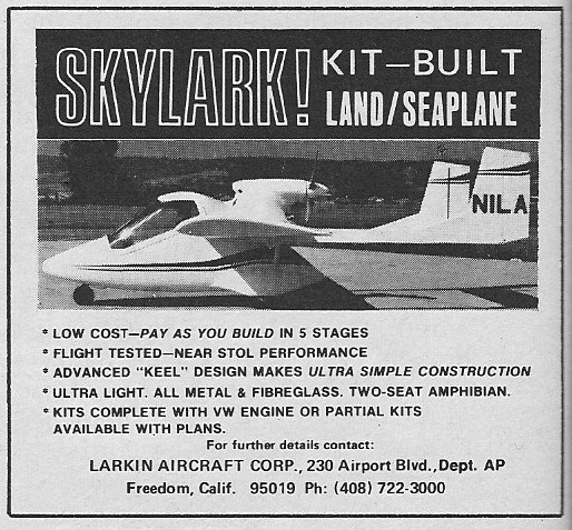
Larkin Skylark KC-3
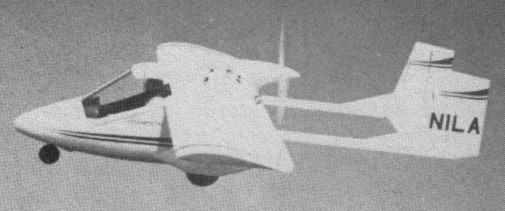
The Larkin KC-3 Skylark was a single-engine amphibious two-seater homebuilt aircraft, a pusher-style design with a single 100 hp Volkswagen air-cooled engine above and behind the fully enclosed cockpit. The booms are at¬tached to the wings and connected at the rear, between twin vertical stabilizers, by one single-elevator surface. One unique feature of the airplane’s structure is the use of a square tubular aluminum keel which is responsible for the loads from the landing gear and the main fuselage. The cockpit seats two occupants in side-by-side configuration, with a large Plexiglas canopy curving around both occupants. The landing gear is a tricycle arrangement with the nose gear positioned at the foremost point of the nose and the two main gear semi-recessed into teardrop-shaped fairings on the lower sides. For amphibious operations, there is an optional V-shaped lower hull of fiberglass which can be added.
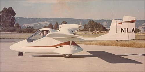
The Skylark KC-3 first flew in 1972 and was registered N1LA.
My father, Tony Austin, worked for Larkin Aircraft in the late 1960s-early ’70s. He collaborated on the engineering and fabrication of the fuselage and other structural components of the one prototype. I had opportunity as a boy to witness the Skylark’s construction and first flight, and have sat in the actual aircraft. I never flew in it as it was only ever piloted by the designer, Keith Larkin himself, to my knowledge.
Thad Austin
Engine 65-hp Volkswagen.
Wingspan 26’6”
Length 19’6”
Gross Wt. 1246 lb
Empty Wt. 790 lb
Fuel capacity 17 USG
Top speed 115 mph
Cruise 105 mph.
Stall 42 mph
Climb rate 550 fpm
Ceiling 12,000 ft
Takeoff run 600 ft
Landing roll 400 ft
Range 525 miles
Seats: 2
Lanzalone Aulanz
This Argentine single-seater motor glider was designed and is being built by Senor Augusto Lanzalone of Rosario in Santa Fe province, who has also formed the Asociacion Argentina de Constructores de Aviones Experimentales – Avex for aircraft like the Aulanz. Not only has Senor Lanzalone designed and built the engine for it – a 30hp Lanzalone two-cylinder two-stroke inverted inline motor of 700cc – he has evolved his own special alloy for the construction of the airframe. This is known as Alcusing, and consists of aluminium with portions of copper, nickel, magnesium, silicon and chrome; the two-blade variable pitch propeller is also made of this material.
The Aulanz is a conventional low-wing monoplane of semi-monocoque Alcusing structure, with the engine in the nose and a retractable rubber-sprung monowheel under the wing leading edge, plus a tailskid. The total fuel capacity is 20 litres (4.4 Imp gallons). By the spring of 1973 the prototype’s fuselage and tail unit were completed, and construction of the remainder had been proceeding slowly.
Span: 40 ft 8.25 in
Length: 17 ft 8.5 in
Height: 6 ft 1.75 in
Wing area: 125.9 sqft
Aspect ratio: 13.1
Max weight: 617 lb
Lanier 443 Paraplane
The 1949 443 Paraplane was apparently a larger, possibly high-wing, reconstruction of the Lanier Paraplane with a 180hp Lycoming O-320, again registered N9060H. The project was abandoned circa 1955 after failing to attract a market.
Engine: 180hp Lycoming O-320
Max speed: 171 mph
Stall: 30 mph
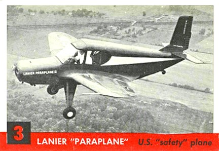
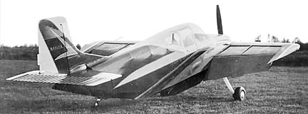
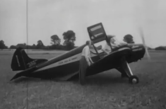
Lanier 120 Paraplane I / Paraplane II
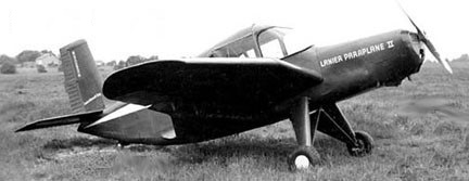
The 1949 120 Paraplane I N9060H test-bed was used by Office of Naval Research in STOL evaluation. First flown by Leo Riley, the Paraplane featured an inverted “Vacucell” gull-wing with an air scoop below and vacuum-slots on top—operated by a hand-crank in the cockpit—enabled slow flight at 19mph, take-off in 100′, a 30° climb angle and 40° descent angle, and was spin- and stall-proof.
A modified Paraplane II showed up in 1949 with a 22’6″ wing and was capable of nearly hovering.
Engine: Continental A-90, 90hp
Wingspan: 20’5″
Length: 22’0″
Useful load (prototype): 455 lb
Max speed: 120 mph
Cruse speed: 30-120 mph
Stall: 28 mph
Seats: 1
Lanier 110 Paraplane Commuter PL-8
The 1958 110 Paraplane Commuter PL-8 N4157A was built for controllable slow-flight at 20-25 mph and take-off and land in 60 ft. The Paraplane Commuter 110 or 110 Paraplane Commuter PL-8 was one of the last designs stemming from Edward H. Lanier’s 1930s patents, and aircraft incorporating apertures in the upper surfaces, which claimed to give benefits in safety, lift and STOL ability.
In the early 1930s Edward H. Lanier published six US patents concerned with increased aircraft lift and stability, minimising the stall, sideslip and spin. This was to be achieved through vacuum chamber (“Vacua-cells”), initially in the upper fuselage but later in the upper wing, where the reduced pressure established by airflow over a curved surface would act on the lower surface inside the cell, providing lift. The second patent suggests that the cell should contain angled spanwise slats to prevent air entering them at low speeds and that these should be adjustable so that the cells could be closed when required. The earlier patents stress stability improvements; claims of enhanced lift begin with the fourth patent. Five Lanier Vacuaplanes were built in the 1930s, followed by three Paraplanes from about 1948, before the Paraplane Commuter 110 which first flew in 1958.

The Commuter 110 had a wing area of 111 sq ft (10.3 sq.m), large for its 20 ft 7 in (6.28 m) span, and controllable air entrance slots (“Vacua-Jets”) under the lower surface near its leading edge, passing air to the upper surface for boundary layer control. Other details of the upper surface are scarce but photographs appear to show rear hinged, single-piece slats over Vacua-cells as well as narrow open channels next to the fuselage in the very long wing root fairings. Structurally, the cantilever mid wing had strongly cranked inner sections and was tapered in plan with elliptical wing tips. The outer panels carried control surfaces which operated differentially as ailerons and together as flaps. In addition, there were split flaps under the trailing edges of the wing roots.
The fuselage of the Commuter 110 was a semi-monocoque structure, flat-sided and tapering upwards markedly aft of the wing roots to the tail. The pilot sat in an enclosed cockpit long enough to contain a second seat in tandem, the canopy merging into the upper fuselage at its rear. One source describes the Commuter as a single seat aircraft, another as a one or two seater. The Commuter’s empennage was conventional, with straight edged, square-tipped horizontal surfaces and a straight edged rudder with a trim tab mounted on a narrow fin with a fillet to the fuselage. There was a 150 hp (112 kW) Lycoming O-320 air-cooled flat-four engine in the nose, driving a two-blade propeller. It had a fixed conventional undercarriage with cantilever main legs mounted on the lower fuselage and a short-legged tailwheel on the sloping underside, about halfway between the edges of the root fairings and the extreme tail. The mainwheels had brakes and the tailwheel was steerable.
The Commuter made its first flight in 1958. Described as an STOL aircraft, it had respectable takeoff and landing characteristics, though no records comparing performance with open and closed Vacua-cells seems to have survived. A more recent study suggests the known figures were not exceptional given its thick wing, weight and power. Perhaps more significantly, the authors’ computed aerodynamic investigations of open or slatted upper wing surfaces, though made at very low Reynolds numbers, show no evidence that Vacua-cells enhanced wing performance.
The name, Paraplane, fell out of copyright and was adopted for powered parachutes c.2000.
Lanier Paraplane Commuter 110
Engine: Lycoming O-320, 150hp
Propeller: 2-bladed McCauley, 6 ft 4 in (1.93 m) diameter metal, fixed pitch
Wingspan: 20’7″ (6.28 m)
Wing area: 111.0 sq ft (10.31 m2)
Aspect ratio: 3.8
Length: 21’5″ (6.53 m)
Empty weight: 780 lb (354 kg)
Gross weight: 1,280 lb (581 kg) normal
Max takeoff weight: 1,400 lb (635 kg) ferrying
Fuel capacity: 24 US gal (20 Imp gal; 91 L) normal, in wing tanks; 44 US gal (37 Imp gal; 166 L) for ferrying
Max speed: 165 mph (266 km/h, 143 kn)
Cruise speed: 151 mph (243 km/h, 131 kn)
Stall: 30 mph
Range: 625 mi (1,006 km, 543 nmi) normal, with 45 min res
Service ceiling: 23,000 ft (7,000 m)
Rate of climb: 1,500 ft/min (7.6 m/s)
Take-off and landing speeds: less than 30 mph (48 km/h)
Take-off and landing runs: 60 ft (18 m)
Seats: 1-2
Langley Aircraft Corp
Established in 1940 as Langley Aircraft Corp (pres: Caleb S Bragg). Langley Aircraft Corporation was based in Port Washington, NY, with director Martin Jensen and Arthur Draper.
In 1942 the company was acquired by Andover-Kent Aviation Co (pres: J J Brooks), New Brunswick NJ, but WW2 curtailed activity. After the company built the first airplane, two or three cars were released in 1942 under the license of “Andover-Kent Aviation Company”.
1947: Langley Aviation Co, New York NY.
Langhurst JU87-B2 Stuka
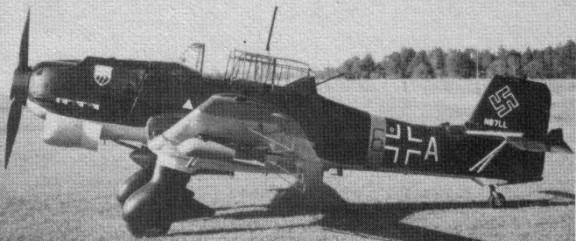
Like the original, the Langhurst replica Stuka is a two-place aircraft with a single control from the front seat. The rear seat faces the tail. The replica is completely of metal construction. Basically, it is a com¬posite. It has an inner steel-tube frame and an aluminum skin. Because the original rib type was unknown, Langhurst utilized the NACA 2415, which looks very much like the original.
The 7/10 Stuka is actually a full-sized airplane by most homebuilt standards. It has a full electrical system, full hydraulic system and complete fuel manage¬ment system. The landing gear and tailwheel units are standard from a PT-19.
Registered N87LL, the Stuka first flew on 19 July 1978.
The aircraft is now on loan to the San Diego Aerospace Museum.
Engine: 220-hp Lycoming GO-435
Wingspan: 32’6”
Length: 24’0″
MTOW: 2275 lb
Empty weight: 1680 lb
Top speed: 137 mph
Cruise: 120 mph
Stall: 62 mph
Climb rate: 1100 fpm
Lang Sport
Circa 1968 Frank Lang of Lockport IL. Built the single-place open-cockpit, low-wing monoplane Sport, powered by a Menasco.
