Victor W Pagé (nee: Pager) & Oliver Light, Farmingdale NY.
In 1909 Victor W Pagé & Oliver Light built a biplane. It was designed by the founder of Pagé aviation mechanic training schools, Victor W Pagé, and author of several popular technical aviation books c.1918-35.
The LUSAC-21 (LUSAC = LePere US Army Combat) of 1919 was LUSAC-11 refitted with the 420hp Bugatti 16 engine. One prototype was converted: AS40023.
Thirty LUSAC-11s with Liberty engines and three LUSAC-21 s with Bugatti engines were built, but contracts for quantity production were cancelled at end of First World War.
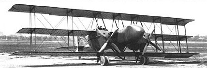
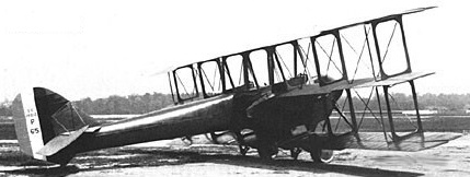
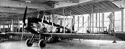
The 1919 LUSAO-11 (LUSAC = LePere US Army Observation) was a high-altitude long-range three seat open cockpit triplane observation aircraft for the Signal Corps.
Packard-LePere LUSAO 11 SC40012
Only one prototype was built, SC40012.
Engines: 2 x Liberty 12, 400hp Props: four-blade Wingspan: 54’6″ Length: 38’2 Useful load: 3122 lb Mas speed: 112 mph Cruise speed: 106 mph Stall: 60 mph Range: 475 m Ceiling: 17,300′
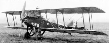
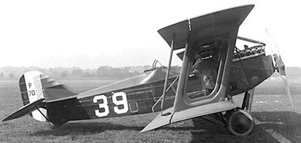
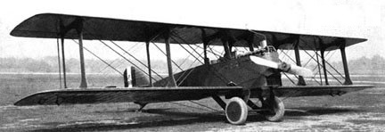
Captain Le Pere of the French Aviation mission to the USA, and Dwight Huntington designed a two-seat fighter, the LUSAC-11 (Le Pere United States Army Combat), which was built by the Packard Motor Car Company in 1918.
First flying in August 1918 piloted by Lt de Marmier, the LUSAC 11 (LUSAC = LePere US Army Combat) featured a plywood fuselage and box-type wing struts. It was the first US aircraft with a turbo-supercharger, and first to leave a vapor trail, on 27 February 1920.
Packard-LePere LUSAC 11
Two prototypes and 24 production LUSAC-11s with Liberty engines [AS40013/40023, AS42129/42142, AS42151] and three LUSAC-21s with Bugatti engines were built, but contracts for nearly 3,500 were cancelled at end of First World War.
AS40021 was modified as a single seat LUSAGH-11 with longer wings and a canopied cockpit at McCook Field. LUSAGH = LePere US Army Ground Harassment.
USA Captain Le Pere of the French Aviation mission to the U.S.A. designed a two-seat fighter, the LUSAC-11 (Le Pere United States Army Combat), which was built by the Packard Motor Car Company in 1918. Thirty LUSAC-11 s with Liberty engines and three LUSAC-21 s with Bugatti engines were built, but contracts for quantity production were cancelled at end of First World War.
Circa 1919, the two place open cockpit biplane Packard A was Packard’s entry, featuring a self-starter, was planned for a civil market that failed to develop.
Only one was built, registered cn 01, N707.
A two place open cockpit biplane with a 200hp Packard-Liberty 8 found in the registers might be this ship, but it was not specified as actually a Packard Co product. The registry shows several private owners in Mt Clemens and Saginaw.
In 1943, Packard leased a government-owned manufacturing plant located on the outskirts of Toledo, Ohio. The plant was previously operated by the defunct Aviation Corporation. Packard used the leased plant to manufacture parts for the Rolls-Royce Merlin engine, and referred to it as its Toledo Division. In the early-summer of 1944, the Army Air Force Material Command contracted with Packard to carry out “advanced aircraft engine development” on both the Merlin and gas-turbine engines. To oversee the new project, Packard hired Allison Engine Company’s Robert M. Williams as their chief design engineer at the Toledo facility in July of that year. In October 1946 Williams and Dr. George F. Wislicenus, one of the engineers working under him, discussed ways of improving the efficiency of turbojet engines. They came up with an engine design which they called a “ducted fan”. The resulting engine was Packard’s model PT-205, with the military designation Packard XJ49-V-1 turbofan engine.
The XJ49 design was a break from conventional design practices of the time. Most turbojet engines then used one centrifugal compressor, one turbine wheel and multiple combustion chambers that resembled long cylinders arranged in a conical pattern. The XJ49 design had a two-stage compressor made up of an axial-flow supersonic compressor at the engine intake, driven by the second power turbine wheel, followed by a spirally-shaped mixed flow compressor, driven by the first turbine wheel, giving an over-all compression ratio of 6:1.
Power from the annular combustion chamber exhaust drives the complex two-stage turbine. The discharge flow from the first turbine stage drives an independent two-stage turbine. The blades of the last stage of the second turbine are extended beyond the engine core to form a supersonic fan that provides air flow around the engine core for additional thrust and further combustion. Supplementary burning (reheat or afterburning) between the two turbines and in the tailpipe can also be used for additional thrust.
The period between drawing up the basic design theory and a having a complete engine ready to make its first run on a test stand was unusually short, as Packard started testing the first (and only) XJ49 in November 1948. When the testing was complete, the XJ49 proved itself to be the most powerful jet engine in operation at the time.
On September 16, 1959 the United States Air Force released the XJ49 engine to the National Air Museum (now the National Air and Space Museum), and is now in storage at their Silver Hill, Maryland facility.
Specifications: XJ49-V-1 Type: Ducted Fan (Turbofan) Compressor: Compound: Two-stage compressor (an axial-flow supersonic 1st stage followed by a mixed flow second stage) Combustors: Annular Turbine: Compound: The gas discharge from the first stage turbine drives the following two-stage turbine. The blades of the last stage of the second turbine section extend outside of the engine core to form a supersonic bypass fan. Maximum thrust: Take-off: 12,000 lb, military: 11,000 lb, normal: 10,000 lb, cruising: 2,560 lb at 35,000 ft. Overall pressure ratio: Over-all pressure ratio of 6:1
In 1943, Packard leased a government-owned manufacturing plant located on the outskirts of Toledo, Ohio. The plant was previously operated by the defunct Aviation Corporation. Packard used the leased plant to manufacture parts for the Rolls-Royce Merlin engine, and referred to it as its Toledo Division. In the early-summer of 1944, the Army Air Force Material Command contracted with Packard to carry out “advanced aircraft engine development” on both the Merlin and gas-turbine engines. To oversee the new project, Packard hired Allison Engine Company’s Robert M. Williams as their chief design engineer at the Toledo facility in July of that year. In early 1945 the Power Plant Lab at Wright Field asked Packard to take on a research project to develop an expendable jet engine of 4,000 pounds thrust weighing no more than 1,000 pounds. Design work for the engine designated as the Packard XJ41 began in May 1945.
After studying existing turbojet engines it was decided to design an engine which would be a significant advancement over conventional turbo-jet engines, have a low manufacturing cost, minimum use of strategic materials and be a light-weight design.
The Packard XJ41 met those requirements with a combination of a mixed flow compressor, a light weight annular combustion chamber and hollow turbine blades for both rotor and stator. The engine’s most outstanding design characteristic was the use of an air inlet that operated at supersonic speed that produced more thrust per pound of weight than designs using low velocity inlet air. The XJ41 weighed 1,100 pounds and produced 4,000 pounds of thrust, where the GE J33 weighed 1,820 pounds at the same thrust. The engine was completed and operating on a test stand on January 8, 1946.
Packard’s investment for production of the new turbojet engine design was extensive. By the end of 1946 the installation of fabrication and testing equipment was valued at $10,000,000. In addition, flight testing, shop and hangar facilities at Willow Run, Michigan was valued at $1,000,000, and an additional $3,500,000 in laboratory and testing equipment was installed by spring of 1947.
Serial numbers V-500001 to V-500007 were allocated indicating that at least seven engines were built. Development continued on the engine over three years, with Packard assigning model numbers PT-103 and PT-104 to military engine designations XJ41 serial number V-500001 and XJ41 serial number V-500003. A design study for an engine suitable for high acceleration, such as a catapult launched take-off, was assigned model number PT-106 in February 1947. Between September 1947 and July 1948 an XJ41 engine attached to a North American B-25J Mitchell bomber was flight-tested several times.
Development of the XJ41 stopped when Packard engineers came up with a radical redesign that differed so much that military model XJ49 was assigned. All work on the earlier design was terminated and funding was transferred to the new design.
Specifications: XJ41-V-500003 Dry weight: 1,100 lb (499 kg) Compressor: single-stage Mixed-flow (combined axial and centrifugal) Combustors: annular combustion chamber Turbine: single stage hollow blades Fuel type: Aviation Kerosene jet fuel Oil system: pressure fed scavenged spray system with dry sump Maximum thrust: 4,000 lbf (18 kN) Thrust-to-weight ratio: 3.64
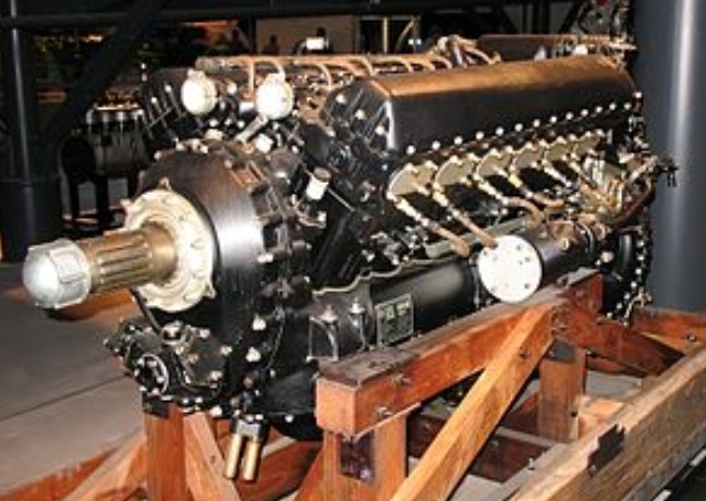
In June 1940, Henry Ford had offered to manufacture 1,000 aircraft a day if the government would let him do it his way, and during a discussion with Secretary of the Treasury Henry Morgenthau Jr. regarding what the Ford company might produce, Ford’s son Edsel tentatively agreed to make 6,000 Rolls-Royce liquid-cooled engines for Great Britain and 3,000 for the U.S. However, at the beginning of July, Henry Ford stated that he would manufacture only for defense, not for Britain, and the entire deal was declared off. Members of the Defense Advisory Commission subsequently began negotiations with other manufacturers in an effort to place the $130,000,000 Rolls-Royce order, and Packard Motor Car Company was eventually chosen because the engine’s British parent company was impressed by its high-quality engineering. Agreement was reached in September 1940, and the first Packard-built engine, designated V-1650-1, ran in August 1941.
The first American version of the Merlin was the Packard Merlin 28 (Mark XX), designated the V-1650-1 by the American military. This engine used a single-stage, two-speed supercharger. The two-speed gearing was – as well as for the “R-R” Merlins – from a French Farman patent license. As the Merlin 28, it was used for the Avro Lancaster bomber. The USAAF V-1650-1 version of this engine was used in the Curtiss P-40Fs. The initial Packard modifications to this engine changed the main crankshaft bearings from a copper lead alloy to a silver lead combination and featured indium plating. This had been developed by General Motors’ Pontiac Division to prevent corrosion which was possible with lubricating oils that were used at that time. The bearing coating also improved break-in and load-carrying ability of the surface.
The real improvement Packard incorporated into the Merlin was adopting the Wright supercharger drive quill. This modification was designated the V-1650-3 and became known as the “high altitude” Merlin destined for the P-51. The two-speed, two-stage supercharger section of the V-1650-3 featured two separate impellers on the same shaft that were normally driven through a gear train at a ratio of 6.391:1. A hydraulic gear change arrangement of oil operated clutches could be engaged by an electric solenoid to increase this ratio to 8.095:1 in high speed blower position.
The high speed gear ratio of the impellers was not as high as the ratio used in the Allison, but impeller speed is not the only factor that determines engine performance, which is also a function of the size and pitch of the impeller blades. The gear-driven supercharger is a parasitic accessory; therefore, impeller gearing and blade profiles are carefully designed for maximum power at altitude without compromise of available power at the critical take off stage of flight. The double staging of the compressed fuel/air mixture provided the boost pressure through a diffuser to the intake manifolds that increased the critical altitude of the power plant.
The ability of the supercharger to maintain a sea level atmosphere in the induction system to the cylinders allowed the Packard Merlin to develop more than 1,270 horsepower (950 kW) at altitudes beyond 30,000 feet (9,100 m). The two-stage impeller created extreme heating of the fuel/air mixture during the compression process and to prevent detonation of the compressed charge, it was necessary to cool the mixture prior to entry into the cylinders. The cooling was accomplished in an intercooler passage cast into the wheel case housing between the first and second stage impellers.
Ethylene glycol coolant was circulated by a pump through this passage to carry off the excess heat generated by the impellers. Without the intercooler the temperature of the charge could be as high as 400 °F (204 °C). The intercooler in itself was not adequate to deal with the high temperature and an additional cooling fin and tube core was placed between the outlet of the blower and the induction manifold to the cylinders. This radiator was known as an aftercooler and served as a reservoir for the supercharger cooling system. The glycol mixture used for cooling was independent of the main engine cooling system and used a centrifugal pump driven by the engine to circulate the coolant through an aircraft radiator system at a maximum rate of 36 U.S. gallons (136 litres, 30 Imperial gallons) per minute, depending on engine rpm. This combined system reduced the charge temperature to suitable levels.
Throttle valves in the updraft carburettor throat were controlled by an automatic boost control through the throttle linkage to maintain the selected manifold pressure with changes in altitude. The valves were only partially open during ground and low level operation to prevent overboosting of the engine. As air density decreases with increased altitude, the throttle valves were progressively opened in response to the reducing atmospheric pressure. This system provided full power within engine boost limitations up to the critical altitude of 26,000 feet (7,900 m).
It found its most famous application in the North American P-51 Mustang fighter, where it vastly improved that aircraft’s performance at altitude, transforming the Mustang into an outstanding fighter with the range and performance to escort heavy bombers over the European continent. By 1944, P-51B, P-51C and P-51D “Merlin” Mustangs were able to escort Allied heavy bombers in daylight all the way to Berlin and yet were still capable of combating German fighters attempting to intercept the bombers. By late 1944, the Allies had won air supremacy over the whole of Germany, and Germany’s defeat in World War II began to appear inevitable.
A total of 55,523 were built.
In the United States many war surplus engines and airframes were sold relatively cheaply – two of the most popular items were North American P-51 Mustangs and Packard V-1650 Merlin engines, several of which were “souped up” and modified for air racing in the Bendix Trophy, the Cleveland Air Races, and the Thompson Trophy.
Work continues on increasing the power output of the Merlin for the Unlimited Class racers at the Reno Air Races. Innovations, such as the use of Allison V-1710 connecting rods and the replacement of the intercooler with ADI (Anti-Detonate Injection) (50% Distilled Water and 50% Methanol), essentially the same idea as the Water Injection system used on Pratt & Whitney engines during World War II, have allowed great increases in power output. Many of the fastest Unlimited racers increase Merlin manifold pressures as high as 145 inHg (56.6 psi, 4.8 atm) to obtain the 3,800 horsepower, achieving Mustang speeds up to 490 mph.
Variants: V-1650-1: 1,390 hp (1,040 kW); Based on Merlin 28, used in P-40 Kittyhawk and Curtiss XP-60 fighters
V-1650-3: 1,280 hp (950 kW); Based on Merlin 63.
V-1650-5: 1,400 hp (1,000 kW); Experimental.
V-1650-7: 1,315 hp (981 kW); Similar to Merlin 66, primary powerplant of the P-51D Mustang.
V-1650-9: 1,380 hp (1,030 kW); 2,218 hp WEP with Water methanol injection.
V-1650-9A: 1,380 hp (1,030 kW);
V-1650-11: 1,380 hp (1,030 kW); Modified fuel system.
V-1650-21: 1,380 hp (1,030 kW); Opposite rotation for P-82 Twin Mustang
V-1650-23:
V-1650-25:
Applications: Avro Lancaster B Mk III/B Mk X Bell XP-63 Curtiss P-60 Curtiss P-40F/L Kittyhawk de Havilland Mosquito B Mk VII/B Mk 25 Hawker Hurricane Mk.X, XI, XII North American P-51 Mustang North American F-82 Twin Mustang Supermarine Spitfire Mk.XVI
Specifications: V-1650 Type: 12-cylinder supercharged liquid-cooled 60° “Vee” piston aircraft engine Bore: 5.4 in (137.2 mm) Stroke: 6 in (152.4 mm) Displacement: 1,649 cu.in (27.04 lt) Length: 88.7 in (2,253 mm) Width: 30.8 in (781 mm) Height: 40 in (1016 mm) Dry weight: 1,645 lb (746 kg) Valvetrain: Overhead camshaft-actuated, two intake and two exhaust valves per cylinder, sodium-cooled exhaust valve stems Supercharger: Two-speed two-stage, boost pressure automatically linked to the throttle, water-air aftercooler installed between the second stage and the engine. Fuel system: Twin-choke updraft carburettor with automatic mixture control Fuel type: 100 Octane, from mid 1944 100/150 Grade Aviation fuel Oil system: Dry sump with one pressure pump and two scavenge pumps. Cooling system: 70% water and 30% ethylene glycol coolant mixture, pressurized. Specific power: 0.95 hp/cu.in (43.3 kW/L) Compression ratio: 6:1 Power-to-weight ratio: 0.80 hp/lb (1.73 kW/kg) take-off; 1.21 hp/lb (2.69 kW/kg) 100/150 grade fuel/MS gear.