Polzien Blimp

About 1997, Marvin Polzien decided he wanted a homebuilt blimp. There were no quick-build kits for homebuilt blimps, set of plans and a kit of materials for a homebuilt blimp. Marvin, along with friends Dennis Riley and Louie Remondino, decided to design their own. Marvin subleased part of a large military hangar on the Ardmore airport, Oklahoma, and the work began, with other volunteers pitching in.

Their first model was a cylindrical bag of aluminized plastic attached along the bottom to a welded-aluminum truss structure. A simple platform suspended from the truss provided a place for the pilot to sit (in a plastic patio chair) and a place to mount the power unit (a hot-air balloon inflator fan). About that model, Marvin says, “It was a total disaster– the material we used was no good – it leaked like a sieve. We took it out of the hanger once and I made one tethered trip around the ramp, but that was all. Then we deflated it and put it away.”

Using lessons learned from the first model, the team designed the second model. He says, “We just made it up as we went– we didn’t know what we were doing. Our learning curve was pretty wide, so we’ve got a lot of junk lying around that didn’t work.”

The first step was to select a better material for the envelope. Helium is a small molecule that can sneak its way through most materials, so low permeability was a primary requirement. They selected a .009”-thick white heat-sealable polyester plastic with good tear resistance.

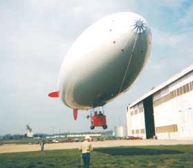
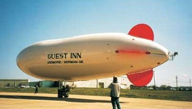
To achieve the desired buoyancy, they decided to make the envelope 82 feet long and 20 feet in diameter, tapered to form a streamlined nose and tail– an estimated 18,000 cu. ft. capacity. A two-place welded-aluminum “car” for a pilot and passenger would be supported from the bottom of the envelope, supported by a “catenary curtain” of suspension lines inside the balloon.
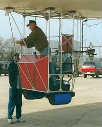
A 12-hp engine/propeller unit mounted on each side of the car would provide the main power. Each engine would be able to tilt up or down to vector thrust for climbing, cruising, or descending.

Pitch and yaw control would be provided by a third engine/propeller unit (24-hp) mounted on a gimbal at the extreme rear of the envelope and controlled from a control stick in the car. Fixed horizontal and vertical stabilizer panels would augment pitch and directional stability.
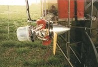
Inside the envelope would be two “balloonets” – smaller bags inside the large bag immediately forward and aft of the car– that could have air pumped in or out for trim control. Air would be provided from a compressor mounted on one of the engines.

A total of 13 gores of the 60” polyester would be required for the 20-ft diameter. In January 2002, the team laid out the gores on the hangar floor and cut them out. Then they began the monumental task of lapping and heat-sealing the gores together to form the envelope.

In February 2001, the envelope was fully sealed. After a preliminary filling with air (supplied ingeniously by a Shop Vac), the first filling with helium was an adventure. “We tried to fill from the middle first, but suddenly the helium all shifted to the front of the bag and up it went into the rafters! We were lucky we didn’t damage it. Now, we put sandbags across the envelope and fill from the back first. As it fills, the sandbags gradually roll toward the front,” Marvin said.

Of course, with the opportunity to fill with helium comes the necessity to empty it out now and then. But how does one keep from losing $1700 worth of helium? “Simple,” says Marvin, “We just built another storage bag bigger than the envelope and transferred it over!” But, how? “Shop Vac,” he says matter-of-factly. Marvin is a true innovator.

By March, the blimp had been taken outside for its first tethered flight. Finally, on August 3, 2002, the first free flight was accomplished. Watching video of the takeoff, Marvin said, “At that point, I didn’t know doodly about flying that blimp.”

After a short trip around the airport at about 200 feet at what appears to be about 30 mph, the video shows him approaching to land. He continued narrating, “About that time, I was asking myself how I was gonna land! I decided to rotate the engines down to pull me downward, but now I know I can just point the nose down a little to descend.”

Since then, Marvin has flown the blimp “five or six more times– I lose count.” On one flight he had an engine failure and, while trying to restart it, allowed the blimp to drift into some trees, punching a few holes in the envelope.
He has lost the lease on the big hangar and expects to be kicked out at any time. “I don’t know,” he says, “Sooner or later, I’ll have to deflate it, pack it up, and put it in my hangar.”

In December 2009 hundreds watched as a blimp piloted by 79-year-old Marvin Polzien flip flopped across the sky over Ardmore. He says he brought the blimp down near the freeway because a motor that helps steer the blimp failed. “I had three alternatives on how to land that thing. One was in the trees- that was not an option. Next one was in the median on the interstate, which is not good, and the third option which is to just take it up and let the wind blow me northwest of Ardmore,” Polzein said Thursday.

After the members of the FAA showed up wanting to see Polzien’s pilot’s license and medical certificate, which he couldn’t produce, his blimp could be grounded be for good. In order to operate an airship, it must first be certified with the FAA and its operator must have at least a private pilot’s license.

Also working against him is that fact this is not the first time he’s had to make an unscheduled landing. He crashed another home made blimp last May. That same blimp also floated away the next day and managed to make it all the way to North Texas with no one in it.
Polzien, Marvin

Marvin Polzien from Ardmore, Oklahoma, born 1930. Marvin’s interest in flying began early, in a little Iowa country school where he was fascinated with pictures of airplanes in the encyclopedia. His first flight was at age 12 when, defying his mother, he bought a $1 ride in a J3 Cub at a county fair. By 2001 he owned a Piper Malibu DLX, a couple of Bonanza’s, a powered parachute, and a hot air balloon.

Polyteknisk Flyvegruppe Polyt V

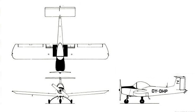
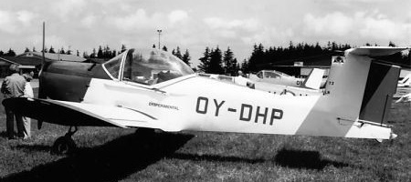
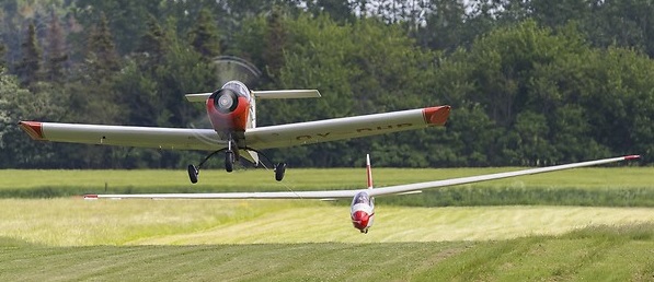
The Polyt V, sometimes written as Polyt 5, was intended from the start as a glider tug. It was designed by six graduates and student members of the Flying Group of the Technical University of Denmark, Copenhagen, (Led by Helge Petersen) a group comprising about 50 students and graduates of that University. As many as 20 other Group members built the aircraft.

It is a low wing, single-seat monoplane with a fixed tricycle undercarriage and a high T-tail, powered by a 200 hp (150 kW) Lycoming IO-360-A2B flat four engine, driving either a Polyteknisk two-blade fixed-pitch wooden propeller or a Hoffmann HO27-HM-205B-105 two-blade propeller.

For cooling the engine during low-speed flight, a 21 in (53 cm) diameter fan with 16 plastic blades is mounted in the circular air intake behind the propeller and is capable of blowing some 3,500 cu.ft (99 cu.m) of air per minute – about four times the normal cooling flow. To prevent excessive cooling the under-nose cooling flap aft of the cowling closes automatically during a dive. Fuel in two aluminum tanks in the wings, total capacity 23.24 gal (88 l). Overwing refueling point in each tank. Oil capacity 1.98 gal (7.5 l).

Its wings are built around a wooden box spar and plywood covered except for fibreglass leading edges. Wing section NACA 63-618 at root, NACA 63-218 at tip. Dihedral 4° from roots. Incidence 2°. No sweepback. They carry wide span ailerons with centrally-located trim tabs; inboard are glider style aluminium spoilers or airbrakes which can be extended to 50° to slow the aircraft after a diving release of the glider. When deployed, the spoiler surfaces extend both below and above the wing, the upper part perforated. These surfaces are carried on a shaft at 80% chord, the portion ahead of this shaft being perforated and the rear portion plain. Of aluminum construction, they have a maximum deflection of 50°; their use has no affect on lift or trim.

The tail surfaces are all wood structurally, with plywood covered fixed surfaces and a fabric covered rudder with a short trim tab. The all moving, fabric covered, constant chord tailplane carries full span anti-tabs. Trim tab in rudder.

The fuselage of the Polyt V is a plywood covered box structure, the pilot sitting over the wing under a single piece, rearward-sliding canopy. An electrically driven winch at the rear retrieves the launch cable, which exits the aircraft at the narrow extreme stern of the fuselage, at a rate of about 1 m/s.

Non-retractable tricycle type landing gear. The main wheels are mounted on a 3 m diameter semi-circular glass fibre gear legs one-third arc of a circle of 6 ft 6.5 in (2.00 m) diameter attached to the fuselage underside Cessna CFP 4097 main wheels. The nose wheel unit (leg, wheel and shock-absorber) is largely that of a Piper Colt, fitted with shimmy damper from a Cessna 172. All tires size 600 x 6, pressure 24 lb/sq.in (1.69 kg/sq.cm).

Accommodation is a single seat for pilot under fully-transparent rearward-sliding canopy. Cockpit heated and ventilated. Electrical system includes AC alternator and 12V battery for engine starting, instruments, lights and towing winch. Vacuum pump for directional gyro. Equipment includes an electrically-operated winch in the rear fuselage, which can reel in over 130 ft (ca. 40 m) of nylon tow line in 40 sec after sailplane is released. Aircraft can make seven or eight launches an hour.

The Polyt V flew for the first time on 12 April 1970, construction having started in 1965. The Polyteknisk Flyvegruppe have used the sole Polyt V to launch their various gliders from 1970 to at least 2006. OY-DHP (c/n 12001) remained on the Danish register in 2010 and was still active as a glider tug. Some modifications have been made: the original Polyteknisk designed propeller, optimised for low speed flight has been replaced by a quieter Hoffmann one and the rudder trim tab has been extended to half rudder height.

Specifications
Engine: 1 × Lycoming IO-360-A2B, 150 kW (200 hp)
Propeller: 2-bladed Polyteknisk designed wooden fixed pitch
Prop diameter: 2.05 m (6 ft 9 in)
Length: 6.20 m (20 ft 4 in)
Wingspan: 9.60 m (31 ft 6 in)
Wing aspect ratio: 6.35
Wing chord, constant: 4 ft 11 in (1.50 m)
Height: 2.60 m (8 ft 6 in)
Wing area: 14.4 m2 (155 sq ft)
Empty weight: 615 kg (1,356 lb)
Max takeoff weight: 760 kg (1,676 lb)
Wing loading: 10.8 lb/sq.ft (52.8 kg/sq.m)
Power loading: 8.38 lb/hp (3.8 kg/hp)
Tailplane span: 9 ft 10 in (3.00 m)
Ailerons area (total) : 17.87 sq.ft (1.66 sq.m)
Air-brakes/flaps area (total): 10.98 sq.ft (1.02 sq.m)
Fin area: 12.92 sq.ft (1.20 sq.m)
Rudder area, incl. tab: 5.06 sq.ft (0.47 sq.m)
Tailplane area, incl. tab: 29.06 sq.ft (2.70 sq.m)
Wheel track: 7 ft 0.5 in (2.15 m)
Wheel base: 4 ft 9 in (1.5 m)
Propeller ground clearance: 6 in (15 m)
Maximum speed: 200 km/h (124 mph; 108 kn) at sea level
Max dive speed: 144 mph (232 kmh)
Cruising speed: 185 km/h (115 mph; 100 kn) maximum at sea level
Econ cruise speed: 103.5 mph (166 kmh) at sea level
Stall speed: 46 mph (74 kmh)
Endurance: about 2 hrs
Service ceiling: 5,500 m (18,045 ft)
Climb, solo: 1,575 ft (480 m)/min
Climb, with single-seat glider: 1,050 ft (320 m)/min
Climb, with two-seat glider: 820 ft (250 m)/min
Takeoff run, solo: 280 ft (85 m)
Takeoff run, with single-seat glider: 510 ft (155 m)
Takeoff to 50 ft (15 m), solo: 460 ft (140 m)
Takeoff to 50 ft (15 m), with single-seat glider: 900 ft (275 m)
Landing run from 50 ft (15 m): 920 ft (280 m)
Landing run: 460 ft (140 m)
Crew: 1

Polson Special

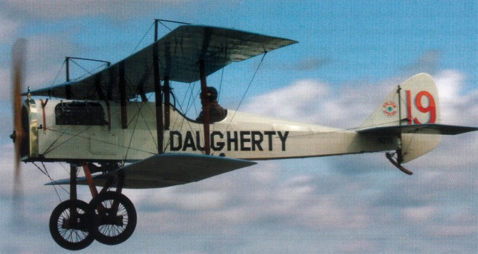
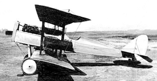
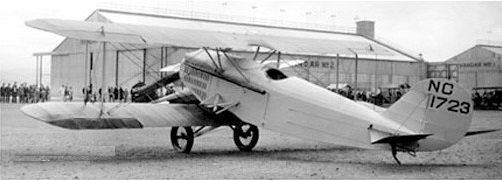
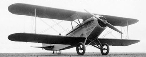
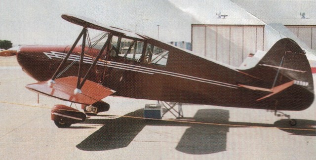
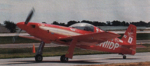
The Polson Special C/NC1723 was built between 1917 and 1925 by Thor Polson of Long Beach, California, for Earl Daugherty who was a regular participant in air shows, stunt displays and air racing post WW 1.

1922

The aircraft was restored by George Jenkins of St. Davids, PA, and flew again from Brodhead, after 83 years.

Engine: OX-5 V-8, 90 hp

1927
1927

Polliwagen Polliwagen

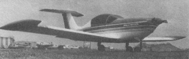
Designed by Argentine-born Joseph Alvarez in 1973, the Polliwagen derives its name from its appearance and its engine type. It is powered by a Revmaster R-2100-D turbocharged Volkswagen conversion. The Revmaster is closely cowled behind a two-position, constant-speed Maloof metal propeller of 59 inches diameter. The Polliwagen’s ex¬ceptionally clean lines give it an excellent speed-to-power ratio as well as fine aerodynamic handling characteristics. The wings are Wort¬mann FX-67-K-1 50 wing section with full-span trailing edge flaps and ailerons. Both the wings and fuselage make use of foam/epoxy com¬posite construction. Prefabricated parts are also offered in the Polliwagen kit including: molded windshield and canopy, landing gear, disc brakes, complete panels, composite structure wingtip fuel tanks, outward-breaking cabin structure, T-tail, etc.
First year built: 1978. Units delivered to June 1981: 300 kits, 65 flying. Price 1982: $5,500 (Excludes engine).

April 1982

Engine 78-hp Revmaster VW
Gross Wt. 1250 lb
Empty Wt. 650 lb
Fuel capacity 25 USG
Wingspan 26 ft
Length 16 ft
Wing area: 90 sq.ft
Top 200+ mph
Cruise 180 mph
Stall 51 mph
Climb rate 925 fpm
Range 1000 fpm
Takeoff run 500 ft
Landing roll 500 ft
Seats: 2

Polikarpov ARK-5

Mikhail Vodopyanov during the salvation of the crew of the steamship Chelyuskin used an R-5 specially prepared for Arctic operations. On these flights Molokov used the containers for people designed by Grojovski, which allowed him to save 39.

In correspondence with the polar exploration plans of the 30s the management of the Glavsievmorputi prepared for 1936 a flight from Moscow to Franz Josef Land. This flight was not intended to break any records, it was only to study the access routes for the conquest of the North Pole, the recognition of flight paths and the conditions of the ice in the Kara and Barents Seas. Pilots were also required to collect information on climate and weather changes.

For this task two examples with closed cabins were modified. The changes in this case were very careful. This modification would be named Polikarpov ARK-5 (Russian: Поликарпов АРК-5) to highlight its Arctic use.

The crew of the ARK-5 was increased to three people. The cabin was modified and equipped with a heating system from hot air from the engine. The overboard containers, previously used on the LP-5s, were enlarged so that spare propellers, skis, tents and an inflatable boat could be stored.

All the equipment was calculated so that in case of a breakdown the crew would be able to return to the mainland by their own means, counting on food reserves for the three crew members for 45 days.

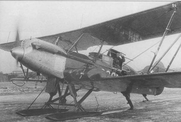
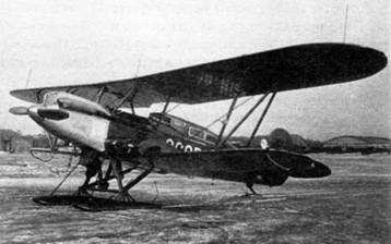
Built at Glavsievmorputi Workshops, both aircraft received registrations of the Glavsievmorputi СССР Н-127 and СССР Н-128 and were painted in intense green and red colors.

March 28, 1936

The main aircraft, with number Н-127 was equipped with radio beacon and radio compass, radio station MRK-0.04 with a rigid antenna on the upper plane. The Н-128 received lighter equipment, being equipped with a shortwave radio station for ground contacts and with the Н-127.

As commander of the expedition was appointed M. V. Vodopyanov. Its crew consisted of mechanic F. I. Bassein and radista S. A. Ivanov. The second aircraft was flown by V. M. Majotkin, with V. L. Ivashin as mechanic and V. I. Akkuratov as radio operator.

ARK-5 of M. V. Vodopyanov at Moscow airfield in March 1936.

The planes took off on March 28, 1936 and in general the route did not present problems, which demonstrated the feasibility of flights at high latitudes. This expedition allowed to gain experiences in the preparation of future expeditions and to develop the idea of landing groups at the North Pole, which would be carried out in 1937.

On May 21, only one plane, the Н-127, arrived in Moscow. The second plane was damaged on the way back, near Tijaya Bay.

At the time of the breakdown the crew was in good physical condition. The plane was abandoned and the crew picked up by an icebreaker.

In 1935, two new ARK-35s were prepared at the Repair Factory No.5 in Smolensk.

These aircraft were characterized by the structure of the cabin deck made of steel. Part of the fuselage structure was replaced by duralumin parts.

In the front cockpit was the pilot and in the rear the mechanic, the radista and two passengers. The side containers were enlarged. On the left a compressor was installed with its engine, which allowed the engine to be started from compressed air even after a long stay on land.

At the front of the containers electric current generators were installed using fans. The one on the left for the radio station and the one on the right for lighting. One of these aircraft received a radio compass.

Polikarpov 2B-R2

In March 1919 Polikarpov was selected as head of the technical department of the former Duks factory, soon to be renamed State Aviation Factory No.1 or GAZ No.1. In 1920, the first Soviet aircraft would be projected and built in GAZ No.1 and just three years later, it would already plan the construction of a multi-engine military aircraft known as 2B-L1 and powered by two 400 hp Liberty engines.

Nikolai Polikarpov’s construction activity was generally linked to fighters, but Polikarpov’s beginnings in aviation were directly linked to the Ilya Múromets bombers designed by Igor Sikorsky.

The development of this bomber began at GAZ No.1 in 1924 and the project was led by engineer L. D. Kolpakov-Miroshnichenko. Polikarpov had no relationship with the development of this project, since with the arrival of D. P. Grigorovich he would be excluded from the factory and transferred to the Glavnoavia aeronautical construction department. However, by the fall of that same year, after Grigorovich’s departure, Polikarpov would return to GAZ No.1 as head of the construction bureau. Once in this position he refused to take part in the construction of the 2B-L1 and acting as a consultant, he basically became a critic of the bomber.

The plane, however, began to be built. The VVS, foreseeing the possibility of practical use of the model, decided to replace the designation 2B-L1 with B-1, but it would soon become clear that the new bomber did not satisfy many of the requirements imposed by the military. This was the main reason why, even without finishing the B-1, it was decided to start working on a new bomber, which was called the B-2.

According to the requirements issued by the VVS management, the new bomber had to incorporate 3 to 4 Liberty engines. The B-2 should lift a weight of 1000 kg with an average speed of 170 km/h and transport it over a distance of 1000 km.

To meet this new requirement, the GAZ No.1 construction bureau developed six possible bomber variants:

  1. 4B-L3 – biplane with 4 Liberty engines and takeoff weight of 9 tons;
  2. 4B-L3 – biplane with 4 Liberty engines and takeoff weight of 10 tons;
  3. 4B-L3 – sesquiplane with 4 Liberty engines and takeoff weight of 11 tons;
  4. 3B-L3 – sesquiplane with 3 Liberty engines and takeoff weight of 9 tons;
  5. 3B-L3 – monoplane with 3 Liberty engines and takeoff weight of 8-9 tons;
  6. 4B-L3 – monoplane with 4 Liberty engines and takeoff weight of 10 tons.

Within this list were included projects by Polikarpov, Kolpakov-Miroshnichenko and Krylov.

Interest in these works remained between July and October 1925, but by this date it had already been decided to abandon the option of the Liberty engine, considering it lacking in perspective and to redesign the bombers with two 600-hp Wright Tornado North American engines.

As a basis for this new design, it was decided to use the French Farman Goliath bomber. Several of these aircraft had been acquired and arrived in Leningrad at the beginning of October.

To evaluate this foreign bomber and become familiar with its assembly, it was decided to send a group of specialists from GAZ No.1 to Leningrad. Polikarpov managed to ensure that neither Kolpakov-Miroshnichenko nor Krylov were included in this group, leaving the competition aside.

Already in the autumn of 1924 Polikarpov, head of the construction bureau and later head of the experimental department, had managed to establish a new, more effective system of work organization. The main objective of this new system was destined to gradually relegate the work of the old engineer-builders, accustomed to developing, approving and building their models based on their customs and points of view. The new structure of the OKB planned to use a system similar to the one adopted by A. N. Tupolev at the TsAGI, where a group of engineers defined the general concepts and then the different departments worked on the development of the components and systems.

The new B-2 bomber with two Wright Tornado engines, in its development stage began to be called GAZ No.1 2B-R2. The project began development in the spring of 1926.

Because the Wright Tornado engine had to be used in other types of devices, the possibility of buying a certain amount and then copying the model was valued, in the same way that this had been achieved with the Liberty.

The 2B-R2 was designed as a twin-engine biplane of mixed construction and was characterized by its bi-derived tail with double horizontal planes. The landing gear was of the conventional and fixed type.

Despite the great projection work carried out and the progress in the work, in April 1926 it was decided to cancel the VVS request for the 2B-R2 bomber. The main reason was the appearance of the all-metal Tupolev ANT-4 bomber, developed at TsAGI at the request of the Ostiexbyuró. The VVS management, pleased with the results of this new model, otherwise quite superior to the 2B-2R, decided to introduce it into service with the designation TB-1.

After a year and the appearance of some problems in the development of the TB-1 due to the lack of practice in the use of metal construction, it was decided to develop an alternative version of mixed construction. This job was assigned to Polikarpov’s collective and would be the basis for the TB-2 bomber.

2B-R2
Engines: Two 600 hp Wright Tornado
Empty weight: 5200 kg
Maximum takeoff weight: 9150 kg
Payload: 3950 kg
Maximum speed: 180 km/h
Practical ceiling: 4000 m
Bombload: 1500 kg
Accommodation: 5