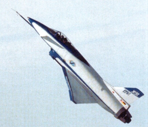
The X 31 began as an Enhanced Fighter Manoeuvrability (EFM) demonstrator at NASA’s Dryden Flight Research Center at Edwards AFB. Designed to break the “stall barrier,” allowing it to flight at angles of attack which would typically cause an aircraft to stall with a complete loss of control, the X-31 employs thrust vectoring paddles that are located in the jet exhaust and small computer-controlled canards to help keep the aircraft stable at high attack angles. It incorporates an unusual delta wing design and three thrust vectoring paddles made of graphite epoxy and located on the aircraft’s aft fuselage. These direct the engine exhaust to provide control in pitch (up and down) and yaw (right and left) thereby increasing the aircraft’s manoeuvrability. In addition, the X 31 is configured with movable forward canards, wing control surfaces and fixed aft strakes. Coupled with advanced flight control systems, the result confers a significant advantage over conventional fighters in a close in combat situation.
The X 31 is the first co operative international X plane. At Dryden, the International Test Organization (ITO) expanded the flight test envelope. The ITO, managed by the Advanced Research Project Agency (ARPA), includes NASA, the US Navy, the US Air Force, Rockwell Aerospace, the Federal Republic of Germany and Deutsche Aerospace, formerly Messerschmitt Bolkow-Blohm.
To reduce costs, several parts of existing aircraft were used in the X 31. Canopy, ejection seat and control stick were taken from an F/A 18 while several parts of the landing gear and rudder are from an F 16. Brakes and wheels were provided by Cessna and are the same as those used on the Cessna Citation. Piloted by Rockwell chief test pilot Ken Dyson, the first aircraft, serial 164584, flew from Air Force Plant 42, Palmdale, Calif, on October 11, 1990. The second aircraft, 164585, made its first flight on January 19, 1991, with Deutsche Aerospace chief test pilot Dietrich Seeck at the controls. Powered by a single General Electric P404 GE 400 turbofan engine, known to be tolerant in disturbed air and capable to produce 16,000 lb of thrust with afterburner, the maximum speed achieved by the X 31 is Mach 1.28. Controlled flight at 70o angle of attack was accomplished at Dryden on November 6, 1992. On April 29, 1993, the X 31 successfully executed a rapid minimum radius, 180o turn using a post stall manoeuvre, flying well beyond the aerodynamic limits of any conventional aircraft. Later that summer, the first simulated dog-fights were performed against a NASA F/A-18 Hornet. This resulted in 63 victories for the X-31.
The first X-31 was lost in an accident on January 19, 1995, on its 292nd flight. Due to miscommunication between pilot and air traffic control and a missing pitot tube heating system the German pilot, Karl Heinz Lang, had to eject from his uncontrollable aircraft at 18,000ft. The aircraft crashed near Edwards AFB.
The second X-31 completed the 580th and last flight of its original research program on 13 May 1995 and was placed in storage.
In February 1998, the participating contractors started VECTOR Risk Reduction and Requirements Definition. The aircraft was shipped to NAS Patuxent River in April 2000, where it was largely rebuilt for the Vector (Vectoring Extremely Short Take-Off and Landing Control Tailless Operation Research) program.
VECTOR stands for Vectoring Extremely Short Take-Off and Landing Control and Tailless Operational Research and is being used to research extremely short take off and landing capabilities and also the aerodynamic characteristics of tailless flight using integrated thrust vector control. Three technology areas are involved: Extremely Short Take Off and Landing (ESTOL) using thrust vectoring control
Flush Air Data System (FADS)
Tailless/reduced vertical tail configurations
This incorporated a new flight control software system was installed together with an auto throttle system, a belly mounted video camera and components of inertial navigation and global positioning systems. The revised aircraft made its first flight for Vector on 24 February 2001. After two months of basic flight testing, the aircraft began a year of upgrading and ground testing to perform ESTOL landings to a “virtual runway” at 5,000 feet. The X-31 took to the air again on 17 May 2002.
In these flights the aircraft flew thrust vectored, high precision ESTOL landings at reduced speeds and at high angles of attack.
To perform the automated approach, the pilot must fly into an invisible engagement box in the sky, then activate the ESTOL mode. Once successfully engaged, the pilot is not in control but is able to override the approach at any point. A video camera under the belly of the aircraft will allow the pilot to view the runway prior to landing because a pilot loses sight at anything above 15 degree angle of attack, so during final approach the aircraft will be controlled by autopilot. Coming in with its nose pointed high above the horizon, the first part of the aircraft to touch the runway would be the engine nozzle and not the landing gear. To prevent such an event, the X 31 performs [an automatic] derotation manoeuvre when the tail is just two feet above the runway, dropping onto its main landing gear. Timing of this manoeuvre is crucial; if the aircraft derotates early and drops too far, the landing gear could fail; if the aircraft derotates too late or too low, the tail could strike the runway. The aircraft is guided during approach by an Integrity Beacon Landing System (IBLS) which uses differential GPS data together with ground-based beacons to determine the aircraft’s position ensuring accurate positioning within two centimetres.
After 51 flights, the X 31 completed its first test phase on March 22, 2003, with two supersonic flights focussing on FADS performance. Pilot Knoptel reached speeds of Mach 1.06 and 1.18, in full afterburner at 39,000ft. While supersonic, he induced combinations of angle of attack and sideslip to tax the FADS. By night, engineers had processed the data and were able to confirm that the FADS was performing as desired throughout the flight regime.
This cleared the way for the final phase of flight tests that began in early April 2003 and ended on April 29 when the last ESTOL landing was performed by Maj Allee following a week of successful testing the world’s first fully automated, thrust vectoring landings. This landing was performed with an angle of attack of 24 o and a speed of 121kt, a reduction of 31% compared with the normal landing speed of 175kt. The X 31 requires a normal runway length of 8,000ft to stop after a conventional landing, but after the final ESTOL landing, the aircraft needed just 1,700ft to slow down enough to turn around on the runway.
Sponsors: DARPA, USN, German MoD Fastest Flight: Mach 1.28 (900 mph) Highest Flight: 40,000 feet (approx)
X 31 Powerplant: One General Electric P404¬GE 400 turbofan, 16,0001b thrust with afterburner Span; 23,83ft (7.3m) Length, 43.33ft (12.8m) Take off weight, 16,1001b (7,303kg) Max achieved speed, Mach 1,28 at 35,000ft Max achieved altitude, 40,000ft (12,200m)
X-31A Powerplant: one 10,600-lb (4808-kg) thrust General Electric F404-GE-400 non-afterburning turbofan Wingspan 23 ft 10 in (7.26 m) Length 43 ft 4 in (13.21 m) excluding probe Height 14 ft 7 in (4.44 m) Wing area 226.3 sq ft (21.02 sq.m) Canard foreplane area 23.6 sq ft (2.19 sq.m) Maximum speed 597 mph (961 km/h) or Mach 0.9 at 35,000 ft (10,670 m) Empty weight 10,212 lb (4632 kg) Maximum take-off 13,968 lb (6335 kg) Crew: 1
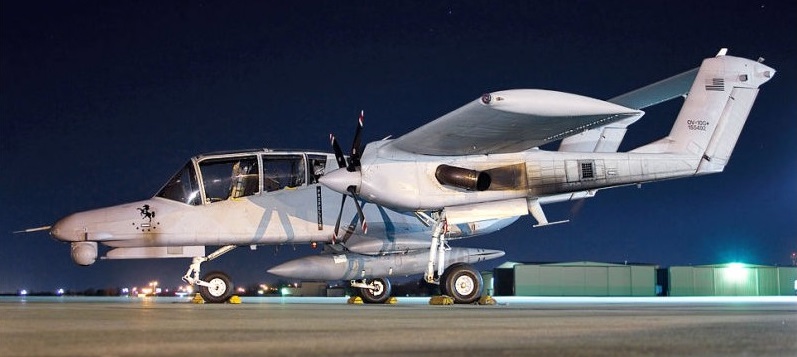
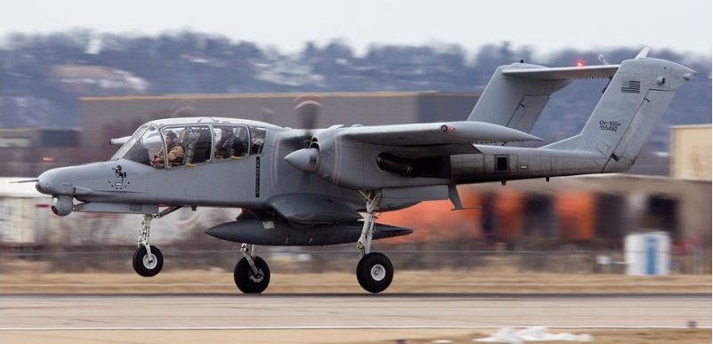
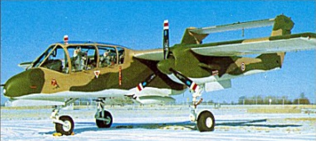
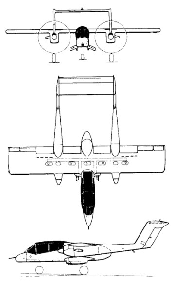
To meet a US Navy requirement for a light armed recon¬naissance aircraft, North American Rockwell produced their NA-300 design submission for the OV 10A Bronco. A contract for seven YOV-10A prototypes was placed in 1964, the first of them flying on 16 July 1965.
With a two-seat fuselage nacelle mounting a high-set monoplane wing, the aircraft had twin tailbooms extending aft from the nacelles of the two turboprop engines, each with a fin and rudder, and interconnected by a tailplane/elevator assembly. The main units of the tricycle landing gear retracted into the engine nacelles.
Six of the prototypes were powered by 447kW Garrett T76-G-6/8 engines, but had one Pratt & Whitney YT74-CP-8/10 turboprops for comparative evaluation.
The OV-10A Bronco production version had a 3.05m increase in wing span and more powerful T76-G-10/12 engines, the first flown on 6 August 1967, and 114 were built for the US Marine Corps.
These were followed by 157 similar OV-10As for the US Air Force, these entering operational service in Vietnam in 1968. Under the US ‘Pave Nail’ programme, 15 were provided with special equipment for the location and illumination of targets by night. Other versions have included six OV-10B aircraft supplied to Germany as target tugs, followed by 18 turbojet-boosted OV-10B(Z) aircraft for the same role. Versions similar to the OV-10A have been supplied to Indonesia (16), Thailand (40) and Venezuela (16), under the respective designations OV-10F, OV-10C and OV-10E, and six US OV-10As have been transferred to the Royal Moroccan air force.
Two OV-10As were modified under a US Navy contract of 1970 to YOV-10D NOGS (Night Observation/Gunship System) aircraft to provide the US Marines with advanced night operational capability. Since evaluation of these aircraft, 17 US Marine Corps OV-10As have been converted to OV-10D NOS (Night Observation Surveillance) configuration, now equipped with a FLIR (forward-looking infra-red) turret in the nose linked to an underfuselage 20mm cannon turret, and a laser target illuminator.
Production of the Bronco for the USMC, USAF, and four export customers was completed in 1980.
Able to carry a maximum weapon load of 3,600 lb (1,633 kg), the Bronco has proved valuable for Forward Air Control (FAC) operations in South East Asia.
Of the seven prototype North American Rockwell OV 10 Broncos built, No.3 on the line was heavily modified and was the only short-wing example of the aircraft ever built. YOV 10A 152881 (N718NA) has a wingspan of only 32ft (9.75m), whereas standard production aircraft had 40ft (12m) of wing. From 1966 to 1972 the aircraft was used as a demonstration airframe and was used to take Admirals, Generals and Congressmen for flights to extol the virtues of the twin engined observation and forward air controller design. The Bronco was also assigned to train new pilots on the gunnery ranges, using its machine guns and rockets. During the spring of 1972 it was assigned to NASA under the Department of the Army, for STOL flight testing. This was carried out at the Ames Flight Test Center in California, with the aircraft being allocated a civilian registration.
During its time at Ames, the Bronco was heavily modified, the aircraft’s Garrett T 76 turboprops were removed and replaced by Lycoming T 54s. Three blade 7ft (2.1m) Hamilton Standard propellers were replaced with 10ft (3m) four bladed Curtiss Electric composite propellers, and the engines were interconnected by a single solid shaft in the leading edge of the wing. With this system in operation, the aircraft flew at 47 knots and NASA was working toward getting the minimum speed down to 30 knots. The Bronco became unstable, and the programme was stopped. The aircraft was with NASA until it was sold to the Detroit Institute of Aeronautics in 1979.
OV-10A Engines: 2 x Garrett AiResearch T76-G-416/417, 715 shp Wing span: 40 ft 0 in (12.19 m) Wing area: 290.951 sqft / 27.03 sq.m Length: 41 ft 7 in (12.67 m) Height: 15 ft 2 in (4.62 m) Max TO wt: 14,446 lb (6563 kg) Weight empty: 6892.8 lb / 3126.0 kg Max level speed: 281 mph (452 kph) Cruising speed: 168 kts / 312 km/h Service ceiling : 27001 ft / 8230 m Maximum range: 1199 nm / 2220 km Range (max. weight): 410 nm / 760 km Crew: 2 Armament: 4x MG 7,62mm M60C/500rds., 1633kg ext. 5pts.
OV-10B Engines: 2 x Garrett T76-G-418
OV-10D Engines: 2 x Garrett T76-G-420/421 turbo-prop, 776kW / 1040 shp Max take-off weight: 6552 kg / 14445 lb Empty weight: 3127 kg / 6894 lb Wingspan: 12.19 m / 39 ft 12 in Length: 13.41 m / 43 ft 12 in Height: 4.62 m / 15 ft 2 in Wing area: 27.03 sq.m / 290.95 sq ft Ceiling: 9145 m / 30000 ft Range w/max.payload: 740 km / 460 miles Bombload: 2000kg Crew: 2
The Rockwell B-1 resulted from a November 1969 requirement for a medium-altitude with dash capability of Mach 2.2+ for the high-speed delivery of free-fall and stand-off nuclear weapons. Submissions were received from several companies, Rockwell’s design being selected in 1970 as the B-1A. The full-scale design and development programme for the initial production version was soon under way. The initial model was a complex and highly advanced variable-geometry type with General Electric F101 turbofans and fully variable inlets for maximum capability in all elements of the flight envelope.
The first of four prototypes (71-40158) of the Rockwell International B-1 four-turbofan strategic heavy bomber made its maiden flight on 23 December 1974; designed to meet USAF Strategic Air Command’s Advanced Manned Strategic Aircraft (AMSA) requirement, it incorporated variable geometry wings (maximum sweep of 67 degrees), accommodated a four-man crew and had an estimated maximum speed of Mach 2 at altitude.
In June 1977 President Carter decided to scrap the programme in favour of cruise missile development although flight trials with the B-1A aircraft were to be continued for research purposes, the flight testing continued through 1981 with the four prototypes.
Then with the inauguration of President Reagan matters began to look up again, the new administration deciding during October 1981 to procure 100 examples of a much revised B-1B version in the low-level penetration role for high-subsonic delivery of free-fall and stand-off weapons. The B-lB was.therefore a straightforward but nonetheless major adaptation of the B-1A optimized for the low-level transonic role with fixed inlets and revised nacelles (reducing maximum speed to Mach 1.25). But it did have a strengthened airframe and landing gear for operation at higher weights with nuclear and conventional weapons over very long ranges. Other changes were concerned with reduction of the type’s already low radar signature, S-shaped ducts with streamwise baffles being adopted to shield the face of the engine compressors and radar absorbent materials being installed in sensitive areas to reduce electromagnetic reflectivity. The second and fourth B-lAs were used from March 1983 to flight-test features of the B-1B, which first flew in September 1984 with the advanced offensive and defensive electronic systems.
In conjunction with the USAF, Edwards AFB, ASA Dryden Flight Research Center carried out two six-hour flights of the B-1, with the first taking place on 25 March 1981. B-1 number 3, part of the USAF/Rockwell joint test force Bomber Penetration Evaluation was utilised for the two flights. The two supersonic flights evaluated the Structural Mode Control System.
The first production B-1B flew on October 18, 1984, some five months ahead of schedule. Two B-1A development aircraft had previously been converted to B-1B standard, the first flying in B-1B form in March 1983. Production deliveries began in July 1985, to replace B-52Hs in the penetration role, and will continue until 1988.
The ninth B-1B was the first to be fitted with a moveable bulkhead in the forward weapons bay, enabling it to carry eight AGM-86 air-launched cruise missiles (ALCM), short-range attack missiles (Sram), and extra fuel tanks internally. Maximum ALCM loading is eight missiles internally and 14 externally on eight underfuselage hardpoints.
Initial Operational Capability was first achieved on 1 October 1986.
In January 1987 a B-1B successfully launched a short-range-attack missile for the first time, while in April an aircraft from the 96th Bomb Wing at Dyess AFB, Texas, completed a 2l hr 40min mission including five in-flight refuellings (to maintain a high aircraft weight), covering a distance of 15,145km (8,175 nm).
The final B-1B was delivered 2 May 1988.
In 1989, when Neil Armstrong became chairman of AIL Systems Inc., he was invited to fly the B-1 bomber. He later flew the B-1 again for the first flights television series.
The B-1B Lancer were modified and aircrews were trained for the use of conventional weapons, including stand-off and laser guided weapons, and did flew combat missions during Operation Desert Fox.
Also in 1999 the B-1s flew bombing missions using conventional weapons against Yugoslavia as part of Operation Allied Force.
Rockwell became responsible in 1972 for development of the US Navy’s XFV-12A V/STOL Fighter/Attack Technology Prototype programme.
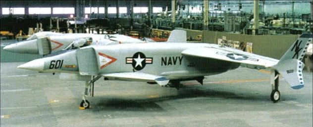
Basically a single-seat all-weather V/STOL fighter/ attack aircraft, the XFV-12A made use of an augmentor wing concept in which the efflux of its single Pratt & Whitney F401-PW-400 afterburning turbofan engine could be diverted to nozzles in the wings and foreplanes for V/STOL operations.
An ejector-flap system was incorporated in the design of each wing and foreplane, in which ambient air was mixed with turbine efflux in a ratio of 7:1 to provide the essential jet-lift for vertical operations and, when the flaps are raised or lowered progressively, for transition from vertical to horizontal flight and vice versa.
The main landing gear, canopy and other cockpit parts came from an A-4 Skyhawk. The main wing box and parts of the inlets were from an F-4 Phantom.
The XFV-12 did get off the ground – and was tested in a tethered mode, but the programme proved a disappointment and failed to provide an alternative to the Harrier.
Engine: 1 x 133.4kN Pratt & Whitney F401-PW-400 turbofan Max take-off weight: 11000 kg / 24251 lb Wingspan: 8.69 m / 29 ft 6 in Length: 13.35 m / 44 ft 10 in Height: 3.15 m / 10 ft 4 in
Rockwell-Standard Corp North American Rockwell Corp Rockwell International Corp
In 1919, Colonel W.R. Rockwell reorganised a bankrupt axle company in Oshkosh, Wisconsin. Following the Colonel’s development of the first double reduction axles for heavy-duty vehicles, Timken-Detroit Axle company acquired his axle company in 1928.
In 1953, Timken-Detroit merged with Standard Steel Spring Company to form Rockwell Spring and Axle Company. In 1958, the name of the company was changed to Rockwell-Standard Corporation. Rockwell-Standard embarked on a plan of diversification in the late 1950s and 60s and by 1967, it was a major independent producer of a wide-range of automotive components.
In 1965 Rockwell-Standard acquired Snow Aeronautical, continuing to produce agricultural aircraft at Olney as Snow Commanders (as division of Aero Commander), and acquired Intermountain Manufacturing Company (IMCO) 1966. Single-engined Model 112 delivered to customers from 1972. Low-wing twin-engined Rockwell Commander 700 produced jointly with Fuji in Japan. Thrush Commander was very notable specially-designed agricultural aircraft. The entire Thrush Commander range sold to Ayres Corp and then became known by the Ayres name. Shrike Commander 500S terminated 1980 but Commander Jetprops continued by Gulfstream American Corporation.
In 1967, Rockwell-Standard Corporation and North American Aviation merged to create the North American Rockwell Corporation.
Following company reorganization, the former Aero Commander division of Rockwell became part of NAR, and its Shrike, Commander 685 and Turbo Hawk Commander twin-engined business aircraft were marketed under the new company name, together with Quail, Sparrow, Snipe and Thrush Commander agricultural aircraft, and the Darter and Lark Commander single-engined lightplanes.
The Model 112 Commander lightplane and B-1 swing-wing supersonic bomber projects were started before the company name was changed to Rockwell International in 1973.
In 1973 North American Rockwell and Rockwell Manufacturing Company merged to become Rockwell International Corporation. Aircraft production after the 1967 merger included the Aero Commander line of single and twin-engine aircraft, the turboprop OV-10 Bronco armed reconnaissance aircraft, T-2 Buckeye jet trainer, B-1B Lancer supersonic swing-wing bomber, and the Sabreliner executive and light jet transport. Company’s aerospace and defence units purchased by the Boeing Company on December 6,1996, becoming Boeing North American. Similarly, Rockwell Australia became Boeing Australia Ltd.
In 1977 Rockwell International sold its agricultural airplane operation to the Ayres Corporation of Albany, Georgia. The new owners will continue to manufacture the Models 600 and 800 Thrush Commanders. Fred Ayres, who developed the Turbo Thrush PT6 retrofit, plans to begin producing that airplane at his new plant.
1984: Sabreliner Corporation, a new company formed to acquire the former Sabreliner Division of Rockwell International.
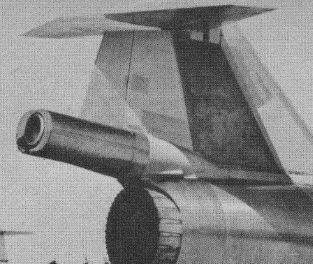
The Rocketdyne AR-2 is fitted above and aft of the J79 engine in the Lockheed NF-104A. To attain a 25 mile altitude the 6000 lb thrust engine burns a mixture of JP-4 jet fuel and hydrogen peroxide.
The AR-2 is throttleable from 50 to 100% power. The NF-104A provides spaceflight experience at a fraction of X-15 operating costs.
The RS-25, otherwise known as the Space Shuttle Main Engine (SSME), is a liquid-fuel cryogenic rocket engine that was used on NASA’s Space Shuttle. Built in the United States by Rocketdyne, the RS-25 burns cryogenic liquid hydrogen & liquid oxygen propellants, with each engine producing 1,859 kN (418,000 lbf) of thrust at liftoff. Although the RS-25 can trace its heritage back to the 1960s, concerted development of the engine began in the 1970s, with the first flight, STS-1, occurring on April 12, 1981. The RS-25 has undergone several upgrades over its operational history to improve the engine’s reliability, safety and maintenance load.
The engine produces a specific impulse (Isp) of 453 seconds (4.44 km/s) in a vacuum, or 363 seconds (3.56 km/s) at sea level, consumes 1,340 L (350 US gal) of propellant per second, has a mass of approximately 3.5 tonnes (7,700 pounds) and is capable of throttling between 67% and 111% of its rated power level in one-percent increments. The RS-25 operates at extreme temperatures, with the liquid hydrogen fuel being stored at −250 °C (−418 °F) while the temperature in the combustion chamber reaches 3,315 °C (6,000 °F), higher than the boiling point of iron.
On the Space Shuttle, the RS-25 was used in clusters of three engines mounted in the aft structure of the Orbiter, with fuel being drawn from the external tank. The engines were used for propulsion during the entirety of the spacecraft’s ascent, with additional thrust being provided by two solid rocket boosters and the orbiter’s two AJ-10-190 Orbital Maneuvering System engines. Following each flight, the engines were removed from the orbiter, inspected and refurbished before being reused on another mission.
The RS-25 engine consists of various pumps, valves and other components which work in concert to produce thrust. Fuel (liquid hydrogen) and oxidizer (liquid oxygen) from the Space Shuttle external tank entered the orbiter at the umbilical disconnect valves, and from there flowed through the orbiter’s main propulsion system (MPS) feed lines; whereas in the Space Launch System (SLS), fuel and oxidizer from the rocket’s core stage will flow directly into the MPS lines. Once in the MPS lines, the fuel and oxidizer each branch out into separate paths to each engine (three on the Space Shuttle, up to five on the SLS). In each branch, prevalves then allow the propellants to enter the engine.
Once in the engine, the propellants flow through low-pressure fuel and oxidizer turbopumps (LPFTP and LPOTP), and from there into high-pressure turbopumps (HPFTP and HPOTP). From these HPTPs the propellants take different routes through the engine. The oxidizer is split into four separate paths: to the oxidizer heat exchanger, which then splits into the oxidizer tank pressurization and pogo suppression systems; to the low pressure oxidiser turbopump (LPOTP); to the high pressure oxidizer preburner, from which it is split into the HPFTP turbine and HPOTP before being reunited in the hot gas manifold and sent on to the main combustion chamber (MCC); or directly into the main combustion chamber (MCC) injectors.
Meanwhile, fuel flows through the main fuel valve into regenerative cooling systems for the nozzle and MCC, or through the chamber coolant valve. Fuel passing through the MCC cooling system then passes back through the LPFTP turbine before being routed either to the fuel tank pressurization system or to the hot gas manifold cooling system (from where it passes into the MCC). Fuel in the nozzle cooling and chamber coolant valve systems is then sent via preburners into the HPFTP turbine and HPOTP before being reunited again in the hot gas manifold, from where it passes into the MCC injectors. Once in the injectors, the propellants are mixed and injected into the main combustion chamber where they are ignited. The burning propellant mixture is then ejected through the throat and bell of the engine’s nozzle, the pressure of which creates the thrust.
The Low Pressure Oxidizer Turbopump (LPOTP) is an axial-flow pump driven by a six-stage turbine powered by liquid oxygen which operates at approximately 5,150 rpm. It boosts the liquid oxygen’s pressure from 0.7 to 2.9 MPa (100 to 420 psi), with the flow from the LPOTP then being supplied to the high-pressure oxidizer turbopump (HPOTP). During engine operation, the pressure boost permits the high-pressure oxidizer turbine to operate at high speeds without cavitating. The LPOTP, which measures approximately 450 by 450 mm (18 by 18 in), is connected to the vehicle propellant ducting and supported in a fixed position by being mounted on the launch vehicle’s structure.
The HPOTP consists of two single-stage centrifugal pumps (a main pump and a preburner pump) mounted on a common shaft and driven by a two-stage, hot-gas turbine. The main pump boosts the liquid oxygen’s pressure from 2.9 to 30 MPa (420 to 4,400 psi) while operating at approximately 28,120 rpm, giving a power output of 23,260 hp. The HPOTP discharge flow splits into several paths, one of which drives the LPOTP turbine. Another path is to, and through, the main oxidizer valve and enters the main combustion chamber. Another small flow path is tapped off and sent to the oxidizer heat exchanger. The liquid oxygen flows through an anti-flood valve that prevents it from entering the heat exchanger until sufficient heat is present for the heat exchanger to utilize the heat contained in the gases discharged from the HPOTP turbine, converting the liquid oxygen to gas. The gas is sent to a manifold and then routed to pressurize the liquid oxygen tank. Another path enters the HPOTP second-stage preburner pump to boost the liquid oxygen’s pressure from 30 to 51 MPa (4,300 psia to 7,400 psia). It passes through the oxidizer preburner oxidizer valve into the oxidizer preburner, and through the fuel preburner oxidizer valve into the fuel preburner. The HPOTP measures approximately 600 by 900 mm (24 by 35 in). It is attached by flanges to the hot-gas manifold.
The HPOTP turbine and HPOTP pumps are mounted on a common shaft. Mixing of the fuel-rich hot gases in the turbine section and the liquid oxygen in the main pump can create a hazard and, to prevent this, the two sections are separated by a cavity that is continuously purged by the engine’s helium supply during engine operation. Two seals minimize leakage into the cavity; one seal is located between the turbine section and the cavity, while the other is between the pump section and cavity. Loss of helium pressure in this cavity results in automatic engine shutdown.
The low-pressure fuel turbopump (LPFTP) is an axial-flow pump driven by a two-stage turbine powered by gaseous hydrogen. It boosts the pressure of the liquid hydrogen from 30 to 276 psia (0.2 to 1.9 MPa) and supplies it to the high-pressure fuel turbopump (HPFTP). During engine operation, the pressure boost provided by the LPFTP permits the HPFTP to operate at high speeds without cavitating. The LPFTP operates at around 16,185 rpm, and is approximately 450 by 600 mm (18 by 24 in) in size. It is connected to the vehicle propellant ducting and is supported in a fixed position by being mounted to the launch vehicle’s structure.
The HPFTP is a three-stage centrifugal pump driven by a two-stage hot-gas turbine. It boosts the pressure of the liquid hydrogen from 1.9 to 45 MPa (276 to 6,515 psia), and operates at approximately 35,360 rpm with a power of 71,140 hp. The discharge flow from the turbopump is routed to, and through, the main valve and is then split into three flow paths. One path is through the jacket of the main combustion chamber, where the hydrogen is used to cool the chamber walls. It is then routed from the main combustion chamber to the LPFTP, where it is used to drive the LPFTP turbine. A small portion of the flow from the LPFTP is then directed to a common manifold from all three engines to form a single path to the liquid hydrogen tank to maintain pressurization. The remaining hydrogen passes between the inner and outer walls of the hot-gas manifold to cool it and is then discharged into the main combustion chamber. A second hydrogen flow path from the main fuel valve is through the engine nozzle (to cool the nozzle). It then joins the third flow path from the chamber coolant valve. This combined flow is then directed to the fuel and oxidizer preburners. The HPFTP is approximately 550 by 1,100 mm (22 by 43 in) in size and is attached to the hot-gas manifold by flanges.
The oxidizer and fuel preburners are welded to the hot-gas manifold. The fuel and oxidizer enter the preburners and are mixed so that efficient combustion can occur. The augmented spark igniter is a small combination chamber located in the center of the injector of each preburner. The two dual-redundant spark igniters, which are activated by the engine controller, are used during the engine start sequence to initiate combustion in each preburner. They are turned off after approximately three seconds because the combustion process is then self-sustaining. The preburners produce the fuel-rich hot gases that pass through the turbines to generate the power needed to operate the high-pressure turbopumps. The oxidizer preburner’s outflow drives a turbine that is connected to the HPOTP and to the oxidizer preburner pump. The fuel preburner’s outflow drives a turbine that is connected to the HPFTP.
The speed of the HPOTP and HPFTP turbines depends on the position of the corresponding oxidizer and fuel preburner oxidizer valves. These valves are positioned by the engine controller, which uses them to throttle the flow of liquid oxygen to the preburners and, thus, control engine thrust. The oxidizer and fuel preburner oxidizer valves increase or decrease the liquid oxygen flow, thus increasing or decreasing preburner chamber pressure, HPOTP and HPFTP turbine speed, and liquid oxygen and gaseous hydrogen flow into the main combustion chamber, which increases or decreases engine thrust. The oxidizer and fuel preburner valves operate together to throttle the engine and maintain a constant 6.03:1 propellant mixture ratio.
The main oxidizer and main fuel valves control the flow of liquid oxygen and liquid hydrogen into the engine and are controlled by each engine controller. When an engine is operating, the main valves are fully open.
Each engine main combustion chamber (MCC) receives fuel-rich hot gas from a hot-gas manifold cooling circuit. The gaseous hydrogen and liquid oxygen enter the chamber at the injector, which mixes the propellants. A small augmented-spark igniter-chamber is located in the center of the injector, and this dual-redundant igniter is used during the engine start sequence to initiate combustion. The igniters are turned off after approximately three seconds because the combustion process is self-sustaining. The main injector and dome assembly is welded to the hot-gas manifold, and the MCC is also bolted to the hot-gas manifold. The MCC comprises a structural shell made of Inconel 718 which is lined with a copper-silver-zirconium alloy called NARloy-Z, developed specifically for the RS-25 in the 1970s. Around 390 channels are machined into the liner wall to carry liquid hydrogen through the liner to provide MCC cooling, as the temperature in the combustion chamber reaches 3,315 °C (5,999 °F) during flight – higher than the boiling point of iron.
The engine’s nozzle is 121 in (3.1 m) long with a diameter of 10.3 in (0.26 m) at its throat and 90.7 in (2.30 m) at its exit. The nozzle is a bell-shaped extension bolted to the main combustion chamber, referred to as a de Laval nozzle. The RS-25 nozzle has an unusually large expansion ratio (about 77.5:1) for the chamber pressure. A nozzle of this ratio would normally undergo flow separation of the jet from the nozzle, which would cause control difficulties and could even mechanically damage the vehicle. To aid the engine’s operation at sea level, however, Rocketdyne engineers varied the angle of the nozzle walls, reducing it near the exit. This raises the pressure just around the rim to between 4.6 and 5.7 psi (32 and 39 kPa), and prevents flow separation. The inner part of the flow is at much lower pressure, around 2 psi (14 kPa) or less. The inner surface of each nozzle is cooled by liquid hydrogen flowing through brazed stainless steel tube wall coolant passages. On the Space Shuttle, a support ring welded to the forward end of the nozzle was the engine attach point to the orbiter-supplied heat shield. Thermal protection was necessary because of the exposure portions of the nozzles experience during the launch, ascent, on-orbit and entry phases of a mission. The insulation consisted of four layers of metallic batting covered with a metallic foil and screening.
Each engine is equipped with a Main Engine Controller (MEC), an integrated computer which controls all of the engine’s functions (through the use of valves) and monitors its performance. Built by Honeywell Aerospace, each MEC originally comprised two redundant Honeywell HDC-601 computers, later upgraded to a system composed of two doubly redundant Motorola 68000 (M68000) processors (for a total of 4 M68000s per controller). Having the controller installed on the engine itself greatly simplifies the wiring between the engine and the launch vehicle, because all the sensors and actuators are connected directly to only the controller, each MEC then being connected to the orbiter’s General Purpose Computers (GPCs) or the SLS’s avionics suite via its own Engine Interface Unit (EIU). Using a dedicated system also simplifies the software and thus improves its reliability.
Two independent dual-CPU computers, A and B, form the controller; giving redundancy to the system. The failure of controller system A automatically leads to a switch-over to controller system B without impeding operational capabilities; the subsequent failure of controller system B would provide a graceful shutdown of the engine. Within each system (A and B), the two M68000s operate in “lock-step”, thereby enabling each system to detect failures by comparing the signal levels on the buses of the two M68000 processors within that system. If differences are encountered between the two buses, then an interrupt is generated and control turned over to the other system. Because of subtle differences between M68000s from Motorola and the second source manufacturer TRW, each system uses M68000s from the same manufacturer (for instance system A would have two Motorola CPUs while system B would have two CPUs manufactured by TRW). Memory for Block I controllers were of the plated-wire type, which functions in a manner similar to magnetic core memory and retains data even after power is turned off. Block II controllers used conventional CMOS static RAM.
The controllers were designed to be tough enough to survive the forces of launch, and proved to be extremely resilient to damage. During the investigation of the Challenger accident the two MECs (from engines 2020 and 2021), recovered from the seafloor, were delivered to Honeywell Aerospace for examination and analysis. One controller was broken open on one side, and both were severely corroded and damaged by marine life. Both units were disassembled and the memory units flushed with deionized water. After they were dried and vacuum baked, data from these units was retrieved for forensic examination.
To control the engine’s output, the MEC operates five hydraulically actuated propellant valves on each engine; the oxidizer preburner oxidizer, fuel preburner oxidizer, main oxidizer, main fuel, and chamber coolant valves. In an emergency, the valves can be fully closed by using the engine’s helium supply system as a backup actuation system.
In the Space Shuttle the main oxidizer and fuel bleed valves were used after shutdown to dump any residual propellant, with residual liquid oxygen venting through the engine and residual liquid hydrogen venting through the liquid hydrogen fill and drain valves. After the dump was completed, the valves closed and remain closed for the remainder of the mission.
A coolant control valve is mounted on the combustion chamber coolant bypass duct of each engine. The engine controller regulates the amount of gaseous hydrogen allowed to bypass the nozzle coolant loop, thus controlling its temperature. The chamber coolant valve is 100% open before engine start. During engine operation, it is 100% open for throttle settings of 100 to 109% for maximum cooling. For throttle settings between 65 to 100%, its position ranged from 66.4 to 100% open for reduced cooling.
Each engine is installed with a gimbal bearing, a universal ball and socket joint which is bolted to the launch vehicle by its upper flange and to the engine by its lower flange. It represents the thrust interface between the engine and the launch vehicle, supporting 7,480 lb (3,390 kg) of engine weight and withstanding over 500,000 lb (230,000 kg) of thrust. As well as providing a means to attach the engine to the launch vehicle, the gimbal bearing allows the engine to be pivoted (or ‘gimballed’) around two axes of freedom with a range of ±10.5°. This motion allows the engine’s thrust vector to be altered, thus steering the vehicle into the correct orientation. The bearing assembly is approximately 290 by 360 mm (11 by 14 in), has a mass of 105 lb (48 kg), and is made of titanium alloy.
The low-pressure oxygen and low-pressure fuel turbopumps were mounted 180 degrees apart on the orbiter’s aft fuselage thrust structure. The lines from the low-pressure turbopumps to the high-pressure turbopumps contain flexible bellows that enable the low-pressure turbopumps to remain stationary while the rest of the engine is gimbaled for thrust vector control, and also to prevent damage to the pumps when loads were applied to them. The liquid hydrogen line from the LPFTP to the HPFTP is insulated to prevent the formation of liquid air.
In addition to fuel and oxidizer systems, the launch vehicle’s Main Propulsion System is also equipped with a helium system consisting of ten storage tanks in addition to various regulators, check valves, distribution lines, and control valves. The system is used in-flight to purge the engine, and it provides pressure for actuating engine valves within the propellant management system and during emergency shutdowns. During entry, on the Space Shuttle, any remaining helium was used to purge the engines during reentry and for repressurization.
The history of the RS-25 traces back to the 1960s when NASA’s Marshall Space Flight Center and Rocketdyne were conducting a series of studies on high-pressure engines, developed from the successful J-2 engine used on the S-II and S-IVB upper stages of the Saturn V rocket during the Apollo program. The studies were conducted under a program to upgrade the Saturn V engines, which produced a design for a 350,000 lbf upper-stage engine known as the HG-3. As funding levels for Apollo wound down the HG-3 was cancelled as well as the replacement for the F-1 engine, the M-1 (the development for which ended in 1968). It was the design for the HG-3 that would form the basis for the RS-25. Meanwhile, in 1967, the US Air Force funded a study into advanced rocket propulsion systems for use during Project Isinglass, with Rocketdyne asked to investigate aerospike engines and Pratt & Whitney (P&W) to research more efficient conventional de Laval nozzle-type engines. At the conclusion of the study, P&W put forward a proposal for a 250,000 lbf engine called the XLR-129. In January 1969 NASA awarded contracts to General Dynamics, Lockheed, McDonnell Douglas and North American Rockwell to initiate early development of the Space Shuttle. As part of these ‘Phase A’ studies, the involved companies selected an upgraded version of the XLR-129, developing 415,000 lbf, as the baseline engine for their designs.
Development of the RS-25 itself began in 1970, when NASA released a request for proposal for ‘Phase B’ main engine concept studies, requiring development of a throttleable, staged combustion, de Laval-type engine, with a high chamber pressure (of around 3000 psi) to “force an advancement of rocket engine technology”. Rocketdyne, P&W and Aerojet General were selected to receive funding although, given P&W’s already-advanced development (demonstrating a working 350,000 lbf concept engine during the year) and Aerojet General’s prior experience in developing the 1,500,000 lbf M-1 engine, Rocketdyne was forced to put a large amount of private money into the design process to allow the company to catch up to its competitors. The request was based on the then-current design of the Space Shuttle which featured two reusable stages, the orbiter and a manned fly-back booster, and required one engine which would be able to power both vehicles via two different nozzles (12 booster engines with 550,000 lbf sea level thrust each and 3 orbiter engines with 632,000 lbf vacuum thrust each). By the time the contract was awarded, budgetary pressures meant that the shuttle’s design had changed to its final orbiter, external tank and two boosters configuration, and so the engine was only required to power the orbiter during ascent. During the year-long ‘Phase B’ study period, Rocketdyne were able to make use of their experience developing the HG-3 engine to design their SSME proposal, producing a prototype by January 1971. The engine made use of a new Rocketdyne-developed copper-zirconium alloy (called NARloy-Z), and was tested on February 12, 1971, producing a chamber pressure of 3172 psi. The three participating companies submitted their engine development bids in April 1971, with Rocketdyne being awarded the contract on July 13, 1971—although work did not begin on engine development until March 31, 1972, due to a legal challenge from P&W.
Following the awarding of the contract, a Preliminary Design Review was carried out in September 1972, followed by a Critical Design Review in September 1976 after which the engine’s design was set and construction of the first set of flight-capable engines began. Final review of all the Space Shuttle’s components, including the engines, was conducted in 1979. The design reviews operated in parallel with several test milestones, initial tests consisting of individual engine components which identified shortcomings with various areas of the design, including the HPFTP, HPOTP, valves, nozzle and fuel preburners. The individual engine component tests were followed by the first test of a complete engine (0002) on March 16, 1977. NASA specified that, prior to the Shuttle’s first flight, the engines must have undergone at least 65,000 seconds of testing, a milestone that was reached on March 23, 1980, with the engine having undergone 110,253 seconds of testing by the time of STS-1 both on test stands at Stennis Space Center and installed on the Main Propulsion Test Article (MPTA). The first set of engines (2005, 2006 and 2007) were delivered to Kennedy Space Center in 1979 and installed on Columbia, before being removed in 1980 for further testing and reinstalled on the orbiter. The engines, which were of the First Manned Orbital Flight (FMOF) configuration and certified for operation at 100% Rated Power Level (RPL), were operated in a twenty-second Flight Readiness Firing on February 20, 1981, and, after inspection, declared ready for flight.
Each Space Shuttle had three RS-25 engines, installed in the aft structure of the Space Shuttle orbiter in the Orbiter Processing Facility prior to the orbiter being transferred to the Vehicle Assembly Building. If necessary the engines could be changed on the pad. The engines, drawing propellant from the Space Shuttle external tank (ET) via the orbiter’s Main Propulsion System (MPS), were ignited at T-6.6 seconds prior to liftoff (with each ignition staggered by 120 ms), which allowed their performance to be checked prior to ignition of the Space Shuttle Solid Rocket Boosters (SRBs), which committed the shuttle to the launch. At launch, the engines would be operating at 100% RPL, throttling up to 104.5% immediately following liftoff. The engines would maintain this power level until around T+40 seconds, where they would be throttled back to around 70% to reduce the loads on the shuttle stack as it passed through the sound barrier (and in the case of the shuttle the point of maximum dynamic pressure, or Max-Q). The engines would then be throttled back up until around T+8 minutes, at which point they would be gradually throttled back down to 65% to prevent the stack exceeding 3 g of acceleration as it become progressively lighter due to propellant consumption. The engines were then shut down, a procedure known as Main Engine Cutoff (MECO), at around T+8.5 minutes. Any propellant left remaining in the ET would then be vented through the engine nozzles.
After each flight the engines would be removed from the orbiter and transferred to the Space Shuttle Main Engine Processing Facility (SSMEPF), where they would be inspected and refurbished in preparation for reuse on a subsequent flight. A total of 46 reusable RS-25 engines, each costing around US$40 million, were flown during the Space Shuttle program, with each new or overhauled engine entering the flight inventory requiring flight qualification on one of the test stands at Stennis Space Center prior to flight.
Over the course of the Space Shuttle program, the RS-25 went through a series of upgrades, including combustion chamber changes, improved welds and turbopump changes in an effort to improve the engine’s performance and reliability and so reduce the amount of maintenance required after use. As a result, several versions of the RS-25 were used during the program:
FMOF (First Manned Orbital Flight) – Certified for 100% Rated Power Level (RPL). Used for the Orbital Flight Test missions STS-1—STS-5 (engines 2005, 2006 and 2007). Phase I – Used for missions STS-6—STS-51-L, the Phase I engine offered increased service life and was certified for 104% RPL. Phase II (RS-25A) – First flown on STS-26, the Phase II engine offered a number of safety upgrades and was certified for 104% RPL & 109% Full Power Level (FPL) in the event of a contingency. Block I (RS-25B) – First flown on STS-70, the Block I engines offered improved turbopumps featuring ceramic bearings, half as many rotating parts and a new casting process reducing the number of welds. Block I improvements also included a new, two-duct powerhead (rather than the original design, which featured three ducts connected to the HPFTP and two to the HPOTP), which helped improve hot gas flow, and an improved engine heat exchanger. Block IA (RS-25B) – First flown on STS-73, the Block IA engine offered main injector improvements. Block IIA (RS-25C) – First flown on STS-89, the Block IIA engine was an interim model used whilst certain components of the Block II engine completed development. Changes included a new Large Throat Main Combustion Chamber (which had originally been recommended by Rocketdyne in 1980), improved low pressure turbopumps and certification for 104.5% RPL to compensate for a 2 seconds (0.020 km/s) reduction in specific impulse (original plans called for the engine to be certified to 106% for heavy International Space Station payloads, but this was not required and would have reduced engine service life). A slightly modified version first flew on STS-96. Block II (RS-25D) – First flown on STS-104, the Block II upgrade included all of the Block IIA improvements plus a new high pressure fuel turbopump. This model was ground-tested to 111% FPL in the event of a contingency abort, and certified for 109% FPL for use during an intact abort. The most obvious effects of the upgrades the RS-25 received through the Space Shuttle program were the improvements in engine throttle. Whilst the FMOF engine had a maximum output of 100% RPL, Block II engines could throttle as high as 109% or 111% in an emergency, with usual flight performance being 104.5%. These increases in throttle level made a significant difference to the thrust produced by the engine:
Specifying power levels over 100% may seem nonsensical, but there was a logic behind it. The 100% level does not mean the maximum physical power level attainable, rather it was a specification decided on during engine development—the expected rated power level. When later studies indicated the engine could operate safely at levels above 100%, these higher levels became standard. Maintaining the original relationship of power level to physical thrust helps reduce confusion, as it created an unvarying fixed relationship so that test data (or operational data from past or future missions) can be easily compared. If the power level was increased, and that new value was said to be 100%, then all previous data and documentation would either require changing, or cross-checking against what physical thrust corresponded to 100% power level on that date. Engine power level affects engine reliability, with studies indicating the probability of an engine failure increasing rapidly with power levels over 104.5%, which was why power levels above 104.5% were retained for contingency use only.
During the course of the Space Shuttle program, a total of 46 RS-25 engines were used (with one extra RS-25D being built but never used). During the 135 missions, for a total of 405 individual ‘engine missions’, Pratt & Whitney Rocketdyne reports a 99.95% reliability rate, with the only in-flight SSME failure occurring during Space Shuttle Challenger’s STS-51-F mission. The engines, however, did suffer from a number of pad failures (Redundant Set Launch Sequencer aborts, or RSLS) and other issues during the course of the program:
STS-41-D (Discovery) – No. 3 engine caused an RSLS shut down at T-4 seconds due to loss of redundant control on main engine valve, stack rolled back and engine replaced. STS-51-F (Challenger) – No. 2 engine caused an RSLS shut down at T-3 seconds due to a coolant valve malfunction. STS-51-F (Challenger) – No. 1 engine (2023) shut down at T+5:43 due to faulty temperature sensors, leading to an Abort To Orbit (although the mission objectives and length were not compromised by the ATO). STS-55 (Columbia) – No. 3 engine caused an RSLS shut down at T-3 seconds due to a leak in its liquid oxygen preburner check valve. STS-51 (Discovery) – No. 2 engine caused an RSLS shut down at T-3 seconds due to a faulty hydrogen fuel sensor. STS-68 (Endeavour) – No. 3 engine (2032) caused an RSLS shut down at T-1.9 seconds when a temperature sensor in its HPOTP exceeded its redline. STS-93 (Columbia) – At T+5 seconds, an electrical short disabled one primary and one secondary controller on two of the three engines. In addition, an 0.1-inch-diameter, 1-inch-long gold-plated pin, used to plug an oxidizer post orifice, came loose inside an engine’s main injector and impacted the engine nozzle inner surface, rupturing a hydrogen cooling line. The resulting three breaches in the line caused a leak resulting in a premature engine shutdown due to increased propellant consumption.
During the period preceding final Space Shuttle retirement, various plans for the remaining engines were proposed, ranging from them all being kept by NASA, to them all being given away (or sold for US$400,000–800,000 each) to various institutions such as museums and universities. This policy followed changes to the planned configurations of the Constellation program’s Ares V cargo-launch vehicle and Ares I crew-launch vehicle rockets, which had been planned to use the RS-25 in their first and second stages respectively. Whilst these configurations had initially seemed worthwhile, as they would use then-current technology following the shuttle’s retirement in 2010, the plan had several drawbacks.
First flight April 12, 1981 (STS-1) Status Inactive since STS-135
USA Formed in 1946 by take-over of Johnson Aircraft Inc. of Fort Worth, Texas. Johnson had designed the Rocket cabin monoplane in 1941, with molded plastic plywood construction and Lycoming engine. The Rocket 185 received its Approved Type Certificate in April 1946.
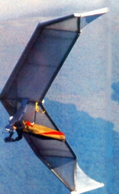
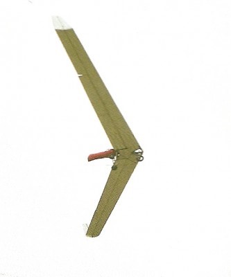
The Flair was a design developed by Günter Rochelt in 1987. Featured on the cover of ‘Drachenflieger’ magazine in November 1987. It was first conceived in 1984, but took some time to develop, with work on the fiberglass – Carbon – Kevlar airframe begun in Spring 1987. After a few test flights, in which the performance was confirmed but the rudders were found to be somewhat ineffectual, Günter decided not to put the Flair into production, concluding that he could improve performance further with some changes to the design (which led to the Flair 30, whose design goal was to reach a 30:1 glide ratio in a foot-launched aircraft.)
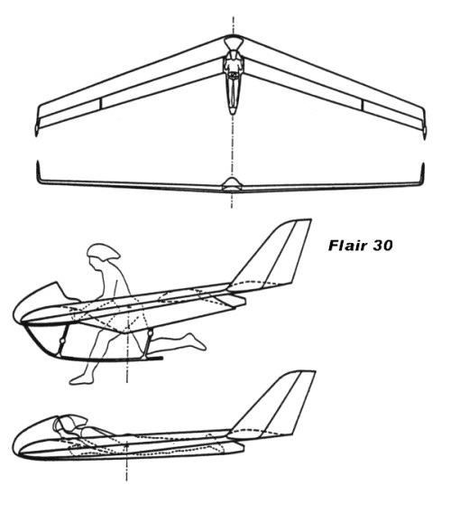
The Flair 30 was a follow-up to the Flair design and first flew in 1990. The pilot could launch by foot, then lay prone in a special harness, and finally land on a skid. After extensive test flights, including more than 50 hours logged by test pilot Knut Von Hentig, the prototype was destroyed in a crash at a sailplane club, when the sailplane pilot flying it dove into the ground at high speed from less than 100 m. Control reversal was suspected but unproved.
Flair 30
The test pilot felt the glide ratio and sink rate was quite poor, worse actually than modern flex wings
Flair Wing area: 14.5 m² Wing span: 11.47 m Aspect ratio: 9 Maximum pilot weight: 165 kg Max glide ratio (L/H): 17 Max glide ratio speed: 45 km/h Minimum sink rate: 0.65 m/s Nose angle: 147°
Flair 30 Wing area: 11 m² Wing span: 12 m Aspect ratio: 14 Profile: CM-140-K47 Hang glider weight: 33 kg Maximum pilot weight: 90 kg Minimum speed: 30 km/h Maximum speed: 150 km/h Max glide ratio (L/H): 30 Max glide ratio speed: 65 km/h Minimum sink rate: 0.72 m/s Packed length: 6.6 m Nose angle: 160°