Rolls-Royce Condor

Condor I

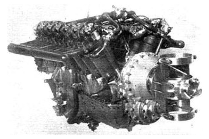
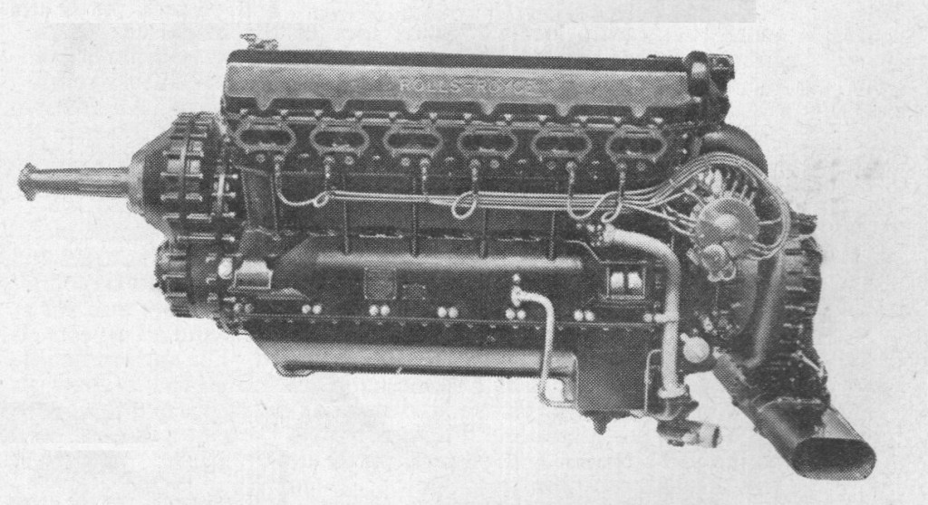
When it first appeared, in August 1918, the Condor followed very closely the pattern of the Falcon and Eagle, though it was of larger (35 litres) capacity. The Condor Series I was designed for 550/600 h.p., and the larger cylinders necessitated four valves per cylinder instead of two. The valves on each bank were operated by a single camshaft. There were only two carburettors and these were mounted low down on each side of the crankcase in line with the centre bearing. The water pump was transferred to the centre of the engine and an electric starter could be provided.

In succession to the Series I came the IA, wherein the normal output was raised to 650 h.p. at 1,900 r.p.m. There is no record of the Condor II but the Series III, which differed considerably from its predecessors, developed 650 h.p. at 1,900 r.p.m., though it weighed nearly 300 lb less. The Series III was fitted with a single-spur reduction gear, carried in a housing bolted to the front end of the crankcase. This changed the outline of the engine and made for improved cowling lines. The makers nevertheless recognized that higher stresses were set up in the crankcase than with the old epicyclic type. In the new gear a flange was formed on the front end of the camshaft and to this was bolted an internally toothed ring, the teeth of which engaged with similar teeth on the end of a short hollow shaft. The opposite end of the shaft was formed with splines to transmit the torque to a hollow pinion mounted in roller bearings. Thus, any transverse loads were prevented from being transmitted to the crankshaft from the gearing. The pinion engaged with a toothed wheel mounted on, and keyed to, the airscrew shaft, which was supported on roller bearings and was fitted with a ball-and-thrust bearing to take the thrust of the airscrew. The engine was cleared to use a metal airscrew and an efficient diameter was about 16ft.

Another point of difference between the Condor and the earlier Rolls-Royce engines was in the design of the connecting rod assembly: in the former engines articulated rods had been used, the Condor had forked rods.

Condor III

Engines of the Condor III series varied from one another in certain respects, but an Air Ministry description in a publication of 1926 remarks that the various pumps serving the engine had been built into a single unit bolted beneath the crankcase lower half. This unit comprised three oil pumps, a water pump and a petrol pump, the last-named being a unit not previously fitted to any Rolls-Royce engine as a standard component. The description went on: “the carburettor has been redesigned and the altitude control valve is of an entirely new design. Owing to the desire to reduce weight, no hand starting device has been provided, but provision has been made for starting by means of the Bristol gas starter. To this end a gas distributor is provided and is driven from the mechanism contained in the wheelcase.”

The Condor IV was a direct-drive engine intended for fighters, and was extensively flown in the Hawker Hornbill, the fastest fighter of its day. The absence of the reduction gearing saved about 80 lb in weight. Normal output was 650 h.p. at 1,900 r.p.m., and dry weight 1,250 lb.

An experimental Condor was fitted with a turbo supercharger running at 26,000 r.p.m., and giving an induction pipe pressure of 13.5 lb/sq in at a height of 2,000 ft. It was never flight tested. The Series VIII, specially designed for internal installation in a projected Supermarine flying-boat, was another development which was not air-tested.

During 1932 it was announced that a compression-ignition version of the Condor had passed the Air Ministry’s civil-engine type test of 50 hr and that flight trials were then under way at Farnborough in a Hawker Horsley. The C.I. Condor gave 500 h.p. and weighed, with spares and accessories, 1,504 lb. Conversion was initiated by the Air Ministry and the engine was developed at the Royal Aircraft Establishment with the co-operation of Rolls-Royce, Ltd.

British aircraft powered with the Condor included the Beardmore Inflexible, Avro Aldershot, Ava and Andover, Blackburn Iris I. II and III, D.H. Derby, Fairey Atalanta, Titania and Fremantle, Handley Page Handcross, Hawker Horsley, SaundersRoe Valkyrie, Short Cromarty and Singapore, Vickers Vixen and Vanguard, and Westland Yeovil.

A total of 327 engines were recorded as being built.
In 1932 the Air Ministry initiated a conversion of the Condor petrol engine to the compression ignition system. The conversion was developed at the Royal Aircraft Establishment, Farnborough, with the co-operation of Rolls-Royce Ltd. Engine layout, bore, and stroke remained the same as for the petrol version; the compression ratio increased to 12.5:1. The more robust construction required to withstand the increased stresses increased the engine weight to 1,504 lbs (682 kg). At its maximum 2,000 rpm the engine developed 500 hp (373 Kw), giving a power/weight ratio of 0.33 hp/lb.
The engine passed the 50-hour civil type test for compression ignition engines, being only the second British engine to do so. The only previous engine to pass this test was the much larger Beardmore Tornado fitted to the R101 airship. The diesel Condor was experimentally flown in a Hawker Horsley to explore the practical operation of a diesel engine in flight.

Variants:
Condor I
(1920-1921) 600 hp, 72 built at Derby.

Condor IA
Alternative designation for Condor II.

Condor II
(1921) 650 hp, revised propeller reduction gear ratio, increased compression ratio (5.17:1). 34 built at Derby.

Condor III
(1923-1927) 650/670 hp, compression ratio 6.5:1, Re-designed connecting rods. 196 built at Derby.

Condor IIIA
(1925) 650/665 hp. Improved main bearing design and material.

Condor IIIB
(1930) 650 hp, 0.477:1 reduction gear, re-designed crankcase and crankshaft.

Condor IV
(1925) 750 hp. Direct-drive, modified engine mounting. 13 built at Derby.

Condor IVA
(1927) 750 hp. Nine built at Derby.

Condor V
(1925) As Condor IIIA with two-stage turbocharger. Run but not flown, one built at Derby.

Condor VII
Direct-drive Condor IIIA, two built at Derby.

Condor C.I.
(1932) 480 hp, compression ignition (diesel), two engines tested and flown.

Applications:
Avro Aldershot
Avro Andover
Avro Ava
Beardmore Inflexible
Blackburn Iris
Bristol Berkeley
de Havilland DH.27 Derby
de Havilland DH.54 Highclere
de Havilland DH.14 Okapi
Fairey Fremantle
Fairey N.4
Handley Page Handcross
Hawker Hornbill
Hawker Horsley
R100
Rohrbach Ro V Rocco
Saunders Valkyrie
Short Singapore
Vickers Valentia
Vickers Vanguard
Vickers Vixen
Vickers Virginia
Westland Yeovil

Specifications:
Condor III
Type: 12-cylinder liquid-cooled 60 deg. Vee aircraft piston engine
Bore: 5.5 in (139.7 mm)
Stroke: 7.5 in (190.5 mm)
Displacement: 2,137.5 in³ (35.03 L)
Length: 69.3 in (1,760 mm)
Width: 41.1 in (1,044 mm)
Height: 43.2 in (1,097 mm)
Dry weight: 1,380 lb (628 kg)
Valvetrain: Overhead camshaft
Fuel system: 2 x Claudel-Hobson carburettors
Fuel type: Petrol
Cooling system: Liquid-cooled
Power output: 670 bhp (500 kW) at 1,900 rpm
Compression ratio: 5.1:1
Rolls-Royce RB.39 Clyde

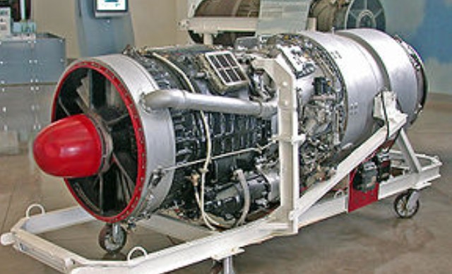
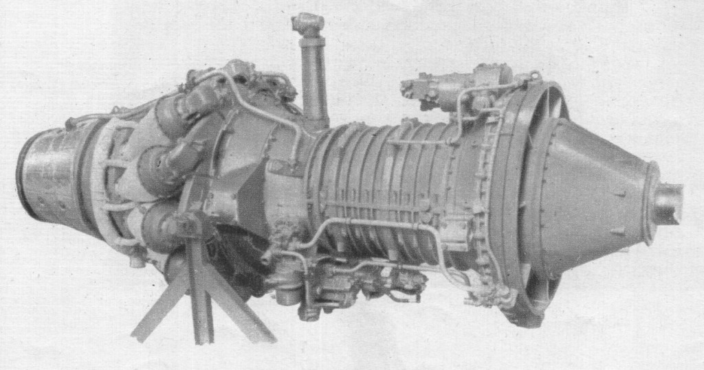
The RB.39 Clyde was Rolls-Royce’s first purpose-designed turboprop engine, first run on 5 August 1945.

The Clyde used a two-spool design, with an axial compressor for the low-pressure section, and a single-sided centrifugal compressor as the high-pressure stage, running on concentric shafts. It had a nine-stage axial compressor and a single-stage centrifugal compressor, in addition to two turbines. The forward (high-pressure) turbine drove the centrifugal blower, and the rear (low-pressure) turbine the axial compressor and contra-rotating airscrews.

The Clyde was the first turboprop to pass its full civil and military type-tests. Its first tests were run at 2,500 s.h.p. and this was later increased to 3,020 s.h.p. Subsequent ratings were 3,500 e.h.p., 4,200 s.h.p. and 4,500 e.h.p.; these last proved that the reduction gear was capable of standing greatly increased overloads.

The Clyde was a long engine with the axial LP compressor in front of what was, in effect, a scaled down Derwent engine. Accessories were grouped around the axial compressor which conveniently narrowed towards the rear. Cooling for turbines and turbine bearings came from a small diffuser on the main shaft as well as tappings from the axial and centrifugal compressors. Testing of the development engines exceeded expectations with the engine soon being rated at 4,030 eshp. One problem un-earthed during testing was that damaging resonances emanated from the straight-cut spur gears in the reduction gearbox.

The 4,030 eshp versions were selected as the main engine of the Westland Wyvern TF Mk.2 strike aircraft.

Despite the promising performance of the test engines Ernest Hives felt that pure-jets were the future and the Clyde programme was terminated with only 9 built, forcing Westlands to use the less than satisfactory Armstrong Siddeley Python on the production Wyverns.

Clyde
Type: Twin-spool turboprop
Length: 10.1 ft (3.08 m)
Diameter: 3.9 ft (1.19 m)
Dry weight: 2,800 lb (1,300 kg)
Compressor: LP – 9 stage axial, HP – Single centrifugal stage
Combustors: Eleven can-type combustion chambers
Turbine: HP – single stage axial, LP – single stage axial
Fuel type: Kerosene (jet fuel grade)
Oil system: Pressure spray scavenge system
Maximum thrust: 1,225 lbf (5.45 kN)
Overall pressure ratio: 6:1
Specific fuel consumption: 0.71 lb/hp/hr (0.24 kg/kW/hr)
Power-to-weight ratio: 1.43 hp/lb (2.08 kW/kg)

Rolls-Royce Buzzard / H Srs

The Rolls-Royce Buzzard (also referred to as the H engine) was a British piston aero engine of 36.7 litres (2,240 cubic inch) capacity that produced about 800 horsepower (600 kW). The Buzzard was developed by scaling-up the Kestrel engine in the ratio of 5:6. Designed and built by Rolls-Royce Limited it featured 12 cylinders in a ‘V’ configuration of 6 inch bore and 6.6 inch stroke, and the engine was supplied as standard with a medium supercharger capable of being used to its fullest extent on the ground, so as to give the maximum possible take-off power, first run in June 1928.

The Series I, II and III engines had reduction gear ratios of 0.632, 0.553 and 0.477 respectively, and the normal power was 825 h.p. at 2,000 r.p.m. at sea level. At 2,300 r.p.m., 955 h.p. was available at sea level. The dry weight was 1,540 lb.

Buzzards were installed in the Blackburn Iris V and VI (Perth), MA/30 and MA/30A, Handley Page H.P.46 (MA/30), Hawker Horsley, Short Singapore I, K.F.I and Sarafand, and Vickers M.1/30.

The total production of Buzzard engines 100.

It was manufactured in the late 1920s, but only 100 were sold. A further development was the Rolls-Royce R Schneider Trophy engine.

Variants:
Buzzard IMS, (H.XIMS)
(1927), Maximum power 955 hp (712 kW), nine engines produced at Derby.

Buzzard IIMS, (H.XIIMS)
(1932-33), Maximum power 955 hp (712 kW), reduced propeller drive ratio (0.553:1), 69 engines produced at Derby.

Buzzard IIIMS, (H.XIVMS)
(1931-33), Maximum power 937 hp (699 kW), further reduced propeller drive ratio (0.477:1), 22 engines produced at Derby.

Applications:
Blackburn Iris
Blackburn M.1/30
Blackburn Perth
Handley Page H.P.46
Hawker Horsley
Kawanishi H3K
Short Sarafand
Vickers Type 207

Specifications:
Buzzard IMS
Type: 12-cylinder liquid-cooled Vee aircraft piston engine
Bore: 6 in (152.4 mm)
Stroke: 6.6 in (167.6 mm)
Displacement: 2,239.3 in³ (36.7 L)
Length: 75.7 in (1,923 mm)
Width: 30.6 in (777 mm)
Height: 44.4 in (1,128 mm)
Dry weight: 1,140 lb (517 kg)
Valvetrain: Overhead camshaft
Supercharger: Single-stage supercharger
Fuel type: 73-77 octane petrol
Cooling system: Liquid-cooled
Power output: 800 hp (600 kW)
Specific power: 0.36 hp/in³ (16.3 kW/L)
Compression ratio: 5.5:1
Power-to-weight ratio: 0.7 hp/lb

Rolls-Royce Avon / Svenska Flygmotor RM5 / RM6 / Westinghouse XJ54

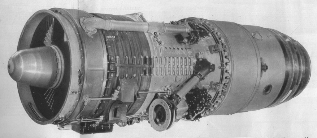
The Avon design team was headed by Cyril Lovesey, who had previously been in charge of Merlin development. The engine was intended both as an experiment in axial-flow turbojet engines, as well as (if successful) a replacement for the 5,000 lbf (22 kN) Nene. Originally known as the AJ.65 for Axial Jet, 6,500 lbf which was originally designed by Alan Arnold Griffith, the engine developed as a single-spool design with an eight, later 10 stage compressor, mass flow rate of 150 lb/s (68 kg/s) and a pressure ratio of 7.45. Development started in 1945 and the first prototypes were built in 1947.

The main series of the Avon were the 1 and 100 Series and the 200 Series. The I and 100 series have a similar axial flow compressor, while the 200 Series has a axial flow compressor with additional stages. In the 1 and 100 Series the combustion assembly consists of eight flame tubes in individual casings, but the 200 Series has flame tubes contained in an Annular casing.

The first bench testing of the Avon took place early in 1947. The first production version was running during 1949. In 1951, the first engines of the 100 and 200 Series were bench tested.

The take-off thrust of the Avon I was 6,500 lbs. Development of material allowed increased operating temperatures and when the 100 Series was introduced the thrust was 7,500 lb.

Introduction was somewhat slowed by a number of minor problems. The first Avons to fly were two Avon RA.2s in the converted Lancastrian military serial VM732, which flew from Hucknall on August 15, 1948. The prototype RA.2 weighed 2,400 lb and gave 6,000 lb thrust, while the production RA.3 was 125 lb lighter.

Initially a private venture for the company, government backing was forthcoming around the time of the first prototypes.

The engine eventually entered production in 1950, the original RA.3/Mk.101 version providing 6,500 lbf (29 kN) thrust in the English Electric Canberra B.2. Similar versions were used in the Canberra B.6, Hawker Hunter and Supermarine Swift.

The 200 Series began with 9,500 lb thrust and was soon 11,250 lb.

Uprated versions soon followed, the RA.7/Mk.114 in 1952, producing 7,350 lbf (32,700 N) in the de Havilland Comet C.2, the RA.14/Mk.201 of 9,500 lbf (42 kN) in the Vickers Valiant and the RA.26 of 10,000 lbf (44 kN) used in the Comet C.3 and Hawker Hunter F.6.

The first of the series with all-weather protection, the RA.7 had a power/weight ratio even better than that of the original production engines, notwithstanding the fact that it had been restressed to accept the loads imposed at transonic speeds. The RA.7R (the suffix “R” denotes that reheat, or afterburning, is fitted) delivers 9,500 lb static thrust at sea level, and an offshoot of the same family is the civil 500 Series, the 503 being the engine of the Comet 2.

Avon RA.14

The Avon RA.14 first ran in 1952. It has a longer compressor than its forerunners, and it also has a true annular combustion chamber in order to accept the tremendous mass flow without increasing “hoop” diameter. The R.A.14 was intended for installation in the wing (it is known that it powers the Vickers-Armstrongs Valiant B.1), and every effort has been made to reduce depth to a minimum.

Originally the Avon was made as a military engine but, in February 1952, the first flight in a civil aircraft was made. A civil counterpart is the RA.16 of 9,000 lb thrust, which was originally intended to power the Comet 3, though that aircraft had later variant, giving 10,000 lb thrust.

An Avon-powered de Havilland Comet 4 flew the first scheduled transatlantic jet service in 1958.

The modifications and improvements introduced to the Avon 200 series were considerable, resulting in a completely different engine with very little in common with the early Marks. Despite this, the name Avon was retained. Differences included a completely new combustion section, a 15 stage compressor based on that of the Armstrong-Siddeley Sapphire, as well as other improvements.

The line eventually topped out with the 12,690 lbf (56,450 N) and 16,360 lbf (72,770 N) in afterburner RA.29 Mk.301/2 (RB.146) used in later versions of the English Electric Lightning. Other aircraft to use the Avon included the de Havilland Sea Vixen, Supermarine Scimitar and Fairey Delta.

Avon RA29

The Avon was also produced under license by Svenska Flygmotor as the RA.3/Mk.109 as the RM5, and an uprated RA.29 as the RM6 with 17,110 lbf (76,110 N). The RM5 powered the Saab Lansen, while the RM6 was the main powerplant of the SAAB Draken.

Production was also carried out in Belgium by Fabrique Nationale, including 300 Avon 113s, and a larger number of Avon 203s.

In the US, the Avon was used to power the vertical landing Ryan X-13 Vertijet aircraft (in RA.28-49 form).

In Australia, the Avon was used by Commonwealth Aircraft Corporation to power its heavily modified variant of the F-86 Sabre, known as the CA-27 Avon-Sabre.

The Avon continued in aero engine production, mostly for the use in the Sud Aviation Caravelle and English Electric (BAC) Lightning, until 1974, by which time over 11,000 had been built. The engine garnered an impressive safety record over that time. The Avon remained in operational service with the RAF, powering the English Electric Canberra PR.9, until 23 June 2006.

The Avon 200 is an industrial gas generator that is rated at 21-22,000shp. As of 2011, 1,200 Industrial Avons have been sold, and the type has established a 60,000,000 hour class record for its class.

Variants:
AJ65
The original designation, standing for Axial Jet 6,500lbs thrust

RA.1
Prototype engines for testing and development.

RA.2
Pre-production engines for testing. 6,000 lbf (26.69 kN)

RA.3
Civil designation for the first Avon production mark – 6,500 lbf (28.91 kN).

RA.7
Civil designation for the uprated version of the Avon. – 7,350 lbf (32.69 kN).

Mk.114
Military designation for the RA.7 Avon – 7,350 lbf (32.69 kN)

RA.14
Civil designation for the uprated version of the Avon with can-annular combustion chamber and Sapphire style compressor – 9,500 lbf (42.26 kN).

RA.21
8,050 lbf (35.81 kN) Production engine developed from the RA.7.

RA.24

RA.26
Further improvements to the Avon 200 series

RA.28
Second generation variant 10,000 lbf (44.48 kN)

RA.29
Civil designation for the Mk.300 series (used by the Sud Aviation Caravelle)

RA.29/1

RA.29/3

RA.29/6

Mk.100 series
Military designation for the RA.3 Avon – 6,500 lbf (28.91 kN).

Mk.200 series
Military designation for the uprated version of the Avon with can-annular combustion chamber and Sapphire style compressor – 9,500 lbf (42.26 kN).

Mk.300 series
Developed after-burning engines for the English Electric Lightning.
RB.146 Mk.301:The ultimate Military Avon for the English Electric Lightning – 12,690 lbf (56.45 kN) dry, 16,360 lbf (72.77 kN) wet.

RB.146 Mk.302:Essntially similar to the Mk.301

Avon 504
Civilian equivalent to military Mk.200 variants.

Avon 506
Civilian equivalent to military Mk.200 variants.

Avon 522
Civilian equivalent to military Mk.200 variants.

Avon 524
Civilian equivalent to military Mk.200 variants.

Avon 524B
Civilian equivalent to military Mk.200 variants.

Avon 525
Civilian equivalent to military Mk.200 variants.

Avon 525B
Civilian equivalent to military Mk.200 variants.

Avon 527
Civilian equivalent to military Mk.200 variants.

Avon 527B
Civilian equivalent to military Mk.200 variants.

Avon 531
Civilian equivalent to military Mk.200 variants.

Avon 531B
Civilian equivalent to military Mk.200 variants.

Avon 532R
Civilian equivalent to military Mk.200 variants.

Avon 532R-B
Civilian equivalent to military Mk.200 variants.

Avon 533R
Civilian equivalent to military Mk.200 variants.

Avon 533R-11A
Civilian equivalent to military Mk.200 variants.

Svenska Flygmotor RM5
Licence production of the RA.3/Mk.109 for the Saab 32 Lansen

Svenska Flygmotor RM6
Uprated RA.29/Mk.300 for the Saab Draken

Westinghouse XJ54
Version of Avon intended to be produced/sold by Westinghouse in the US

Applications:
Military aviation:
CAC Sabre
de Havilland Sea Vixen
English Electric Canberra
English Electric Lightning
Fairey Delta 2
Hawker Hunter
Ryan X-13 Vertijet
Saab 35 Draken
Saab Lansen
Supermarine Swift
Supermarine Scimitar
Vickers Valiant

Civil aviation:
de Havilland Comet
Sud Aviation Caravelle

Other uses:
The Avon is also currently marketed as a compact, high reliability, stationary power source. As the AVON 1533, it has a maximum continuous output of 21,480 shp (16.02 MW) at 7,900 rpm and a thermal efficiency of 30%. In 1982, an Avon engine on gas pumping duty in a Canadian installation ran for 53,000 hours before requiring a major overhaul. In 1994, another industrial Avon engine ran non-stop for 476 days (11,424 hours).

As a compact electrical generator, the type EAS1 Avon based generator can generate a continuous output of 14.9 MW.
On 4 October 1983, Richard Noble’s Thrust2 vehicle, powered by a single Rolls-Royce Avon 302 jet engine, set a new land-speed record of 1,019.46 km/h (633.46 mph) at the Black Rock Desert in Nevada.

Specifications:
Avon 301R
Type: Turbojet
Length: 126 in (3,200 mm)
Diameter: 35.7 in (907 mm)
Dry weight: 2,890 lb (1,310 kg)
Compressor: 15-stage axial flow
Combustors: Cannular, 150 lb/s (68 kg/s)
Turbine: Two-stage axial flow
Fuel type: Kerosene
Maximum thrust: 12,690 lbf (56.4 kN)dry/16,360 lbf (72.8 kN) with reheat
Overall pressure ratio: 7.45:1
Specific fuel consumption: 0.932 lb/(lbf·h) or 26.4 g/(kN·s) (dry) 1.853 lb/(lbf·h) or 52.5 g/(kN·s) (wet)
Thrust-to-weight ratio: 5.66:1 (56 N/kg)

Rolls-Royce

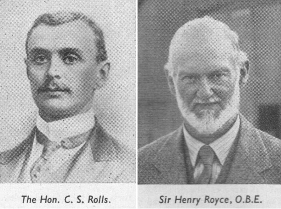
Rolls and Royce, met in Manchester in 1904. Rolls-the Hon. Charles Stewart Rolls-possessed wealth, an Eton-and-Cambridge education, a degree in mathematics and applied science, and a fine record as a motorist. He was a sportsman he had consistently displayed a daring at the wheel and a determined approach to the technical problems of motoring.

In the business of C. S. Rolls and Co., which he established with Claude Johnson in 1902. In 1903 he set a world speed record of 93 m.p.h.; but the car was a 70 h.p. Mors, and by the following year, when his books showed orders for a hundred Continental cars, he could still not find a British product which measured up to his standards.

At ten years of age Henry Royce started work as a telegraph boy, later attending a technical college, and serving a few years in the Great Northern locomotive shops at Peterborough. After a spell in an engineering works at Leeds, he set up a business in Manchester, making arc lamps and dynamos. The slump after the Boer War caused him to turn his ambition to cars. Disappointed with a foreign model which he acquired, he decided to put his own ideas into practice, and in 1903 he completed a two-cylinder car of 10 h.p., having handled much of the precision work himself.

One of his first three cars went to Henry Edmunds, who arranged the meeting in Manchester. The two men took to each other immediately, and having tried out Royce’s car, young Rolls undertook to sell its maker’s entire output. But he began to ply his partner with suggestions and demands.

The “two Rs” were first officially linked in business association at Christmas 1904, by a working agreement between the two firms; and thenceforth the Rolls-Royce car began.

By 1906 Royce’s production was large enough to allow Rolls to stop his sales of other makes of car, and Rolls-Royce, Ltd., was founded. Royce’s old partner, A. E. Claremont, became chairman; Rolls was technical managing director; and Royce was nominated chief engineer and works director.

Charles Stewart Rolls

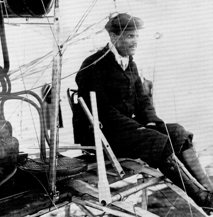
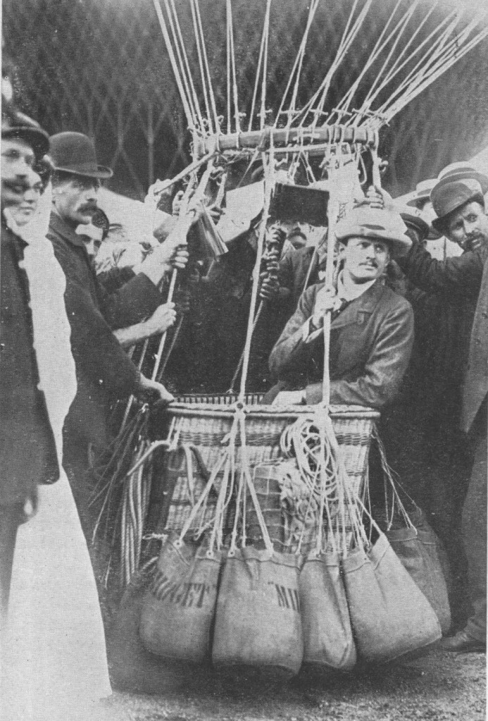
Rolls, who had become a member of the Aeronautical Society in 1901, was already a keen balloonist; then, having met the Wright brothers, he turned to heavier-than–aircraft. He was awarded his pilot’s certificate (No. 2) on March 8th, 1910-the very same day that Lord Brabazon received his No. 1. On the Wright biplane he made the first heavier-than-air crossing of the Channel by an Englishman, and the first double crossing by any aeroplane in history; but soon afterwards-on July 12th, 1910, he crashed to his death at the Bournemouth flying meeting, only 33 years of age. He was the first Englishman to die in an accident to a powered, heavier-than-air machine. His Wright Flyer broke up at 20 ft agl and he cracked his skull.

C.S. Rolls

In 1910 Royce became seriously ill and thereafter was absent for long periods from his new factory at Derby. He worked on in the south of France and on the south coast of England.

Following the British Schneider victory of 1929-made possible by the “R” engine-a baronetcy was conferred upon him, and he heard from his bed how an improved engine of this type sent a Supermarine S.6B to final victory in the Schneider Race of 1931. He died on April 22nd, 1933.

1914 Design of first Rolls-Royce aero engine-later named Eagle started. Company making engines of official pattern at Derby.

1915 Eagle on test six months after design initiated. Hawk
designed and developed. Falcon designed

1918 Condor on test at 525 h.p.

1919 Alcock and Brown, in a Vickers Vimy (two Rolls-Royce Eagle Vills), mode first direct crossing of North Atlantic; flying time, 16 hir 12 min. Ross Smith and Keith Smith, in an Eagle-Vimy, made first flight from England to Australia11,130 miles in 124 hr flying time.

1920 Van Ryneveld and Quintin Brand, also in an Eagle-Vimy, made first flight from England to South Africa-6,281 miles in 92 hr 58 min flying time.

Between 1915 and 1924 Rolls-Royce Aero-engine production was: Eagle, 4,674; Hawk, 200; Falcon, 2,185; Condor, 327.

1925 Design of Rolls-Royce “F” series of engines (later called
Kestrel) started.

1926 First “F” engine tested and delivered.

1927 The ” H ” engine-later the Buzzard-under development.

1929 Air Ministry decided in February to compete in Schneider Trophy Contest; Rolls-Royce asked to develop a racing engine. Within six months “R” engine was delivering 1,900 h.p. for a weight of 1,350 ]b. Installed in Supermarine S.6, which won Schneider Contest at 328.63 m.p.h.

1931 Rolls-Royce again asked to develop a Schneider Trophy engine to help secure a third victory, which would gain Trophy outright for Gt. Britain. Outcome was improved “R” engine of 2,360 h.p., weighing 1,630 lb. Schneider Trophy won outright. Later “R” engine gave 2,530 h.p. and enabled world speed record to be raised to 407.5 m.p.h.

By 1931, during the Great Depression, Bentley was having financial difficulties. When funds ran out in 1931, the receivers were negotiating with D.Napier & Sons Ltd for the sale of the remains of Bentley. However, Rolls-Royce put in a secret bid through a Liechtenstein company, and secured Bentley Motors for £125,256. For this, Rolls-Royce got the factory equipment, a number of incomplete car chassis, and the services of Walter Bentley for three years.

1932 Design of the P.V.12 engine (later called Merlin) started.
(P.V. denoted private venture.)

1934 Merlin completed its first 100 hr run at 790 h.p.

1936 Merlin completed Service Type Test at 975 h.p.

1938 Building of Crewe factory started.

1939 First Merlin built at Crewe. Design and development work
started on 37.V.12 engine, later named Griffon. Building of
Glasgow factory begun in August. 1

1940 First Merlin built at Glasgow. First test run of Griffon.

1942 Quantity production of Griffon started.

1943 First Rolls-Royce turbojet-the Welland-passed its 100 hr type test; thrust, 1,700 lb, weight, 850 lb. Design of Derwent 1 started.

1944 Deliveries of Welland begun, for installation in Gloster
Meteor. Design and development of Nene started.

1945 Meteor powered with Derwent Vs broke world air speed record at 606 m.p.h. In September a Meteor was flown with two Rolls-Royce Trent turboprops, being the first turboprop aircraft to fly. By this year power of Merlin had increased to over 2,000 h.p.

1946 World airspeed record again broken by a Derwent-Meteor;
speed 616 m.p.h.

1947 Pratt and Whitney signed licence agreement for manufacture of Rolls-Royce Nene and Toy. Nenes in production at Derby. Trans-Canada Airlines started operations with Merlin powered Canadair North Stars.

1948 First public appearance ofAvon turbojet at S.B.A.C. Display. Belgium signed licence agreement for manufacture of Derwents.

1949 Dart turboprop type-tested at 1,000 h.p. B.O.A.C. intro-
duced Merlin-powered Argonauts (similar to North Stars).

1950 Australia signed licence agreement to build Nene and Avon.
Hispano signed agreement to make Nene and Toy.

1951 English Electric Canberra, with two Rolls-Royce Avons, made first non-stop transatlantic crossing by a jet aircraft the first of numerous record flights by Avon-Canberras.

1952 Sweden signed licence agreement to build Avon.

1953 Avon-Canberra flew from London Airport to Darwin, Northern Australia, in 22 hr 21 sec. Avon-powered Hawker Hunter established world air speed record of 726.6 m.p.h.; Avon-powered Supermarine Swift later raised record to 735.7 m.p.h. Ministry of Supply opened new factory at East Kilbride, Lanarkshire, to augment production of Avons for the R.A.F. (in addition, Avons were being made by the Bristol Aeroplane Co., Ltd., D. Napier and Son, Ltd., and the Standard Motor Company.)

1954 By May 1954 British-built Rolls-Royce gas turbines had completed 23 million flying hours; Merlins had cornpleted over 5.1 million flying hours in commercial service. By the end of the year over 185,000 Rolls-Royce piston and gas-turbine engines will have been built.

LHTEC (Light Helicopter Turbine Engine Company) is a joint venture between Rolls-Royce and Honeywell founded in 1985. The company was originally a partnership between the Allison Engine Company and AlliedSignal Aerospace . In 1995 Rolls-Royce acquired Allison, and AlliedSignal merged with Honeywell in 1999, and adopted its name.

Rollason Beta

Rollason / Luton Beta B2

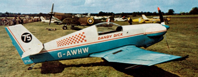
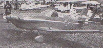
In 1964 Rollasons and the Tiger Club sponsored a competition for a midget racing aircraft which could be used for Formula One air racing. The winner was the Luton Group’s Beta, and after the prototype was attempted by that group, the design was taken over by Rollasons.

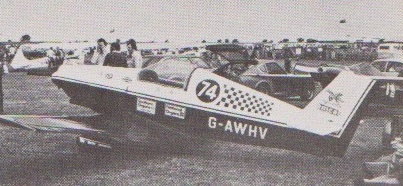
Beta B2A G-AWHV Continental C90

The Beta is a single seat sporting monoplane of all wood construction. The wing employs an NACA23012 aerofoil section and consists of a rectangular centre section and tapered outer panels. The wing is made up of a single main spar and auxiliary rear spar, wood ribs and plywood covering. The mass balanced wooden ailerons are fabric covered. Flaps are optional. The fuselage is a semi-monocoque structure consisting of elliptical wooden frames and plywood covered. The cantilever tail unit has a ply-covered fin and tail plane and fabric covered control surfaces. The fixed undercarriage has rubber in compression shock absorbers on early models, but spring steel legs on later models. Fuel capacity is 10.5 Imperial gallons. Four versions of the Beta are available, the basic difference being the engine fitted.

Beta B4 G-AWHW at Sywell 1975. Continental O-200-A

Beta B1
Engine: Continental A65, 65 hp
Wing span: 20.05 ft
Length: 16.08 ft

Beta B2
Engine: Continental C-90, 90 hp

Beta B2A
Engine: Continental C-90, 90 hp
Undercarriage: spring steel

Beta B3
Engine: Ardem 4C02 Mk.V, 55 hp

Beta B4
Engine: Rolls-Royce 0-200-A, 100 hp
Span: 20’ 5”
Length: l6’8”
Wing Area: 66 sq. ft
Empty Weight: 575 lb
Loaded Weight: 866 lb
Max. Speed: 200 mph
Cruise Speed: 166 mph
Stall Speed: 60 mph (less flaps)
Initial Climb: 1,800 fpm
Range: 300 miles

Rollason

Rollason Aircraft and Engines Ltd.
Initially an aircraft sales and service organization. Began aircraft construction in 1957 with Druine Turbulent single-seat light monoplane powered by a Rollason-converted Ardem motor car engine. Production was carried out at their works on the old Croydon Aerodrome with first flights generally taking place at Redhill.

In 1961 built two-seat Druine Condor with 75 hp Continental engine. Later versions used more powerful Continental engines. Rollason also rebuilt a number of Tiger Moths and other aircraft, and carried out seaplane conversions of the Tiger Moth and Turbulent.

In 1973 the company moved from Croydon to premises at Shoreham. Tiger Moth work was concentrated at Rochester, with Redhill providing back-up to both bases and the hub of the sales part of Rollasons.

Rolladen-Schneider LS 10

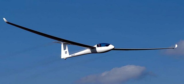
The end of 2005 concluded a series of workshops around key ideas for the new LS10. One key principle was not to “DG-ize” the LS10 but rather maintain the typical LS characteristics.
The LS 10 will differ from the existing model by all LS10 gliders being engine-ready. To simplify production all LS10 gliders will have the engine box built into the fuselage. All LS10 ordered in the glider-only version will offer the option of retrofitting a sustainer engine later.
The typical LS toe brake actuation will be replaced by a drum break actuated by the dive brake lever (in its fully deployed position). The “Haenle” guides for the ailerons remain.

There are no changes to the LS-type elevator assembly, but the outer wing panels trade-in the old threaded bolt for a spring loaded locking pin for easier assembly.

The skids on the wingtips remain (no wheels) as there will be no self-launching version.

All versions of the LS10 feature 4 wing panels, i.e. each wing will be partitioned into two panels for all versions and configurations of the LS10. This design ensures easier assembly and allows for the use of a shorter trailer. As for the location of the paring between inner and outer panels, the further out toward the wing tip the designer places the divide, the easier the assembly and the cheaper and lighter the required connection for the wing spar. In the limit of parting at y=7.25m however, the resulting wing tips of 0.25m for the 15m wing plan form lead to sub-optimal performance characteristics. If the divide is moved too far toward the wing root, the outer panels become so heavy that they cannot be handled by one person. In addition, this also raises the total weight of the wing substantially, which in turn leads to a more expensive overall wing design. The best compromise is for the parting to be at y=7m. This results in 2m outer panels for the 18m version, a size that can still be handled effectively by one person. Combing the resulting 0.5m wingtips for the 15m version with “high” winglets leads to an aerodynamically optimal plan form for this version as well.

The 18m wing plan form will feature the well-known LS curved winglets.

All LS10 gliders are designed to accommodate a bug wiper system. Integrating this option into the design of the LS10 allows for the installation of a lower drag bug wiper system.

Meanwhile the second LS10 was construction at the Bruchsal facility according to the original Rolladen-Schleicher design. This aircrafts construction was begun by Rolladen-Schneider and was suffering from delays due to the well-known legal problems. The test pilot was Micro Scholz.

Its design is still identical to the “original”, as is production no. 1. The design of number 3 is currently being completed. It will include a number of improvements and will serve as the basis for serial production.

In parallel with the flight tests staff worked on detailed solutions and modifications. The extensive testing of the two prototypes resulted in new fairings at the lower part of the vertical fin, but the biggest changes took place in the cockpit e.g. the position of the rudder pedal cavity foot tub was changed. Now there will be room for big feet. To further improve the view out of the cockpit the instrument panel could be further lowered – without loosing space for the instrumentation, and a Piggott-Hook was installed.

The operating forces of the water ballast system were reduced. The shape of the opening levers was optimised. The flap lever the changes in flap setting works more precisely and pilot-friendly – the handle is coated with fine leather. The decompression lever for starting the engine was moved and now is very well accessible. The position of the trim knob was optimized ergonomically and functions much better. The rudder pedal handle now retracts in the seat pan after use in the LS10.

A very tall pilots will fit in the LS10 by using an optional separate headrest which can be installed instead of the back support. The change can be done in a minute.

Span: 15 m
Area: 10.4 sq.m
Aspect ratio: 21.7
Airfoil: Lemke
Empty Weight: 250 kg
Gross Weight: 525 kg
Wing Load: 50.5 kg/sq.m
Seats: 1