Rolls-Royce Flying Bedstead / Thrust Measuring Rig / TMR

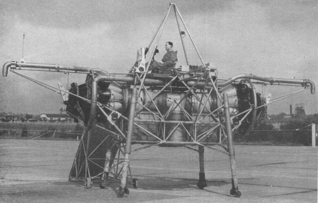
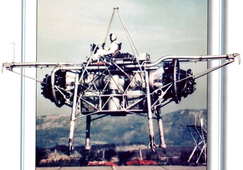
The Bedstead, officially called a Thrust Measuring Rig (TMR), was the brainchild of Doctor A.A.Griffith of Rolls Royce. It was a flat riser which hovered on the deflected exhaust gases of two Rolls Royce Nene jet engines. Compressed air nozzles provided directional control. The data gathered during the Bedsteads’ test programme in the mid 1950s led to the development of a special turbojet engine for jet lift, the RB108.

This was a radically new approach towards the development of vertical take off aircraft. Basically it consists of a tubular frame, said to measure about 20 ft. across, on which are mounted two Nene engines having a common, downward facing tail pipe. Space is also provided for fuel tankage and the pilot is seated in the normal attitude on the top.

The weight amounts to some 3.5 tons, and is a little less than the total maximum thrust from the 5,000 lb. thrust Nenes. The two engines are mounted horizontally, facing away from each other, the exhaust gases being turned through 90 degrees to enter a common downward directed tail pipe. The thrust so obtained provides for direct vertical jet lift of the rig.

Control in the pitch, roll and yaw planes is obtained by means of air jets bled from the Nene compressors. No aerodynamic control surfaces are used.

Capt. R.T. Shepherd, who was Rolls Royce’s chief test pilot until 1951, made the first fully free flight trials on August 3, 1954. During the previous 12 months or so, the ” jet lifter ” had undergone tethered flights, the amount of tethering being progressively relaxed as more experience was gained. The rig has since also been flown by Mr. H. Bailey, the company’s chief test pilot, and Sqn. Ldr. Harvey, of the R.A.E.

Flights have been made involving hovering and sideways and vertical movement. Landing is said to be very light and incurs no sudden drop. As with a helicopter, horizontal motion is produced by tilting the lift component, in this case from the propulsive jet, and a horizontal as well as a vertical thrust is obtained in this way.

Its pilot sat on a control station atop an entirely open-air framework of tubing, a calliope of ‘puff-pipes’ for attitude control arranged all around him. It was nicknamed the ‘Flying Bedstead’. NASA were interested in its reaction control system for their lunar lander simulator.

Pilot Capt. Shepherd

Rolls-Royce Falcon

Falcon III

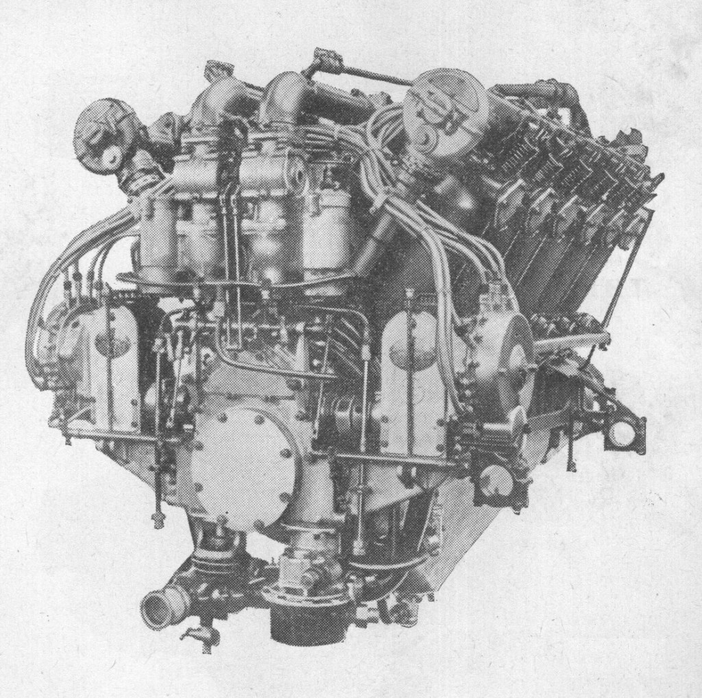
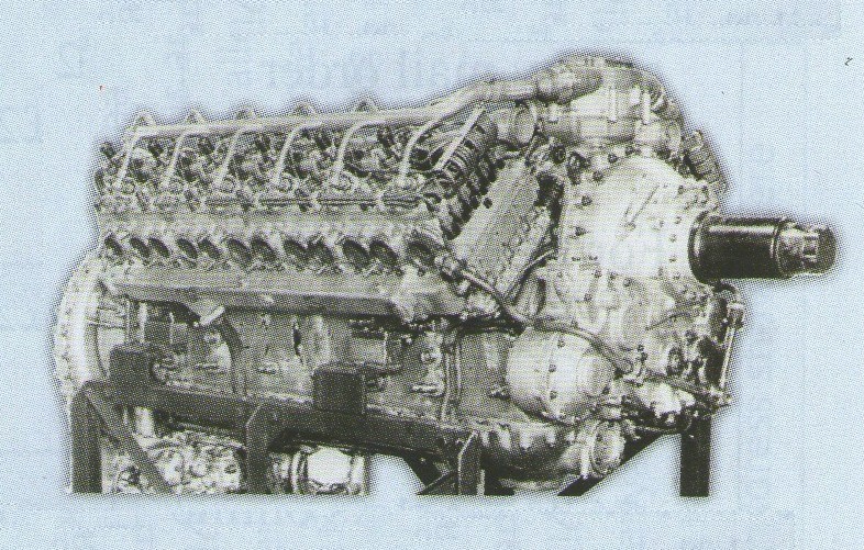
In April 1916 came the Falcon-virtually a scaled~down Eagle. Again ratings increased and in April 1916 the figure was 205 h.p.; in May, 228 h.p.; in February 1917, 247 h.p.; and in April 1917, 262 h.p, all at 1,800 r.p.m. By November 1917 the output had risen to 278 h.p. and by July 1918 to 285 h.p.-in both instances at 2,000 r.p.m. Official data for the Falcon I were: weight, 650 lb; b.h.p. at normal r.p.m., 228; fuel consumption (gal/hr), 16.6. Corresponding figures for the Falcon II were: 665. 255, 18.25, and for the Falcon III (by far the most famous member of the family) 660, 270, and 18.75.

An unusual feature of this engine is the epicyclic propeller reduction gear which contains a clutch designed to limit the maximum torque, thus protecting the reduction gears.

Constructional particulars for the Eagle VIII apply generally to the Falcon III. First run in 1915, production of the Falcon began in September 1916 and was so successful that it was also manufactured under licence by Brazil Straker in Bristol. Production continued until 1927, by which time 2,185 had been built.

The best-known application of the Falcon was to the Bristol Fighter F.2B, wherein the Series Ill engine became standard and remained in service until the 1930s. Other British military installations were made in the Martinsyde F.1, F.3 and F.4, R.E. 6 and 7, Armstrong Whitworth F.K.12, Avro 523C and 529 Pike, Blackburn S.P. and G.P. seaplanes, Kangaroo and Sprat, D.H.4, Fairey F.2, Sopwith tractor triplane, Parnall Perch, improved Short 184, and Vickers Vendace.

Production ceased in 1927 after 2,185 were built. The unit cost in 1918 was £1,210.

Rolls-Royce Falcon III

Variants:
Falcon I (Rolls-Royce 190 hp Mk I)
(1916-17), 230 hp, 250 engines produced in both left and right hand tractor versions.

Falcon II (Rolls-Royce 190 hp Mk II)
(1917), 253 hp, carburettor size increased. 250 built at Derby.

Falcon III (Rolls-Royce 190 hp Mk III)
(1917-1927), 285 hp, increased compression ratio (5.3:1), twin carburettors replaced with four Rolls-Royce/Claudel-Hobson units. 1,685 built at Derby.

Applications:
Armstrong Whitworth F.K.12
Avro 523C Pike
Avro 529
Blackburn G.P. Seaplane
Blackburn Kangaroo
Blackburn Sprat
Bristol Type 12 F.2A
Bristol Type 27 F.2B Coupe
Bristol F.2 Fighter
Bristol Type 86 Greek Tourer
Bristol Type 96
de Havilland DH.37
Fairey F.2
Fairey N.9
Martinsyde F.3
Martinsyde R.G
Martinsyde Buzzard
Parnall Perch
Royal Aircraft Factory F.E.2
Royal Aircraft Factory R.E.7
Vickers F.B.14
Vickers Viking
Vickers Vendace
Vickers Vedette
Westland Limousine
Westland Wizard

Specifications:
Falcon III
Type: 12-cylinder liquid-cooled 60 deg. Vee aircraft piston engine
Bore: 4 in (101.6 mm)
Stroke: 5.75 in (146 mm)
Displacement: 866.5 in³ (14.2 L)
Length: 68 in (1,727 mm)
Width: 40.3 in (1,024 mm)
Height: 37.2 in (945 mm)
Dry weight: 715 lb (324 kg)
Valvetrain: Overhead camshaft, two valves per cylinder
Fuel system: Four Rolls-Royce/Claudel-Hobson carburettors
Fuel type: 40-50 octane petrol (pre-1923)
Cooling system: Liquid-cooled
Power output: 288 hp (215 kW) at 2,300 rpm at sea level
Compression ratio: 5.3:1
Fuel consumption: 18.5 Imp gal/hr (84 L/hr)
Oil consumption: 0.75 Imp gal/hr (3.4 L/hr)
Power-to-weight ratio: 0.4 hp/lb (0.66 kW/kg)

Rolls-Royce XVI / X-16

The appearance of the Curtiss D-12, and its importation under license to Britain by Fairey prompted the Air Ministry to ask Rolls-Royce to develop a new aero engine for fighter aircraft, the ministry felt that there were too many engine manufacturers and did not support or encourage the Fairey company to continue. Rolls-Royce developed two distinct types of engine to meet the requirement, the F engine, which became the Kestrel, and the Eagle XVI.

Designed by Henry Royce, the Eagle XVI was a completely new design and unrelated to the earlier Eagle. The engine featured four banks of fore and aft staggered cylinder blocks with the banks arranged at 90 degrees to each other to form a perfect ‘X’. The valve gear was operated by a single overhead camshaft and used four valves per cylinder. The crankcases and cylinder blocks were cast from aluminium alloy. Normal engine bearers could not be used so the unit was held in the test stand by two conical mounts that attached to the crankcase.

Initial test running was carried out in 1925 without a supercharger fitted and an improvised carburettor and induction system. The engine did not run well with this arrangement due to poor fuel distribution, however when a supercharger and matched carburettor were fitted (borrowed from the Kestrel development unit) the engine ran and performed well, producing 500 hp (373 kW) on the dynamometer. Despite this the engine was not received well by the aircraft industry where it was felt that the unusual layout would block the pilot’s forward view in a typical fighter aircraft installation. The project was dropped and development efforts then concentrated on the Kestrel.

Only one was built and the Eagle XVI was one of the few Rolls-Royce projects that did not fly, it is of note that the ‘X’ engine layout was reused in the later Vulture and Exe designs.

Eagle XVI
Type: 16-cylinder liquid-cooled 90° X aircraft piston engine
Bore: 4.5 in (114 mm)
Stroke: 4.75 in (121 mm)
Displacement: 1,208 in³ (19.8 L)
Valvetrain: Overhead camshaft, four valves per cylinder
Supercharger: Single speed, single sided impeller
Fuel system: Single carburettor
Cooling system: Liquid-cooled
Power output: 500 hp (373 kW)
Specific power: 0.41 hp/in³ (18.8 kW/L)

Rolls-Royce Exe / Pennine

Exe

The first Rolls-Royce engine to be named after a river, as are the modern turbojets, was this experimental unit, which was notable in having sleeve valves and pressure-air cooling. Its 24 cylinders were arranged in X form, in four banks of six, and the capacity was 22 litres. Rated output was 1,200 h.p. at 4,000 ft. The Exe was test flown in a Fairey Battle during 1938, but the project was shelved when it became clear that the company’s main productive capacity must be devoted to the Merlin. Another experimental unit related to the Exe was the Pennine, and it may be noted here that in the years preceding the war Rolls-Royce were experimenting with two-stroke as well as four-stroke engines, and continued the compression-ignition experiments started with the Condor. The H layout was also examined.

Rolls-Royce Eagle II / H-24

This was the last of the line of reciprocating, liquid-cooled units. The initial design project was conceived toward the end of 1942 as the necessity for a higher-powered engine was foreseen. The Rolls-Royce design team realised that producing a scaled-up version of their Griffon V-12 engine would lead to excessively large combustion chambers and problems with detonation.

Considerations of aspiration and flame travel set a more or less effective limit of about 6 inches to bore size, and with cylinders of this order it has been established that 12 pistons per crankshaft is about the practical limit and considered an X-24 design. This layout had previously caused unreliability with the Rolls-Royce Vulture due to the need to fasten four connecting rods in a complicated arrangement to a common big end bearing.

The designers finally settled on an ‘H’ layout with two crankshafts and ‘blade and fork’ connecting rod attachments, the crankshafts being connected through the propeller speed reduction unit. Sleeve valves were decided upon in view of the fact that they offer advantages over poppet valves from the aspect of maintenance and obviation of adjustment.

The case is split vertically into port and starboard halves of cast light alloy, the front wall carrying the tail bearings for the timing gears uniting the crankshafts. Cylinder blocks are also examples of sandcasting technique in light alloy, the upper and lower rows of cylinders on each side being formed in one casting. Each cylinder is ventilated with three inlet and two exhaust ports, the latter ports of each vertical pair of cylinders discharging to a common pair of ejector stacks.

Sleeve drive is by a worm shaft on each side commonly serving top and bottom rows of sleeves, each shaft running in six split plain bearings.

A two-speed, two-stage supercharger and intercooler were used to compress then cool the air-fuel mixture, following Griffon and Merlin practice. Starting was by Coffman starter. An auxiliary shaft driven by the lower crankshaft operated the main coolant pump, intercooler coolant pump, pressure and scavenge oil pumps and a fuel injection pump. Piston ring failures and cylinder head sealing problems were experienced during early flight testing.

Rolls-Royce Eagle 22

It was designed and built in the early-1940s and first ran in March 1944. The Eagle was never fitted to a production front-line fighter, as it was overshadowed by a new wave of turbojet engines, such as the Rolls-Royce Derwent and turboprops such as the Dart and Armstrong Siddeley Python. Fifteen Eagle 22s were produced to power the prototypes of the Westland Wyvern fighter / torpedo bomber as its intended powerplant, the AS Python was late in development.

Early Eagles (I and II) drove a single airscrew, but the Eagle 22 was arranged for contraprops in view of its application to the Westland Wyvern T.F.1 deck-landing strike fighter. In M. S. gear the Eagle delivered 3,415 h.p. at 3,500 r.p.m. for take-off. The maximum power rating in M. S. gear was 3,500 h.p. at 3,250 ft, and in F. S. gear, 3,020 h.p. at 15,250 ft.

Variants:
46H Eagle I
(1944) – Compression ratio 6.5:1

46H Eagle II
(1944) – Modified Eagle I

46H Eagle (20 srs) 22
(1946-1949) – Increased compression ratio (7:1), Fifteen engines produced at the Derby Rolls-Royce factory. First flown in a Westland Wyvern on 16 December 1946.

Specifications:
Eagle 22
Type: 24-cylinder liquid-cooled H-type aircraft piston engine
Bore: 5.4 in (137 mm)
Stroke: 5.125 in (130 mm)
Displacement: 2,807 in³ (46 L)
Length: 135.5 in (3442 mm)
Width: 43.4 in (1,102 mm)
Height: 50.0 in (1,270 mm)
Dry weight: 3,900 lbs (1,769 kg)
Valvetrain: Sleeve valves
Supercharger: Two-speed, two-stage supercharger, maximum boost +18 lb
Fuel type: 115/150 Octane petrol, DERD 2476
Cooling system: Liquid-cooled, 70% water, 30% ethylene glycol
Reduction gear: Geared spur, 0.2985:1 reduction ratio. contra-rotating right-hand/left-hand tractor
Power output: 3,200 hp (2,387 kW) at 18 lb (124.1 kPa) of boost at 3,500 rpm
Specific power: 1.13 hp/in³ (51.7 kW/L)
Compression ratio: 7:1
Power-to-weight ratio: 0.82 hp/lb

Rolls-Royce Eagle

Eagle VIII

The Eagle was designed by Henry Royce in collaboration with his chief assistant, A. G. Elliott. It set the pattern for the smaller Falcon and the larger Condor, and in improved forms continued in service from 1917 until the 1930s.

Though designed for only 200 h.p., the first example was run in October 1915 (less than six months after work on the drawings had been started at Derby) at a brake horsepower of 225.

By March 1916 the new engine was delivering 266 b.h.p.; by July 284 h.p.; and by December 322 h.p. By September 1917 the figure had risen to 350 h.p.; in Feburary 1918 it had reached 360 h.p. An official Rolls-Royce instruction book dated December 1917 ascribes the following outputs (at normal r.p.m.) to the various series: Eagle 1, 225 b.h.p.; Eagle If, 266; Eagle Ill, 284; Eagle IV, 284; Eagle V, 322; Eagle VI, 322; Eagle VII, 322; and Eagle VIII, 350. These variants differed in the type and number of carburettors, in jet size, in the pattern of inlet pipes and pistons, and other details. By far the most famous among them was the Eagle VIII, which powered such fine aircraft as the Phomix Cork, Felixstowe F.3 and F.5, the D.H.4, 9A, 9B, 10B and IOC, the Fairey IIIC and IIII), the Handley Page 0/400 and V/1500, the Short Shirl, and the Vickers Vimy and Vernon. Other military installations were made in the Wight seaplane, F.E.2D, REA, R.E.7, Porte Baby, F.2, Felixstowe Fury (F.4), D.H.10, Fairey F.16 and F.17 Campania, Handley Page 0/100 and Vickers Vim. Civil applications included the D.H.16 and Handley Page W.8b.

Irrespective of series number, the Eagle was a twelve-cylinder, water-cooled, 60-deg vee of 20.32 litres capacity. Each cylinder, with its water-jacket, formed a separate unit; the barrel, machined from a steel forging, was retained by a base flange and studs. Inlet and exhaust ports were machined from solid forgings, welded-in at opposite sides of the head, and the water-jacket was fabricated from steel pressings, welded in place.
There was one inlet and one exhaust valve for each cylinder, and a single camshaft, carried in a casing along each bank of cylinders, operated both. There were two sparking plugs per cylinder, served, on the earlier engines, by four six-cylinder magnetos and on the later series by two twelve-cylinder magnetos.

A contemporary Rolls-Royce description continues: “The oil consumption should be taken as 1 gallon per hour. . . . The lubrication system is of the type in which one oil pump supplies pressure oil to the main bearings and other parts, while one scavenger pump evacuates the accumulation of oil in the crankcase to the oil tank. . . . The quantity of water carried in the cylinder water-jackets, water pipes, and pump is 3.1 gallons…. The Rolls-Royce carburettors are fitted with a control so that the delivery of petrol may be adjusted from the pilot’s seat. This not only serves as a means of correcting the effects of decreasing atmospheric pressure with increasing altitude, but can also be used to obtain extremely economical running, and also to obtain a rich mixture for starting…. All controls, e.g., throttle, altitude, and magneto, are brought to one common location on the engine, to facilitate connection to the plane…. The carburettor throttles are fitted with springs, which, in the event of a breakage of the control, are intended to open the throttles to the full extent.”

A special feature of the Eagle was the epicyclic reduction gear, for which the advantage was claimed that it imposed far less strain on the crankcase than would spur gearing. The gear was of fixed sunwheel type, in which an annulus, or internally toothed gearwheel, on the crankshaft meshed with three small spur gearwheels on the extremities of three arms formed integrally with the airscrew shaft. The three small gears were connected to three pinions which meshed with the fixed sunwheel, and the airscrew shaft was bolted to the three-armed spider which carried the planet pinion cage. An Oldharn coupling provided the anchorage of the sunwheel to the gear casing and allowed the gears to be perfectly aligned.

Late in 1922 Flight reported: “A recent model introduced by Rolls-Royce, Ltd., is the Eagle IX, which is generally similar to the famous Eagle VIII but differs from that type in certain details. The new model has been designed to be equally suitable for peace and war purposes, and to that end the following improvements have been effected: Two carburettors are fitted instead of four, so that tuning is considerably facilitated. The placing of the carburettors low down allows of using directgravity feed; the float feeds have been redesigned. The engine will now function satisfactorily with a ‘head’ of only 8in above the centre-line of the crankshaft. In view of the tendency m modern commercial aircraft of employing direct-gravity petrol feed from the main tanks in order to avoid pumps, piping, etc., this should be a great advantage, and should help to ensure for the Eagle IX as great popularity as that enjoyed by the previous model.”

In the Eagle XV the epicyclic gear was further modified by the insertion of an additional friction clutch and gearwheel in the train, making the existing friction anchorage into a manually controllable clutch and converting the gear from a single-speed to a two-speed type. In the absence of a variable-pitch airscrew this arrangement gave a considerable advantage.

The following data for the Eagle VIII are taken from Rolls-Royce Aero Engine Instruction Book, Eagle Series I – VIII and Falcon Series I, II and III. Air Board Technical Department Book No. 244, December 1917: Dry weight, 847 lb; normal r.p.m., 1,800; max. permissible r.p.m. (5 min only), 2,000; gear ratio, 0.60; b.h.p. at normal r.p.m., 350; petrol consumption in gal/hr, at sea level, normal r.p.m. and normal b.h.p., 23; carburettors, four R.R. C.H. (Rolls-Royce, Claudel Hobson), 42 mm; magnetos, four Watford; pistons, high compression, four rings (one at bottom).

In 1925 a little-known Eagle development-the 16-cylinder, 500 h.p. Mk XVI-made its appearance. It had a stroke of 441n instead of 61in. The Mk XX was a projected scaled-up version, but was never built.

Rolls-Royce RB.26 Derwent / Whittle W.2B/26 / Rover B.26

Derwent 8

When Rover was selected for production of Whittle’s designs in 1941 they set up their main jet factory at Barnoldswick, staffed primarily by various Power Jets personnel. Rover felt their own engineers were better at everything, and also set up a parallel effort at Waterloo Mill, Clitheroe. Here Adrian Lombard developed the W.2 into a production quality design, angering Whittle who was left out of the team. Lombard went on to become the Chief Engineer of the Aero Engine Division of Rolls-Royce for years to come.

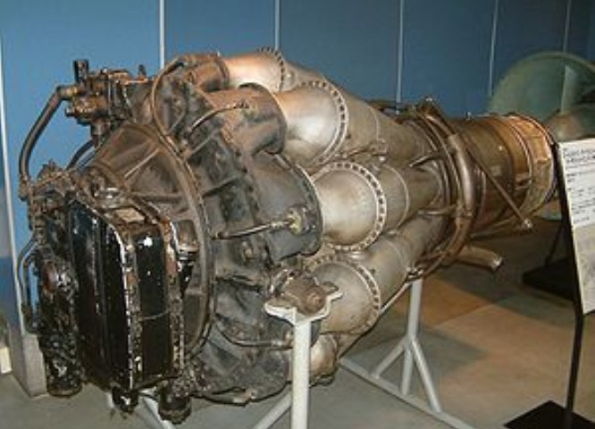
After a short period Lombard decided to dispense with Whittle’s “reverse flow” design, and instead lay out the engine in a “straight-through” flow with the hot gas exiting directly onto the turbine instead of being piped forward as in Whittle’s version. This layout made the engine somewhat longer and required a redesign of the nacelles on the Meteor, but also made the gas flow simpler and thereby improved reliability. While work at Barnoldswick continued on what was now known as the W.2B/23, Lombard’s new design became the W.2B/26 centrifugal compressor turbojet engine.

By 1941 it was obvious to all that the arrangement was not working; Whittle was constantly frustrated by what he was seeing as Rover’s inability to deliver production-quality parts for a test engine, and became increasingly vocal about his complaints. Likewise Rover was losing interest in the project after the delays and constant harassment from Power Jets in the critical testing process stage, where testing new designs and materials to breaking point is vital. Earlier, in 1940, Stanley Hooker of Rolls-Royce had met with Whittle, and later introduced him to Rolls’ CEO, Ernest Hives. Rolls had a fully developed supercharger division, directed by Hooker, which was naturally suited to jet engine work. Hives agreed to supply key parts to help the project along. Eventually Spencer Wilks of Rover met with Hives and Hooker, and decided to trade the jet factory at Barnoldswick for Rolls’ Meteor tank engine factory in Nottingham. A handshake sealed the deal, turning Rolls-Royce into the powerhouse it remains to this day. Subsequent Rolls-Royce jet engines would be designated in an “RB” series, standing for Rolls Barnoldswick, the /26 Derwent becoming the RB.26.

Problems were soon ironed out, and the original /23 design was ready for flight by late 1943. This gave the team some breathing room, so they redesigned the /26’s inlets for increased air flow, and thus thrust. Adding improved fuel and oil systems, the newly named Derwent Mk.I entered production, the second Rolls-Royce jet engine to enter production, with 2,000 lbf (8.9 kN) of thrust. Mk.II, III and IV’s followed, peaking at 2,400 lbf (10.7 kN) of thrust. The Derwent was the primary engine of all the early Meteors with the exception of the small number of Welland-equipped models which were quickly removed from service. The Mk.II was also modified with an extra turbine stage driving a gearbox and, eventually, a five-bladed propeller, forming the first production turboprop engine, the Rolls-Royce RB.50 Trent.

The project was to be of the same maximum diameter, in order that it might be installed in standard Meteor nacelles, but it was to develop 2,000 lb thrust. Drawings were started in April 1943 and by July the new unit was ready for test. In November of that year it passed its 100-hr type-test at the full 2,000 lb rating and in April the following year it went through its first flight tests in a Meteor, with a Service rating of 1,800 lb and a weight of 920 lb.

The Derwent II gave a thrust of 2,200 lb, and the III was a special unit to provide suction for boundary-layer removal; the Derwent IV was rated at 2,400 lb thrust. The Derwent 5 was an entirely new engine-still of 43in diameter, but developing twice the thrust of the original Derwent I. It was, in effect, a scaled-down version of the Nene, and its development was motivated by the promise shown by the Nene and the knowledge that the Meteor could utilize thrust greatly in excess of the original estimates.

The basic Derwent design was also used to produce a larger 5,000 lbf (22.2 kN) thrust engine known as the Rolls-Royce Nene. Development of the Nene continued in a scaled-down version specifically for use on the Meteor, and to avoid the stigma of the earlier design, this was named the Derwent Mk.V. Several Derwents and Nenes were sold to the Soviet Union by the then Labour government, causing a major political row, as it was the most powerful production-turbojet in the world at the time. The Soviets promptly reverse engineered the Derwent V and produced their own unlicensed version, the Klimov RD-500. The Nene was reverse-engineered to form the populsion unit for the famous MiG-15 jet fighter. The Derwent Mk.V was also used on the Canadian Avro Jetliner, but this was never put into production.

On 7 November 1945, a Meteor powered by the Derwent V set a world air speed record of 606 mph (975 km/h) TAS.

An unusual application of the Derwent V was to propel the former paddle steamer Lucy Ashton. The 1888 ship had her steam machinery removed and replaced by four Derwents in 1950–1951. The purpose of this was to conduct research on the friction and drag produced by a ship hull in real life conditions. Jets were preferable to marine propellers or paddles as these would have created a disturbance in the water, and the force exerted by them was harder to measure. The four engines could propel the Lucy Ashton at a speed in excess of 15 knots (28 km/h; 17 mph).

The Derwent 5 was superseded by the Derwent 8 and 9. The 8 incorporated two outlets to feed compressor-air through piping to heater muffs on the exhaust unit; tappings were taken from these muffs to heat the cabin and the guns and/or camera. The 9 used the same method of heating, but had in addition larger combustion chamber-inter-connectors and high-energy ignition to give more consistent relighting in flight as well as to increase the altitude at which relighting was possible.

Experimental Derwents included the RD.9, which had a 15 per cent increase in mass flow, and the RD.10-a scaled-up version utilizing the rotating parts of the Nene. The RD.11 was another scaled-up development.

The body of a typical Derwent is built up on the compressor rear casing which, though immensely strong, is very light and is considered by Rolls-Royce to be a fine example of their foundry technique. On the front face are the diffuser ring, the front casing and front air intake, and the wheelcase. To the rear the main structure comprises the rear air intake, the cooling-air casing and the centre and’rear bearing-housings, which successively lead to the nozzle-box assembly. This last takes the gas flow from the combustion chambers and distributes it to the annulus of stationary nozzle-guide vanes; it also carries the auxiliary coolingair ducts leading from the region of the turbine disc and rear bearing housing.

Centrally runs the main rotating assembly, and disposed round the engine, between the compressor casing outlet elbows and the nozzle-box, are the nine combustion chambers. So carefully balanced is the rotating assembly that as much as a minute and a half elapses before it comes to rest after the engine is shut down, At maximum static thrust the characteristic double-sided impeller deals with 62 lb of air per second, with an efficiency of 80 per cent and a compression ratio of 4 : 1. For this task it needs about 8,000 h.p., which is transmitted from the turbine through the coupling. The impeller is 24in in diameter and has 29 vanes on each side. Guide vanes convert axial to radial flow.

Variants:
Derwent I – first production version. Straight-thru development of the trombone style W.2 configuration, with compressor and turbine upflowed by 25% to give 2000lbf (8.9 kN) static thrust
Derwent II – thrust increased to 2,200 lbf (9.8 kN)
Derwent III – experimental variant providing vacuum for wing boundary layer control
Derwent IV – thrust increased to 2,400 lbf (10.7 kN)
Derwent 5 – scaled-down version of the Rolls-Royce Nene developing 3,500 lbf (15.6 kN) of thrust
Derwent 8 – developed version giving 3,600 lbf (16.0 kN) of thrust

Applications:
Avro 707
Avro Canada C102 Jetliner
Fairey Delta 1
Fokker S.14 Machtrainer
Gloster Meteor
Nord 1601
FMA I.Ae. 27 Pulqui I

Specifications:

Derwent I
Type: Centrifugal compressor turbojet
Length: 84 in (2,133.6 mm),
Diameter: 43 in (1,092.2 mm)
Dry weight: 975 lb (442.3 kg),
Compressor: 1-stage double-sided centrifugal compressor
Combustors: 10 x can combustion chambers
Turbine: Single-stage axial
Fuel type: Kerosene (R.D.E.F./F/KER)
Oil system: pressure feed, dry sump with scavenge, cooling and filtration, oil grade 150 S.U. secs (32 cs) (Intavia 7106) at 38 °C (100 °F)
Maximum thrust: 2,000 lbf (8.90 kN) at 16,000 rpm at sea level
Overall pressure ratio: 3.9:1
Turbine inlet temperature: 1,560 °F (849 °C)
Specific fuel consumption: 1.17 lb/lbf/hr (119.25 kg/kN/hr)
Thrust-to-weight ratio: 2.04 lbf/lb (0.0199 kN/kg)
Military, static: 2,000 lbf (8.90 kN) at 16,600 rpm at sea level
Cruising, static: 1,550 lbf (6.89 kN) at 15,400 rpm at sea level
Idling, static: 120 lbf (0.53 kN) at 5,500 rpm at sea level

Derwent V
Type: Centrifugal compressor turbojet
Length: 88.5 in (2,247.9 mm)
Diameter: 43 in (1,092.2 mm)
Dry weight: 1,250 lb (567.0 kg)
Compressor: 1-stage double-sided centrifugal compressor
Combustors: 10 x can combustion chambers
Turbine: Single-stage axial
Fuel type: Kerosene (R.D.E.F./F/KER)
Oil system: pressure feed, dry sump with scavenge, cooling and filtration, oil grade 150 S.U. secs (32 cs) (Intavia 7106) at 38 °C (100 °F)
Maximum thrust: 4,000 lbf (17.79 kN) at 15,000 rpm at sea level
Overall pressure ratio: 3.9:1
Turbine inlet temperature: 1,560 °F (849 °C)
Specific fuel consumption: 1.02 1.28 lb/lbf/hr (103.97 kg/kN/hr)
Thrust-to-weight ratio: 3.226 1.724 lbf/lb (0.0316 kN/kg)
Military, static: 3,500 lbf (15.57 kN) at 14,600 rpm at sea level
Cruising, static: 3,000 lbf (13.34 kN) at 14,000 rpm at sea level
Idling, static: 120 lbf (0.53 kN) at 5,500 rpm at sea level

Derwent 8
Maximum thrust: 3,600 lb at 14,700 r.p.m
Specific fuel consumption: 1.01 lb/hr/Ib.

Rolls-Royce Dart

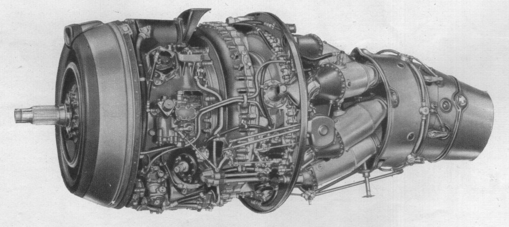
This turboprop achieved renown as the power unit of the Vickers Viscount, it has also been flown on a limited scale in the Avro Athena and Boulton Paul Balliol advanced trainers.

The Dart is characterized by a two-stage centrifugal compressor, handling about 20 lb of air per second, and a two-stage turbine. Steel guide vanes direct the air between the 19 rotor blades, from which it is impelled at high speed. After passing through a diffuser the flow is directed through curved passages, formed by the compressor casings and inter-stage guide vanes, into the second rotor.

The two stages of the turbine are locked together on a common shaft and the blades of the high and low pressure, stages have “fir tree” roots. Both discs are cooled on their front and rear faces, and a steel-strip seal prevents gas leakage between the stages. There are seven combustion chambers.

Dart final checks at Derby

Under tropical conditions lost take-off power is restored by water/methanol injection.

The Dart RDa.6 was in production for Viscounts, and has a new reduction gear and other refinements, making possible a maximum rating of 1,500 h.p. The RDa.5 was completely new, and designed for even greater powers. It is scheduled to power the Viscount 800 Series.

Dart 505
Diameter, 37.9in
Length, 95.1in
Dry weight, 1,030 lb
Max. power, 1,400 s.h.p. plus 365 lb thrust
Equivalent shaft horsepower, 1,515 at 14,500 r.p.m
Specific fuel consumption, 0.83 lb/hr/e.s.h.p.

Rolls-Royce Crécy

Sir Henry Tizard, Chairman of the Aeronautical Research Committee (ARC), was a proponent of a high-powered “sprint” engine for fighter aircraft and had foreseen the need for such a powerplant as early as 1935 with the threat of German air power looming. It has been suggested that Tizard influenced his personal friend Harry Ricardo to develop what eventually became known as the Rolls-Royce Crecy. The idea was officially discussed for the first time at an engine sub-committee meeting in December 1935.

“The Chairman remarked that if it was the desire of the Air Ministry to develop a type of sprint engine for home defence….there was the question as to how far fuel consumption could be disregarded. Mr Ricardo had raised this point in a recent conversation by enquiring whether a high fuel consumption might not be permissible under certain circumstances, for if so, an investigation of the possibilities of the two-stroke petrol engine appeared to be attractive.”
—Henry Tizard, The Rolls-Royce Crecy

Previous experience gained between 1927 and 1930 using two converted Rolls-Royce Kestrel engines through an Air Ministry contract had proven the worth of further research into a two-stroke sleeve-valved design. Both these engines had initially been converted to diesel sleeve-valved operation with a lower power output than the original design being noted along with increased mechanical failures, although one converted Kestrel was subsequently used successfully by Captain George Eyston in a land-speed record car named Speed of the Wind. The second engine was further converted to petrol injection which then gave a marked power increase over the standard Kestrel.

Single-cylinder development began in 1937 under project engineer Harry Wood using a test unit designed by Ricardo. Although originally conceived as a compression ignition engine, by the time Rolls-Royce started serious development, in conjunction with the Ricardo company, the decision had been taken by the Air Ministry to revert to a more conventional spark-ignition layout, although still retaining fuel injection.

The first complete V12 engine was built in 1941, designed by a team led by Harry Wood with Eddie Gass as the Chief Designer. Bore was 5.1 in (129.5 mm), stroke 6.5 in (165.1 mm), compression ratio 7:1 and weight 1,900 lb (862 kg). The firing angle was 30 degrees BTDC, and 15 lbf/sq.in (100 kPa) supercharger boost was typical. First run on 11 April 1941, in bench-testing it produced 1,400 horsepower (1,000 kW); however, there were problems with vibration and the cooling of the pistons and sleeves. The thrust produced by the exceptionally loud two-stroke exhaust was estimated as being equivalent to a 30% increase in power at the propeller on top of the rated output of the engine. The power of the engine was interesting in its own right, but the additional exhaust thrust at high- speed and altitude could have made it a useful stop gap between engines such as the Rolls-Royce Merlin and anticipated jet engines. Serial numbers were even, Rolls-Royce practice being to have even numbers for clockwise rotating engines when viewed from the front.

The reciprocating sleeve valves were open-ended rather than sealing in a junk head – the open end uncovered the exhaust ports high in the cylinder wall at the bottom of the sleeves’ stroke, leaving the ports cut into the sleeve to handle the incoming charge only. They had a stroke of 30% of the piston travel at 1.950 in (49.5 mm) and operated 15 degrees in advance of the crankshaft. The Crecy sleeve valves were of similar construction but differed in their operation compared to the rotary sleeve valve design that was pioneered by Roy Fedden, and used successfully for the first time in an aircraft engine, the Bristol Perseus, in 1932.

Unlike most two-stroke engines, supercharging was used rather than crankcase compression to force the charge into the cylinder – this also allowed for a conventional oil lubrication system instead of the total-loss type found in many two-stroke engines. Stratified charge was used where the fuel was injected into a bulb-like extension of the combustion chamber where the twin spark plugs ignited the rich mixture. Operable air-fuel ratios of from 15 to 23:1 were available to govern the power produced between maximum and 60%. The rich mixture maintained near the spark plugs reduced detonation allowing higher compression ratios or supercharger boost. Supercharger throttling was used as well to achieve idling. The supercharger throttles were novel vortex types, varying the effective angle of attack of the impeller blades from 60 to 30 degrees. This reduced the power required to drive the supercharger when throttled, and hence fuel consumption at cruising power.

Later testing involved the use of an exhaust turbine which was a half-scale version of that used in the Whittle W.1 turbojet, the first British jet engine to fly. Unlike a conventional turbocharger the turbine was coupled to the engine’s accessory driveshaft and acted as a power recovery device. It was thought that using the turbine would lower fuel consumption allowing the engine to be used in larger transport aircraft. This was confirmed during testing however failures due to severe overheating and drive shaft fractures were experienced.

Test summary
The following summarises the test running programme, hours run, and highlights some of the failures experienced.

Crecy 2

11 April 1941
First run. One-piece cylinder block/head. Testing stopped due to piston failure.
Hours run: 69

October 1942 – December 1942
Three rebuilds during this period, testing stopped after 35 hours due to piston seizure.
Hours run: 67

February 1943 – July 1943
Converted to Mk II configuration (separate cylinder heads), three rebuilds during this period. Air Ministry acceptance test passed.
Hours run: 38

March 1944 – July 1944
Five rebuilds during this period. Equal length injector pipes fitted, modified supercharger drive. Two failures, sleeve valve seizure and supercharger drive failure.
Hours run: 82

August 1944 – November 1944
Successful type test passed (112 hours). Post run inspection revealed cracked big-end bearings, pistons, reduction gear housing and sleeve valve eccentric drive bearing.
Hours run: 150

March 1945 – April 1945
Attempted endurance test, piston failure after 27 hours. Two rebuilds during this period.
Hours run: 49

(Total hours: 461)

Crecy 4

November 1941
No report available.
Hours run: 55

July 1942 – August 1942
Three rebuilds, successful 50-hour test, second 50-hour test abandoned after cylinder block failure due to cracking.
Hours run: 80

September 1942 – October 1942
Two rebuilds. Completed 25-hour test successfully, second test halted after four hours running due to sleeve valve failure.
Hours run: 55

(Total hours: 293)

Crecy 6

July 1943 – February 1944
First engine built as Mk II. Eight rebuilds during this period, failures included supercharger drive failure and sleeve valve eccentric drive bolt fracture.
Hours run: 126

May 1944 – September 1944
Four rebuilds. Supercharger flexible drive failure and sleeve valve seizure.
Hours run: 93

November 1944 – February 1945
Three rebuilds, main bearing failure, piston failure.
Hours run: 128

June 1945 – August 1945
One rebuild, endurance test halted after 95 hours due to sleeve valve drive failure, 40 hours run with a propeller fitted.
Hours run: 132

(Total hours: 481)

Crecy 8

September 1943 – March 1944
Eight rebuilds, endurance test successfully completed.
Hours run: 207

April 1944
Supercharger drive failure.
Hours run: 73

June 1944 – September 1944
Five rebuilds, no failures reported.
Hours run: 32

October 1944 – December 1945
Two rebuilds, piston failure, engine fitted with exhaust turbine.
Hours run: 22

(Total hours: 336)

Crecy 10

August 1944 – February 1945
Six rebuilds, melted inlet manifold after seven hours, sleeve valve seizure after a further four hours. Two injector pump failures.
Hours run: 53

March 1945 – June 1945
One rebuild, piston failure.
Hours run: 30

July 1945 – September 1945
Two rebuilds, exhaust turbine fitted, some running without supercharger. Sleeve valve and supercharger drive failure.
Hours run: 82

(Total hours: 166)

Crecy 12

January 1945 – October 1945
Four rebuilds, exhaust turbine fitted. Turbine failure, piston failure and sleeve valve drive failure.
(Total hours: 67)

The progress of jet engine development overtook that of the Crecy and replaced the need for this engine. As a result work on the project ceased in December 1945 at which point only six complete examples had been built, however an additional eight V-twins were built during the project. Crecy s/n 10 achieved 1,798 horsepower (1,341 kW) on 21 December 1944 which after adjustment for the inclusion of an exhaust turbine would have equated to 2,500 horsepower (1,900 kW). Subsequent single-cylinder tests achieved the equivalent of 5,000 brake horsepower (3,700 kW) for the complete engine. By June 1945 a total of 1,060 hours had been run on the V12 engines with a further 8,600 hours of testing on the V-twins. The fate of the six Crecy engines remains unknown.

If the Crecy had flown it would have done so using a Hawker Henley, L3385 which was delivered to Hucknall for conversion on 28 March 1943. This aircraft remained at Hucknall until 11 September 1945 when it was scrapped without ever having the engine fitted.

Two years prior to the Hawker Henley’s arrival (Summer 1941) a Supermarine Spitfire Mk II, P7674 had been delivered to Hucknall and was fitted with a Crecy mock-up to enable cowling drawings and system details to be designed. It had also been agreed that the first production Spitfire Mk III would be delivered to Hucknall in early 1942 minus its Merlin engine for fitment of an airworthy Crecy; this delivery did not occur however. A Royal Aircraft Establishment report (No. E.3932) of March 1942 estimated the performance of the Spitfire fitted with a Crecy engine and also compared this to a Griffon 61-powered variant of the type. The report stated that the Crecy’s maximum power output would be too much for the Spitfire airframe but that a derated version would have considerable performance gains over the Griffon-powered fighter.

Crecy
Type: 12-cylinder supercharged liquid-cooled 2-stroke aircraft piston engine
Bore: 5.1 in (129.5 mm)
Stroke: 6.5 in (165.1 mm)
Displacement: 1,536 cu.in (26 lt)
Dry weight: 1,900 lb (862 kg)
Valvetrain: Crankshaft-driven reciprocating sleeve valves
Supercharger: Gear-driven centrifugal type supercharger with variable angle of attack of the impeller blades providing up to 24 psi (165 kPa) of boost.
Turbocharger: Three engines fitted with exhaust turbine (50% scale version of Whittle W.1 turbine)
Fuel system: Direct fuel injection, 2 x CAV 6-cylinder pumps
Fuel type: 100 Octane petrol
Oil system: Gear pump
Cooling system: Liquid-cooled
Reduction gear: 0.451:1 (Left-hand tractor)
Power output: 2,729 hp (2,035 kW)
Specific power: 1.77 hp/cu.in (78.2 kW/L)
Compression ratio: 7:1
Fuel consumption: 85.4 gal/hr (388.2 L/hr) at 2,500 rpm
Specific fuel consumption: 0.55 pints/hp/hr at 1,800 rpm (with exhaust turbine)
Power-to-weight ratio: 1.43 hp/lb (2.36 kW/kg)

Rolls-Royce RB.80 Conway

Rolls-Royce Conway RCo.17 Mk201

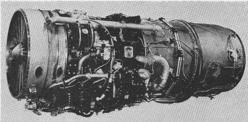
In early jet engines the exhaust was much faster and hotter than it had to be (contrary to the ideal Froude efficiency) for efficient thrust; capturing some of that energy would improve the fuel economy of the engine. The turboprop is an obvious example, which uses a series of additional turbine stages to capture this energy to power a propeller. However there is a tradeoff in propeller efficiency compared to forward speed, so while the turboprops are efficient engines, they are only efficient at speeds of up to 500 mph (800 km/h; 430 kn). This meant there was a sweet spot between the high efficiencies of the turboprop at low speeds and the jet at high speeds that was not being directly addressed. This spot, between about 450 mph (720 km/h; 390 kn) and 700 mph (1,100 km/h; 610 kn), was precisely where the vast majority of commercial jet aircraft spent most of their time.

The basic concept of bypass had been studied from the earliest days of jet engine design. Alan Arnold Griffith had proposed a number of different bypass engine designs as early as the 1930s while he and Hayne Constant were trying to get their axial-flow jet engines working at the Royal Aircraft Establishment. Frank Whittle’s Power Jets also studied a number of bypass configurations. However, the need to get jet engines into service during the war meant this work had to be put aside in favour of simpler designs with shorter introduction times. The ending of the war changed priorities dramatically, and by 1946 Rolls-Royce agreed that existing engines like the Rolls-Royce Avon were advanced enough that it was time to start work on new concepts like bypass.

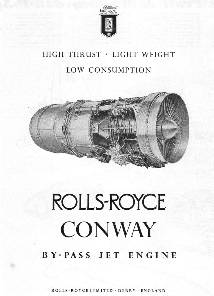
Griffith suggested building a purely experimental design using parts of the Avon and another experimental jet engine, the AJ.25 Tweed. In April 1947 a 5,000-pound-force (22,000 N) design was proposed, but over the next few months it was modified to evolve into a larger 9,250-pound-force (41,100 N) design in response to a need for a new engine to power the Mk.2 low-level version of the Vickers Valiant bomber. A go-ahead to start construction of this larger design was given in October, under the RB.80 name. The Rolls-Royce RB.80 Conway was the first by-pass engine (or turbofan) in the world to enter service. The name “Conway” is an Anglo-Saxon permutation of River Conwy, in Wales, in keeping with Rolls’ use of river names for jet engines.

During development it was decided to further improve the basic design by adding another feature then becoming common, a “two spool” compressor arrangement. Earlier engines generally consisted of a series of compressor stages connected via a shaft to one or more turbine stages, with the burners between them arranged around the shaft. Although this arrangement is mechanically simple, it has the disadvantage of lowering the efficiency of the compressor. Compressor stages run at their maximum efficiency when spinning at a specific speed for any given input air pressure – in a perfect compressor each stage would run at a separate speed. The multi-spool design, first used on the Bristol Olympus turbojet, is a compromise, the compressor is separated into “spools” designed to operate closer to most efficient speed, driven by separate turbines via concentric shafts. Two and three-spool designs are common, beyond that the mechanical complexity is too great.

The new version had a four stage low-pressure compressor driven by a two-stage turbine, and an eight stage high-pressure compressor driven by another two-stage turbine. Now known by the Ministry of Supply designation as the RCo.2, design work was completed in January 1950 and the first example ran for the first time in July 1952 at 10,000 pounds-force (44,000 N) thrust. By this time the low-level Valiant Pathfinder had been abandoned, and so the first example was also destined to be the last. Nevertheless it proved the basic concept sound, and “ran perfectly for the whole of its 133 hours life.”

Conway RC012

The work on the RCo.2 was soon put to good use. In October 1952 the Royal Air Force awarded a contract for the Vickers V-1000, a large jet-powered strategic transport that was intended to allow the V bomber force to be supported in the field through air supply only. Vickers also planned on developing a passenger version of the same basic design as the VC-7. The V-1000 design looked like an enlarged de Havilland Comet, but from the Valiant it took the wing layout and added a compound sweep (a passing vogue in UK design). It also featured the Comet’s wing-embedded engines, demanding an engine with a small cross-section, which limited the amount of bypass the engine could use. It nevertheless required higher power to support a 230,000 pounds (100,000 kg) gross weight, so Rolls responded with the larger RCo.5.

The new engine was similar to the RCo.2 in most ways, differing in details. The low-pressure compressor now had six stages, and the high-pressure nine, driven by two and one stage turbines respectively. The first RCo.5 ran in July 1953, and passed an official type rating in August 1955 at 13,000 pounds-force (58,000 N). Construction of the prototype V-1000 was well underway at Vickers Armstrongs’ Wisley works in the summer of 1955 when the entire project was cancelled. Having second thoughts about the concept of basing the V-bombers away from the UK, the need for the V-1000 became questionable and it became an easy decision to drop the project.

The Conway was saved once again when it was selected to power the Handley Page Victor B.2 variant, replacing the Armstrong Siddeley Sapphire of earlier models. For this role Rolls designed an even larger model, the RCo.8 of 14,500 pounds-force (64,000 N), which ran for the first time in January 1956. However the RCo.8 was skipped over after receiving a request from Trans-Canada Airlines (TCA) to explore a Conway powered Boeing 707 or Douglas DC-8, having interested both companies in the idea. Rolls responded by designing an even larger model of the Conway, the 16,500 pounds-force (73,000 N) RCo.10, and offering the similar military-rated RCo.11 for the Victor. The new engine differed from the RCo.8 in having a new “zeroth stage” at the front of the low-pressure compressor, further increasing cold airflow around the engine. The RCo.10 first flew in an Avro Vulcan on 9 August 1957, followed by the RCo.11 in the Victor on 20 February 1959.

1956

Boeing had calculated that the Conway, even though it had limited bypass in keeping with its original in-wing mounting, would increase the range of the 707-420 by 8% compared to the otherwise identical 707-320 powered by the non-bypass Pratt & Whitney JT4A (J75). In May 1956 TCA ordered Conway-powered DC-8s, followed by additional orders from Alitalia and Canadian Pacific Air Lines, while the Conway powered 707 was ordered by BOAC, Lufthansa, Varig and Air India. RCo.10’s development was so smooth that after delivering a small number for testing, further deliveries switched to the 17,150-pound-force (76,300 N) RCo.12, which was designed, built and tested before the airframes had finished their testing. These models also featured a distinctive scalloped silencer, and a thrust reverser that could provide up to 50% reverse thrust.

The RCo.12 Conway was an axial-flow turbofan with a low bypass ratio of about 25%. It had a seven-stage low-pressure compressor, the first six stages made of aluminium and the last of titanium. Behind this was the nine-stage high-pressure compressor, the first seven stages of titanium and the last two of steel. The bypass housing duct was also made of titanium. The combustion area consisted of ten cannular flame cans. The high-pressure compressor was driven by a single-stage turbine using hollow air-cooled blades, which was followed by the two-stage turbine powering the low-pressure compressor. Accessories were arranged around the front of the engine, leading to a minimum of increased diameter.
The engine produced 17,150 pounds-force (76,300 N) for takeoff, weighed 4,500 pounds (2,000 kg) and had a specific fuel consumption of 0.712 at take-off thrust and 0.87 for cruise.

Although successful in this role, only sixty-nine 707’s and DC-8s were built with the Conway, due largely to the delivery of the first US-built bypass engines, particularly the Pratt & Whitney JT3D. Nevertheless the Conway was successful on these designs, and was the first commercial aero engine to be awarded clearance to operate for periods up to 10,000 hours between major overhaul.

Rolls continued working on the Conway, delivering the RCo.15. This was similar to the earlier RCo.12, but had a larger zeroth-stage along with a larger engine housing to fit it. This improved cruise fuel consumption by 3% while at the same time increasing take-off thrust to 18,500 pounds-force (82,000 N). The designs were otherwise similar, and RCo.12’s could be re-built into RCo.15’s during overhauls.

The final development of the Conway series was the RCo.42, designed specifically for the Vickers VC10. As the need for wing-embedded engines was long abandoned by this point, Rolls dramatically increased the zeroth-stage diameter to increase the bypass from about 25% to 60%, and further increasing thrust to 20,250 pounds-force (90,100 N). First run in March 1961, it would be the most successful of all the Conways, powering all of the VC10 fleet, later models with the RCo.43.

By 1968 a Hyfil carbon-fibre fan assembly was in service on Conways of the VC10s operated by BOAC.

Variants:
RCo.2
RCo.5
RCo.8
RCo.10
RCo.11
RCo.12
RCo.17
RCo.42
RCo.42/1
RCo.43

Applications:
Boeing 707-420
Douglas DC-8-40
Handley Page Victor
Vickers VC10

Specifications:
Conway
Type: Turbofan
Length: 134.21 in (3,409 mm)
Diameter: 37.6 in (960 mm)
Dry weight: 4,500 lb (2,000 kg)
Compressor: axial flow; 7-stage LP, 9-stage HP
Combustors: cannular
Turbine: axial flow; 1-stage HP, 2-stage LP
Maximum thrust: 17,150 lb (76.3 kN)
Bypass ratio: 0.25
Specific fuel consumption: 0.87