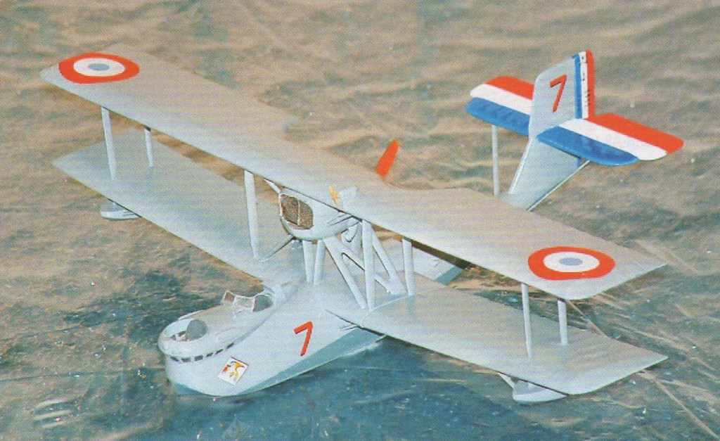
For shipborne observation/patrol, CAMS’ bay-windowed 37A first flew in 1926. About 150 were produced in the inter-war years. With its Lorraine 450hp broad arrow V12 and coarse pitch and small diameter pusher propeller it lasted longer than most with one example being operated by the Free-French from Tahiti. It could be operated from land strips when a wheeled main gear was attached, but was not capable of amphibious use since it could neither take off nor land on water in this configuration.
Chantiers Aero-Maritimes de la Seine founded 1921, specializing in production of marine aircraft; technical director and chief designer from 1927 was Maurice Hurel. Best-known products were flying-boats; CAMS 33, built 1923-1926 originally for the Schneider Trophy race; CAMS 37 for shipborne observation/patrol; and the CAMS 51, 53 and 55 family, of which the CAMS 55 was a patrol bomber. Company acquired in 1933 by Societe des Avions et Moteurs Henry Potez. Factories at Sartrouville and Vitrolles nationalized in 1937. Les Mureaux, CAMS, and part of Breguet formed SNCAN in 1938.
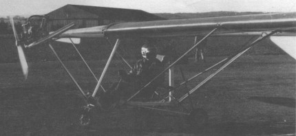
Single seat single engined high wing mono¬plane with conventional three axis control. Wing has swept back leading edge, unswept trailing edge and tapering chord; cruciforin tail. Pitch control by elevator on tail; yaw control by fully flying rudder with additional fin; roll control by wing warping; control inputs through stick for pitch/roll and pedals for yaw. Wing braced from below by struts; 100% double surface. Undercarriage has three wheels in tricycle formation; coil spring suspension on nose¬wheel and disc spring suspension on main wheels. Push right go right nosewheel steer¬ing connected to yaw control. Brake on nosewheel. Aluminium tube framework, without pod. Engine mounted at wing height driving tractor propeller. Although the Ladybird is the first microlight to carry his name Mike Campbell Jones is no stranger to the micro¬light industry, having worked at one time or another for Hiway and Huntair in Britain, and Fulmar and the EMC 2 company in Belgium. The Ladybird does not set out to be a high performance aircraft, at least not in terms of climb rate and speed. Instead, Mike has tried to create a light, simple machine with a good glide ratio and pleasant handling. The pro¬totype Ladybird was shown at the Long Marston fly in during August ’82 and was generally well received; however it was obviously in need of refinement and since then push rods and bell cranks have re¬placed control cables, the rudder has been down sized to eliminate over sensitivity and a differential movement has been built into the wing warping mechanism, to give the ‘up’ wing more movement than the ‘down’. The Ladybird’s most unusual feature is its wing warping mechanism, however, this mechanism is not just for roll control; a separate lever allows the pilot to twist both wings equally to adjust the speed range, thus permitting the pilot to select a slower stall speed in preparation for a tricky landing. In 1983, the aircraft was powered by a Hiro engine, but Mike was not satisfied with its reliability and was consider¬ing substituting the 330 Robin for production aircraft.
Engine: Hiro Delta Mk I, 22 hp at 7500 rpm. Propeller diameter: 54 inch, 1.37m. Gearbox reduction, ratio 3.0/1. Max static thrust 130 lb, 59 kg. Power per unit area 0.16hp/sq.ft, 1.7hp/sq.m Fuel capacity 4.8 US gal, 4.0 Imp gal, 18.2 litre. Empty weight 250 lb, 113kg. Max take off weight 475 lb, 215kg. Payload 225 lb, 102 kg. Max wing loading 3.49 lb/sq.ft, 17.1 kg/sq.m. Max power loading 21.6 1b/hp, 9.8kg/hp. Load factors +6.0, 3.0 design Length overall 18.0 ft, 5.50 m. Height overall 7.4ft, 2.26m. Wing span 36.1ft, 11.00m. Chord at root 4.6ft, 1.40m. Chord at tip 3.0ft, 0.90m. Dihedral: 2deg. Sweepback: 7.5deg Tailplane span 6.3 ft, 1.91 m. Fin height 2.0 ft, 0.61 m. Total wing area 136 sq.ft, 12.6 sq.m. Fin area 1.5sq.ft, 0.14 sq.m. Rudder area 9.5sq.ft, 0.88 sq.m. Tailplane area 10.0 sq.ft, 0.93 sq.m. Total elevator area 22.0 sq.ft, 2.04 sq.m. Wing aspect ratio 9.64. Wheel track 5.0 ft, 1.52 m. Wheelbase 5.5 ft, 1.68 m. Nosewheel diameter overall 13 inch, 33 cm. Main wheels diameter overall 13 inch, 33 cm. Floats, dimensions length 12 ft, 3.7 m. Max level speed 55 mph, 88 kph. Never exceed speed 65 mph, 105 kph. Max cruising speed 50 mph, 80 kph. Economic cruising speed 45mph, 72kph. Stalling speed 25 28mph, 40 45kph. Best glide ratio with power off 13/1 at 45 mph, 72 kph. Take off distance 150 ft, 45 m. Land¬ing distance 100ft, 30m. Service ceiling 3000ft, 910m. Range at average cruising speed 100 mile, 161 km.
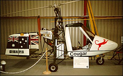
The Campbell Aircraft Company was founded in the late 1950’s to develop and build autogyros and in 1969 began production of the single seat Cricket autogyro. This was later followed by a two-seat project and the construction of a single seat prototype was carried out by Western Airways at Weston-super-Mare Airport in early 1973. Powered by a single Rolls Royce Continental O-240-A 4-cylinder ‘flat-four’ piston engine it first flew in April 1973.
Cricket autogyros were still being manufactured in 2007, and Peter Lovegrove who was the original designer of the Cougar and Cricket was still involved.
Based at Hungerford, Berkshire, Campbell acquired U.K. rights for manufacture and sale of Bensen range of U.S. Gyro-Gliders and Gyro-Copters in 1959. First license-built example flew August 1960. Bensen range reduced to two models in 1969, when Campbell designed own two-seat light autogyro, the Curlew. Development abandoned in favor of the single-seat Cricket in July 1969; 47 were built by April 1972. Cougar single/two-seat prototype flew March 1973, but was not produced.
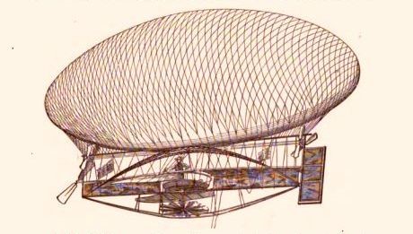
Powered by an Edison electric motor, its 18,000 cu. ft. envelope supplied by Carl E. Meyers, and built a cost of $2500 by the Novelty Air Ship Company of Brooklyn, N.Y., for Professor Peter C. Campbell; the first flight of which was made December 8, 1888 from Coney Island to Sheepshead Bay, piloted by Carlotta the aeronaut – the wife of Carl Meyers. At this time the motive of power is reported to have been bicycle pedals and multiplying gears. The Campbell Air Ship was lost at sea July 16, 1889 while being flown by Professor E. D. Hogan, a Canadian professional aerobat/parachutist, during an exhibition flight originating from the Nassau Gas Works. Intending to make a trip around New York, then to pass over to New Jersey and into the country, five minutes into the flight the 8 foot diameter lower propeller, with which Hogan was to raise and lower the Air Ship gave way and fell to the ground. To make matters worse, it was observed that the steering propellers did not seem to work as no revolutions were discernible, leaving Hogan at the complete mercy of the wind.
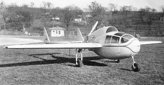
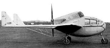
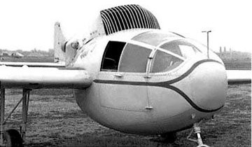
Designed and built in 1935 by Hayden Campbell in St. Joseph, Missouri, the Campbell F was made of all-magnesium construction and was powered by an 85 hp Ford V-8 automotive engine.The F model was equipped with a tricycle landing gear with steerable nosewheel.
Nicknamed ‘The Flying Easter Egg’, the aircraft was damaged in a demonstration flight and never repaired.
The goal of this side by side two-seater design was a cheap plane for tourism.
This aircraft was seen in a dismantled state in a barn south of Buffalo New York. Prior to that, it had been stored at the Hamburg, NY airfield on North Creek Road.
Engine: 85 hp Ford V-8 Wingspan: 36 ft Length: 19 ft 4in Max speed: 190 km/h Seats: 2 side to side