Chamberlin, Clarence Duncan

Born in Ohio, 1893. Died October 30, 1976.

Clarence Duncan Chamberlin, born in Ohio in 1893, first began flying while working at an aerial sign-towing company, then won his wings in 1918 after enlisting in the Aviation Section of the Signal Corps. After a tour of barnstorming he became a dealer in surplus aircraft sales, as well as a company pilot for Wright Corp.

When 1927 a $25,000 prize was offered in to the first pilot to cross the Atlantic in solo flight, Chamberlin was eager to try. That spring Charles Levine’s powerful Wright-Bellanca WB-1 Columbia proved it could endure the time barrier of an ocean flight when Chamberlin and Bert Acosta remained aloft for 51 hours over Roosevelt Field. Unfortunately, Levine was still puttering with the plane and arguing with his pilot and Giuseppe Bellanca when Charles Lindbergh landed in Paris on May 12.

However, on June 4 he and Levine flew non-stop to Germany, and his trip of some 43 hours and 3,905 miles later—which bettered Lindbergh’s distance record—landed on a small field near Eisleben. There they refueled with 20 gallons of fuel brought by a local farmer, and using a quart-size coffee pot to fill the tank, then headed for Berlin, but got lost and landed east of the city at Kottbus, where they received a small but tumultuous welcome. They did finally land at Tempelhof Airport the next afternoon to a crowd of more than 100,000 cheering Berliners.

He designed his own line of Crescent monoplanes, and flew one in the 1929 Air Races, then acquired a diesel-powered Lockheed Vega, in which he set a world altitude record of over 19,000 feet in 1932. He next formed Chamberlin Airline between New York and Boston, but when it seemed doomed for failure, he used its four Curtiss Condors for a barnstorming group during the next five years, plus having his own flight school and aircraft dealerships. When war clouds threaten in Europe, he opened a series of aviation trades schools vital for the war effort. After the war, he served briefly as sales manager for Bellanca Aircraft Corp for a time.

In 1939 he acquired the Rover rights from Jean Roché while in Jersey City NJ.
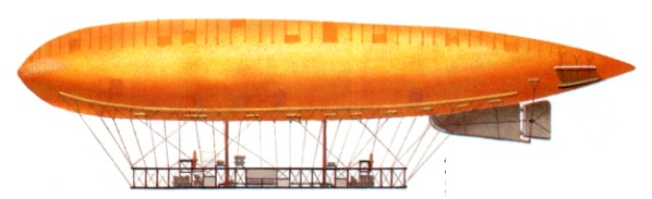
Chalais-Meudon Fleurus / CBV

When war broke out in 1914, French airship equipment was entirely of the non-rigid pattern, and it was one of these that became the first Allied airship to carry out an air raid. This was the Fleurus, which had been built (like all French army craft of the lighter-than-air type) in the workshops at Chalais¬Meudon two years earlier, being re¬garded as a smaller sister ship to L’Ad¬jutant Vincenot (C.B.IV).
The Fleurus (or C.B.V. as it was officially known), had for the period a good aerodynamically efficient shape as it had been de¬signed as a result of wind tunnel tests conducted at the Eiffel laboratory. While these results were applied to the contours of the envelope, Clement¬Bayard was responsible for the design of the motor and the gondola, hence the initials of the alternative designa¬tion.
During the last year of peace, great use was made of the vessel, which par¬ticipated in the army manoeuvres of that summer. It also left its base at Pau on 23 September at the beginning of a flight to Saint-Cyr, a journey which it completed in 16 hours, averaging a speed of 54 km/h (33.7 mph), rather less than its maximum, for the distance of 680 km (423 miles) at an altitude nev¬er more than 1000 m (3,281 ft).
When making its historic raid from Verdun, the F]eurus was officially an army airship, there being no equiva¬lent naval air arm; but with effect from 1 January 1917 this was rectified and the army vessels were handed over to establish the new branch of the navy. Of the six non-rigids involved, four were at once deployed for sea patrol in much the same manner as the British ‘North Sea’ and similar types, but by now the C.B.V was five years old and obsolescent, so that with another airship it was relegated to training duties. The base for this work was far from the area where the newer airships operated — North Africa’s Mediterranean coast — being instead no further afield than Rochefort. It was here the Fleurus ended its days, destroyed in a fire as a result of an air raid in June 1918.
National insignia had not been adopted at the time of the first flight to be made by Fleurus, but when it was introduced this vessel was one of the earliest in France to be thus marked.

Chalais-Meudon Fleurus I
Engines: two 59. 7-kW (80-hp Clement-Bayard four-cylinder water-cooled piston
Diameter 12 40 m (40ft 8.2 in)
Length 77.0m (252 ft 7.5in)
Contained volume : 229580 cu.ft / 6500 cu.m
Max. speed : 32 kts / 59 km/h
Service ceiling 1005 m (3,281 ft)
Range 680 km (423 miles)
Useful lift 5200 kg (11.464 lb).

Chaika L-4 / L-6 / L-44

L-44

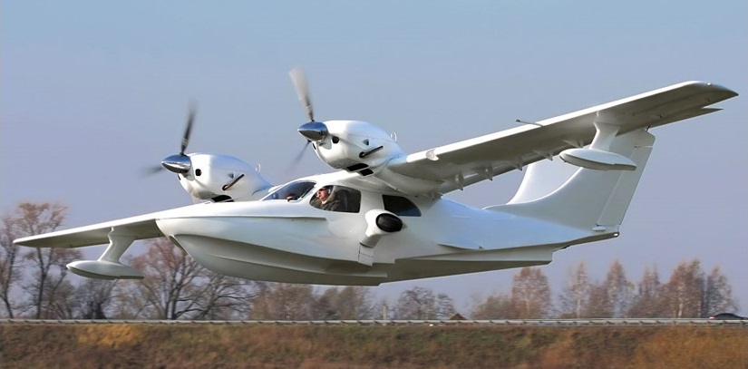
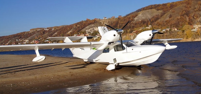
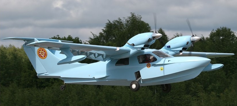
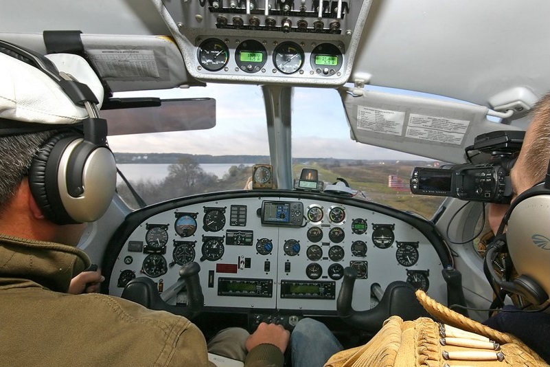
Several companies and groups have developed a series of designs which began at an offshoot of the Trod Kuznetsov aircraft engine plant in Samara. Beginning with the L-3, they differ in size and engine type but all are twin engine amphibians with a characteristic V tail. The L-4 is a direct development of the L-6M, promoted by AeroVolga. Its design began in August 2004.

L-44

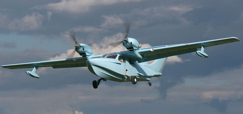
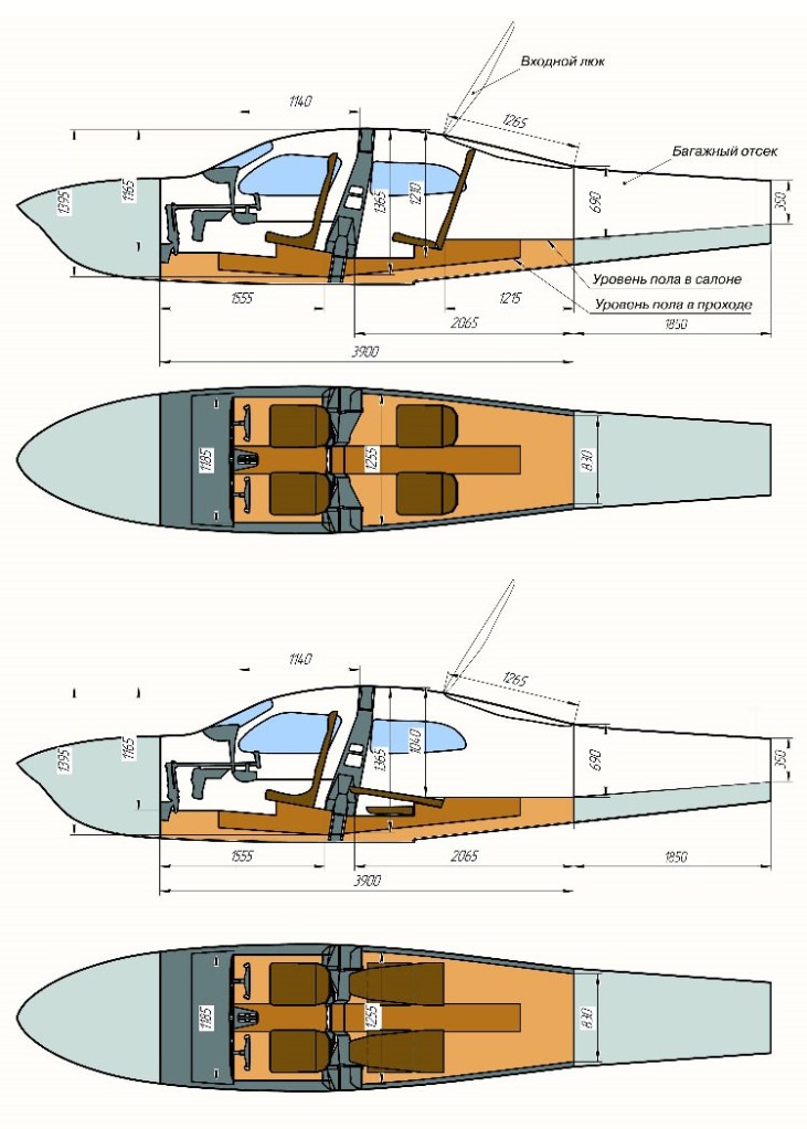
All L-4 variants have the same layout and all are largely built of composite materials. They are high-wing monoplanes with twin engines mounted close to the fuselage, on top of the wing. The wings have straight taper on both edges and almost square tips. The L-4 has a pair of flaps on each wing. Its hull has two steps and there are small winglets at waterlevel just aft of the trailing edge. The cabin extends from below the leading edge rearwards to the winglets. Fixed floats under the wings stabilize the L-4 on water; it is operable with waves to 400 mm (15 in) high.

L-44

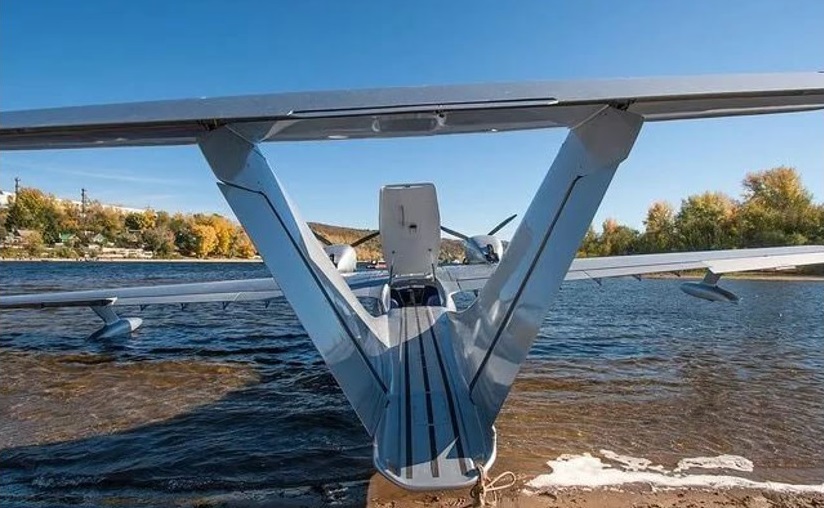
The most unusual feature of the L-4 is the empennage arrangement: it has twin fins, mounted on the fuselage and extended forward with long, curved dorsal fillets, separated at the base by the full fuselage width and leaning slightly outwards. The fins carry conventional rudders and the single tailplane is mounted upon the fin tips, extending well beyond them. Tailplane and single piece elevator together are trapezoidal; there is a trim tab at the centre of the elevator. The reason for the design is that the spine serves as a walkway to access the plane from behind, when moored at shore.

L-44

The L-4 has a conventional undercarriage for land use, all three wheels and the water rudder being retractable.

L-44

The first flight of the L-4 was in June 2005. The more powerful L-44 flew in 2009.

By mid-2008 sales, probably including L-6s from AeroVolga, had reached 14.

L-44

Gallery

Chaika L-44 (English: Seagull).
Powerplant: 2 × Rotax 914, 84.5 kW (113.3 hp)
Propellers: 3-bladed Airmaster AR332
Wingspan: 13.50 m (44 ft 3 in)
Wing area: 22.45 m2 (241.6 sq ft)
Length: 8.50 m (27 ft 11 in)
Height: 2.52 m (8 ft 3 in) excluding propellers
Empty weight: 830 kg (1,830 lb)
Max takeoff weight: 1,460 kg (3,219 lb)
Fuel capacity: 230 kg (507 lb)
Maximum speed: 220 km/h (137 mph; 119 kn)
Cruise speed: 180 km/h (112 mph; 97 kn)
Never exceed speed: 250 km/h (155 mph; 135 kn)
Range: 1,598 km (993 mi; 863 nmi)
Service ceiling: 4,000 m (13,000 ft) service
Power/mass: 8.64 kg/kW (14.20 lb/hp)
Take-off run: 250 m (820 ft)
Crew: 1
Capacity: 3 passengers

Chadwick Helicopters C-122

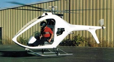
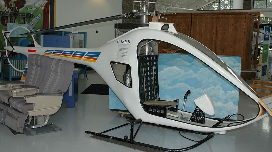
The single-seat C-122 Rainbow helicopter was a design of Russell Chadwick, and was intended to be available in kit form for amateur construction. Powered by a 40 hp Rotax 503 two-stroke piston engine, the prototype started tethered tests late 1985 and was mainly intended as a proof of concept/technology demonstrator.

The design consists of a fibreglass shell enclosing a truss structure to which the engine, rotor mast, landing gear, and pilot’s seat were attached. The skid-type undercarriage could be quickly fitted with wheels for ground-handling, or floats for operations from water.

A prototype was constructed in 1985, and publicly unveiled at the Helicopter Association International annual convention the following year. Flight testing continued through 1987, with deliveries anticipated for that Autumn.

In 1986 Chadwick formed Chadwick Helicopters International, Inc. at Sherwood, Oregon for development, marketing and production of the type in ready-to-fly form. These were to have a longer tail boom, new rotor blades and a tail rotor guard ring, but reportedly only two C-122S machines were built and further development was halted.

Chadwick C-122
Engine: Rotax 503, 40 hp
Rotor diameter: 18 ft 6 in (5.64 m)
Rotor disk: 268.8 sq.ft (24.97 sq.m)
Length (rotors turning): 22 ft 6 in (6.86 m)
Length: 19 ft 0 in (5.79 m)
Height: 7 ft 2.25 in (2.19 m)
Weight empty: 253 lb (115 kg)
Weight loaded: 500 lb (227 kg)
Max speed: 94 mph (151 kmh)
Cruise speed: 74 mph (119 kmh)
Climb: 945 ft (288 m)/min
Service ceiling: 13,480 ft (4,110 m)
Range: 120 mls (193 km)
Seats: One pilot

CGS Falcon        

Falcon V

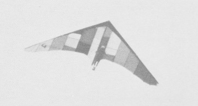
The Falcon V is a second generation high performance glider that features good penetration and high speed coupled with good low speed and low sink rate. It has no tendency to drop a wing in stalls and is very stable in slow speed landings. It tends to mush considerably before stalling.

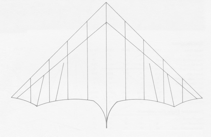
The king post allows the king post tubing to be simply unplugges for replacement. The Falcon V incorporates and elliptical planform and the shape on the wing tips is maintained by use of radially arranged battens in the wing tips. A S-shaped keel adds camber and reflex to the sail. The control bar bracket allows the spar to fold up umbrella-type setup without requiring tools. Deflexers are used. Seat or harness were optional, as was negative or inverted deflexer blades.

The airframe is made from 6063-T832 1.5in x .049 or 1.75in x .049 (depending upon size and model) certified aluminium tubing, bright dipped and anodised for a chrome-like finish. Exterior sleeving is 6063-T832 1 5/8in x .058 or 1 7/8in x .058. Full bushings throughout with dowelings are used in high stress areas. Spar saddles are used.

Rigging cable is 3/32in 7×7 302 plastic coated stainless steel. Cable ends are double nico presses utilising stainless steel thimbles. Turnbuckles are aircraft grade. All hardware is aircraft quality, and all tangs, kingpost bracket, shackles, and rounded nose plate are stainless steel.

The sail is made from Howe & Bainbridge 3.8oz stabilised dacron, in 11 colours or combinations. All seams are double zig-zag stitched and stress points are reinforced. The sail is cut for wing spar deflection and has utilised keel pocket construction. A large leading edge pocket is 18in at the nose tapered to 6in at the wing tip.

The pilot support system has dual rigging for either prone or seated flying.

Leading edge: 20 ft
Keel length: 15 ft
Wing span: 32 ft
Wing area: 195 sq,ft
Aspect ratio: 5.25
Nose angle: 105˚
Sail billow: 1.7˚
Weight: 44 lb
Pilot weight: 140-200 lb
Takeoff speed: 14 mph
Stall speed: 15 mph
Max speed: 44 mph
Best glide ratio (L/D): 8-1
Best L/D speed: 23 mph
Min sink: 225 fpm

Leading edge: 22 ft
Keel length: 17 ft
Wing span: 34 ft
Wing area: 220 sq,ft
Aspect ratio: 5.25
Nose angle: 105˚
Sail billow: 1.7˚
Weight: 46 lb
Pilot weight: 170-225 lb
Takeoff speed: 14 mph
Stall speed: 15 mph
Max speed: 44 mph
Best glide ratio (L/D): 8-1
Best L/D speed: 23 mph
Min sink: 225 fpm

Leading edge: 18 ft
Keel length: 13 ft
Wing span: 29 ft
Wing area: 160 sq,ft
Aspect ratio: 5.25
Nose angle: 105˚
Sail billow: 1.7˚
Weight: 42 lb
Pilot weight: 110-140 lb
Takeoff speed: 14 mph
Stall speed: 15 mph
Max speed: 44 mph
Best glide ratio (L/D): 8-1
Best L/D speed: 23 mph
Min sink: 225 fpm

CGS Spitfire

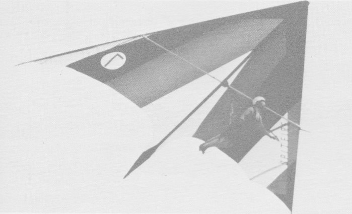
The Spitfire was one of the highest performing standard gliders of the time. Performance was equal to that of Intermediate gliders and some of high performance, with a glide ratio of 6.5-1. The Spitfire offered extreme stability with the performance.

The stinger tail give the directional stability at low speeds. The Spitfire has no tendency to spin off or drop a wing when landing.

The Spitfire was available in two versions: Standard Set Up sets up like most other gliders having a one piece spar, with no tools necessary taking 8 minutes, Quickie Set Up opens like an umbrella, taking about 60 seconds. Nothing comes off the glider, not even the control bar. The Spitfire has a J-wire for defining the S-shaped keel, Dual rigging for either prone or seated flying, swing down deflexers for increased maneuverability, and holes for centre of gravity adjustment.

The airframe is made from 6063-T832 1.5in x .049 certified aluminium tubing, Reinforced sleeves are 6061-T6 1in x .058 tubing. All tubing is bright dipped and anodised. Spar saddles are used wherever there is tube to tube contact. All hardware is aircraft quality and all tags are stainless steel. Plastic king post fittings allow the kingpost to be plugged in or out for easy replacement. A stainless steel king post bracket is fitted.

Rigging is 3/32in 7×7 pastic coated stainless steel cable. Cable ends are double nico pressed utilising stainless steel thimbles. Cable tensioners are used on upper rigging.

The sail is Howe & Bainbridge 3.8oz stabilised dacron in eleven colours combination. 12in leading edge pockets tapered to 6in at the wing tips.

17×15
Leading edge: 17 ft
Keel length: 15 ft
Wing span: 23 ft
Wing area: 150 sq,ft
Aspect ratio: 3.5
Nose angle: 90˚
Sail billow: 3.5˚
Weight: 37 lb
Pilot weight: 100-130 lb
Takeoff speed: 14 mph
Stall speed: 16 mph
Max speed: 40 mph
Best glide ratio (L/D): 6.5-1
Best L/D speed: 24 mph
Min sink: 285 fpm

18×16
Leading edge: 18 ft
Keel length: 16 ft
Wing span: 25 ft
Wing area: 180 sq,ft
Aspect ratio: 3.5
Nose angle: 90˚
Sail billow: 3.5˚
Weight: 39 lb
Pilot weight: 130-160 lb
Takeoff speed: 14 mph
Stall speed: 16 mph
Max speed: 40 mph
Best glide ratio (L/D): 6.5-1
Best L/D speed: 24 mph
Min sink: 285 fpm

20×18
Leading edge: 20 ft
Keel length: 18 ft
Wing span: 28 ft
Wing area: 225.5 sq,ft
Aspect ratio: 3.5
Nose angle: 90˚
Sail billow: 3.5˚
Weight: 42 lb
Pilot weight: 150-210 lb
Takeoff speed: 14 mph
Stall speed: 16 mph
Max speed: 40 mph
Best glide ratio (L/D): 6.5-1
Best L/D speed: 24 mph
Min sink: 285 fpm