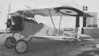
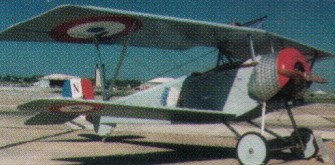
An 87% scale replica first displayed at Oshkosh in 1984 after a hurried 10 hours of serious test flying before being loaded on a trailer for the trip. Construction drawings includes more than 100 pages of dimensional drawings, assembly sketches and construction notes, in 9 x 12 format The Baby Nieuport is an outwardly accurate reproduction with handling characteristics much like the original World War I fighter. Special construc¬tion techniques make the best use of aluminum tube and sheet for a light, robust structure, capable of meeting ultralight or amateur-built criteria, powered by either a Rotax 447 or 50 hp Rotax 503. With more than 100 pages of dimensional drawings, assembly sketches and construction notes, Circa claim that the aircraft, built from alloy tube and sheet, can be put together in around 500 hours. Tubes 6061-T6 Gussets / fittings 2024 – T3 Loops, spins, Split S and a 7000ft power dive were performed on C-IRCA but aerobatics are NOT recommended. A CIRCA Reproduction Nieuport 11/17 features 6061 tube, pop rivet construction. Average cost in 2008 was $6,000.00.
Engine: 1835cc VW 60HP Span: 21’5″ Length: 16’5″ Empty Weight: 300 LBS Useful Load: 300 LBS Wing Area: 114 SQ. FT. Seats: 1 Take Off Distance: 250 FT Stall: 33 MPH Cruise: 60 MPH Rate Of Climb: 650 FPM
Nieuport 11 EXP Engine: Rotax 503, 46 hp. HP range: 22-50. Reduction 258:1 Propeller (flight) 72×33 Height: 7.5 ft. Length: 16.5 ft. Wing span upper: 21.5 ft. Wing span lower: 20.2 ft Wing area: 114 sq.ft. Chord Main Wing 3.6 ft Chord Sub Wing 2 ft Span Elevator 8.2 ft Weight empty 254 to 300 lbs Fuel Capacity 5 to 12 Gal US. Gross: 675 lbs. Top Speed 85 MPH Never Exceed (Vne) 95 MPH Cruise: 80 mph. Range: 200 sm. Stall: 32 mph. ROC: 850 fpm. Take-off dist: 125 ft. Landing dist: 250 ft. Service ceiling: 10,000 ft. Seats: 1. Landing gear: tail wheel. Take off run 250 ft Landing Roll 225 ft G Factor (@ 550 lbs) +6/ – 2.8
Nieuport 11 UL Engine: Rotax 447, 40 hp. HP range: 22-40. Speed max: 77 mph. Cruise: 64 mph. Range: 75 sm. Stall: 27 mph. ROC: 650 fpm. Take-off dist: 200 ft. Landing dist: 250 ft. Service ceiling: 10,000 ft. Fuel cap: 5 USG. Weight empty: 250 lbs. Gross: 550 lbs. Height: 75 ft. Length: 16 ft. Wing span: 21.5 ft. Wing area: 114 sq.ft. Seats: 1. Landing gear: tail wheel.
Engine: Rotax 503, 48 hp Wing span: 7.16 m Wing area: 11.6 sq.m MAUW: 272 kg Empty weight: 125 kg Fuel capacity: 50 lt Max speed: 135 kph Cruise speed: 115 kph Minimum speed: 48 kph Climb rate: 3 m/s Seats: 1 Plan price (1998): $139
In 1959 a twin-float seaplane version was being tested. Originally a cantilever monoplane, the Hydro-Kurir features single bracing struts, the licence-built 155 hp Walter Minor 6-III engine has a redesigned cowling, and the wings raised above the upper fuselage contour. The Hydro-Kurir is actually the fifth Kurir built (50005).
Length: 32.48 ft / 9.9 m Height: 11.483 ft / 3.5 m Wingspan: 46.752 ft / 14.25m Max. speed: 94 kts / 175 kph Service ceiling: 15092 ft / 4600 m
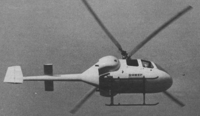
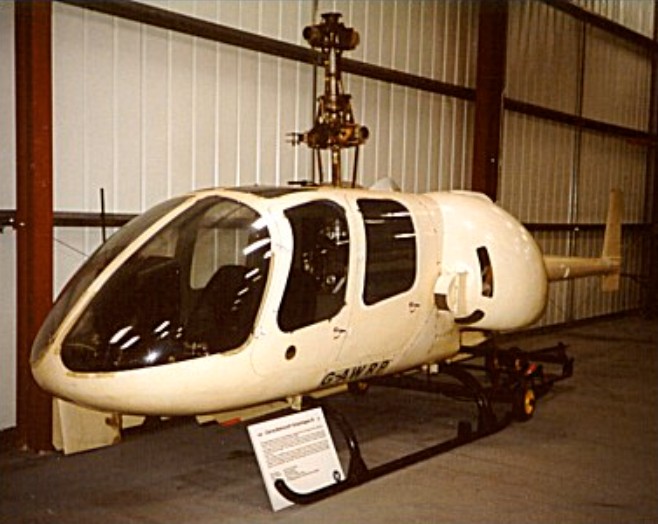
J.Weir maintained a working association with J.S.Shapiro, and in 1961 63 Servotec built a man carrying helicopter model to embody Weir’s ideas of a non stalling rotor, which emerged from many years of model tests. In the course of this collaboration, Weir became aware of the CR Twin development and in 1965 decided to give this development financial support. This combination of interests was cemented in a take over of Rotorcraft Ltd by the Cierva Autogiro Co, which was thereupon renamed the Cierva Rotorcraft Co. The largest shareholders were Weir and Shapiro. The design for a four seat helicopter was shaping up during 1965, and in 1967 the Ministry of Technology awarded a research contract as a partial contribution to test some novel features. Also in 1967 construction of the prototype began, and the first flight took place in August 1969. In the same year Servotec Ltd was taken over by Cierva Rotor¬craft Ltd. Servotec, with its design and inspection approval, continues development work on the CR Twin helicopter and also work under contract to several organisations, including Canadair, Boeing Vertol and Bell. The CR Twin retains the basic layout of two engines driving two contra rotating coaxial rotors, as this was con¬sidered to be the only configuration in which the aims of twin engined safety, simplicity and efficiency could be attained at a low first cost. When the aircraft was designed the only means of achieving the desired performance at a low cost was by the use of piston engines. The turbine engines then available, and indeed still available several years later, were too costly, required a further reduction stage in the main gearbox and had an excessive fuel con¬sumption in cruise. Two prototypes were built, using Rolls Royce Continental O 300 engines of a nominal 145 bhp each. Designated CR.LTH-1 (otherwise known as the CR-Twin) and the first aircraft, G-AWRP, first flew in 1969 followed by G-AXFM (GB-2) later that year, and a third pre-production machine, G-AZAU (GB-3) in mid-1971. This latter aircraft was fitted with 210hp Continental IO-360-D engines, and the production variants were to be the CR.420 with 210hp Continental TSIO-360-A engines and the CR.640 with 320hp Continental Tiara T6-320 engines. These aircraft were used to demonstrate the practicability of the rotor and airframe, but the lower engine power actually avail¬able was inadequate to permit single engined flying. Test flights showed that the low speed handling was easier than with conventional helicopters (having a single main rotor and an anti torque rotor). No difficulties were encountered when engaging rotors in wind speeds up to 35kt. Adequate yaw control was available for normal helicopter manoeuvres, and no control difficulties were met in side¬ways flight at 25kt or in quick stops. A maximum speed of 90kt IAS was attained using less than maximum power, and full autorotation was achieved. The first pre production CR Twin was under construc¬tion in Servotec’s workshops at Redhill in 1972. For its initial flight trials this aircraft was to be fitted with normally aspirated Rolls Royce Continental IO 360s of 210 bhp each. An extremely simple mechanical layout was chosen for the CR Twin. The engines are mounted at about 400 to the fore and aft axis, each driving into the main gearbox through a short drive shaft and combined centrifugal clutch and free-wheel unit. A single stage reduction main gearbox is used, comprising only two input pinions and two output crown wheels the upper of which drives the lower rotor and the lower the upper rotor. The engines, gearbox and rotors are mounted as a combined power/lift group in a separate tubular sub-frame. The rotor is controlled manually by the pilot with no servo assistance being provided. The blades are of a symmetrical untwisted section so that the same spare rotor blade can be fitted to either the upper or the lower rotor, should a blade be damaged in service. Each main rotor blade has a hollow main spar of “compressed wood,” a plastic material reinforced with wood fibres, to the leading edge of which is bonded a stainless-steel anti-erosion strip and within which nose-balance weights are fitted. A blade carcass of glass-fibre cloth of increased thickness towards the blade root is bonded to the main spar aft of the erosion strip, and is injected with polyurethane foam in order to stabilise the trailing-edge section. The canopy, cowlings, Tail-cone and fairways are all constructed of glass-fibre and are mounted on a simple light-alloy platform that also provides mountings for the undercarriage, the subframe supporting the complete power-lift group, the controls, fuel system and instruments. A feature of the helicopter is the ease with which the canopy, cowlings and tail cone can all be quickly removed in order to simplify major servicing operations. The design has followed the sealed-maintenance concept by which field unit assemblies can be exchanged quickly without exceptional skill or facilities.
Development was eventually abandoned in 1975 due to lack of further financial backing.
CR Twin 420 2 x Continental TSIO 360A, 210 h.p. Rotor diameter: 10.06m Fuselage length: 8.58m Max take-off weight: 1564kg Max speed: 222km/h Cruising speed: 193km/h Blade section Naca 00 symmetrical Mean chord 8in tapered. Fuel cap: 65 Imp gal (295 lt). Baggage capacity (rear fuselage): 16 cu ft, 0.453 cu.m, (rear cabin), 47 cu.ft, (1.34cu.m).
CR Twin 640 2 x Continental Tiara T6-320, 320 h.p. Rotor diameter: 10.06m Fuselage length: 8.58m Max take-off weight: 1564kg Max speed: 222km/h Cruising speed: 193km/h Blade section Naca 00 symmetrical Mean chord 8in tapered. Fuel cap: 65 Imp gal (295 lt). Baggage capacity (rear fuselage): 16 cu ft, 0.453 cu.m, (rear cabin), 47 cu.ft, (1.34cu.m).
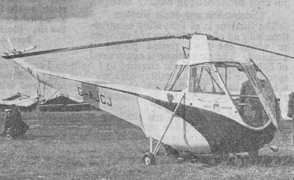
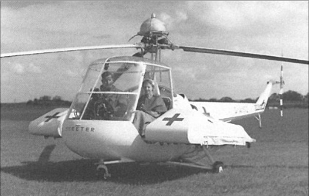
The prototype Skeeter helicopter was designed by the Cievra Autogyro Company as the W14 Skeeter 1 with a 106hp Jameson FF-1 engine and first flew on 8 October 1948 (G-AJCJ), but early development aircraft were under-powered and suffered from resonance problems. The Skeeter had a small, steel tube fuselage structure with a semi-monocoque tail boom section. The three-blade main rotor had metal spars with wooden ribs and a fabric skin, and the two-blade tail rotor was entirely of wood. All the aircraft had tricycle landing gear, although some tests were done with skids.
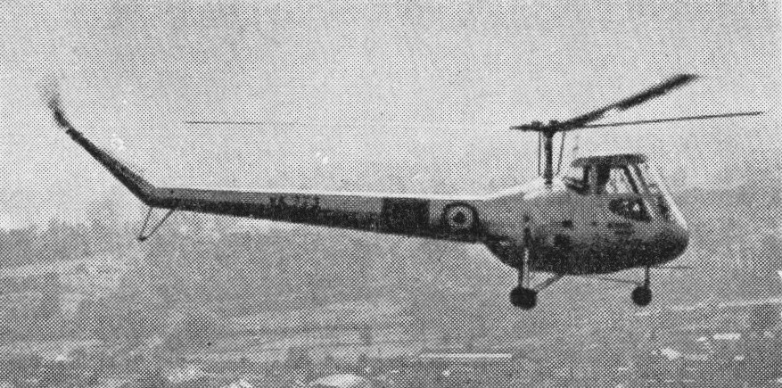
A second machine, the Skeeter 2 G-ALUF, was flown on October 20th, 1949, in which the most important of several design changes were the employment of a 145hp Gipsy Major 10 engine, increased rotor diameter and a slightly longer tailboom of circular instead of triangular cross-section. Two further-modified Skeeter 3’s were begun by Cierva which were completed by Saro, for evaluation by the Ministry of Supply, after the latter company had acquired Cierva in January 1951. Two Mk. 3 (Gipsy Major 10) and one Mk. 4 (Bombardier 702) were constructed for Ministry of Supply evaluation. The two Mk. 3’s were later fitted with Bombardier engines, and re-designated Mk. 3B. One similar machine was completed as the Skeeter 4.
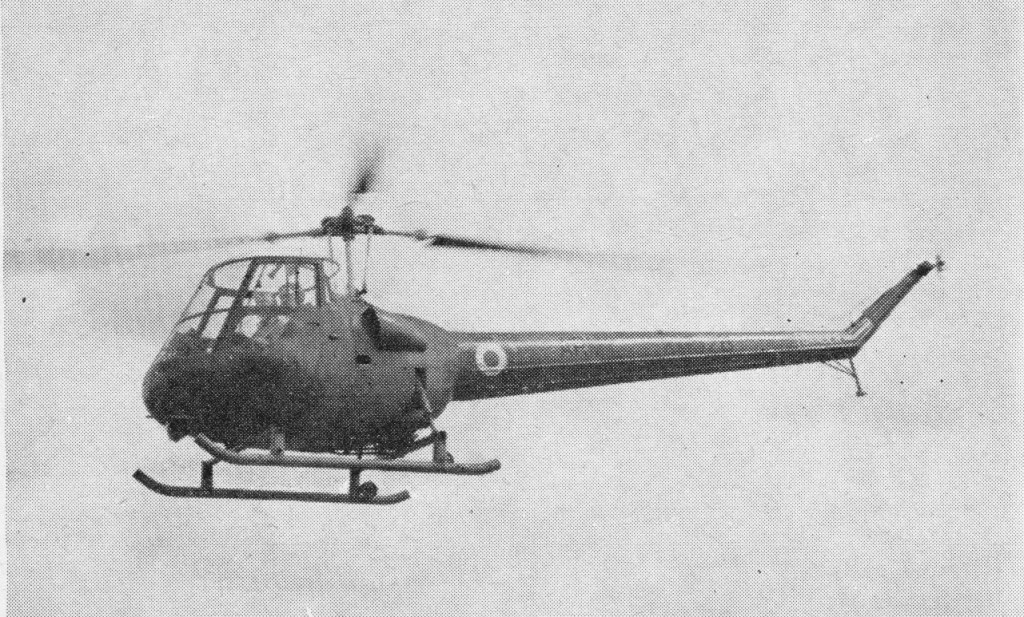
During 1960 a new skid undercarriage was adopted on the Skeeter for the British Army in place of the wheels previously fitted.
Saro’s two Skeeter 5 prototypes, built as a private venture, was essentially similar apart from instruments and minor controls such as the positioning of the rotor brake, they differed in detail from the prototype Mark 2 Skeeter. The Mark 5 has a 190 b.h.p. Blackburn Cirrus Bombardier 704 engine, while the Mark 3 has a 180 b.h.p. Bombardier 702. The engine is fan cooled with a belt drive. They were the first machines of the series to be really free of the ground resonance problems which had beset the earlier prototypes. In 1956 the Skeeter 5’s were refitted with 200hp Gipsy Major 201’s.
In its civil form, the Skeeter Mark 5 has a 27 gallon fuel tank, which gives an endurance of about three hours, and a further 11 gallons may be carried in an auxiliary tank. The rotor and control system are simple with the three blades being built up on tubular steel spars, with ply ribs and fabric covering. Each blade weighs in the region of 45 lb. The tail rotor of the Mark 3 differed from that of the Mark 5 in having only two blades.
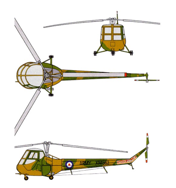
The government-sponsored Skeeter 6 had a 149kW Gipsy Major 30. The power of these engines is much the same but the latter version is a little heavier, carrying more payload and having a higher cruising speed. The Skeeter is built up from four sections the tail cone, complete with rotor, the rear all metal fuselage boom, the centre section, complete with engine, and the cockpit. This seats two side by side with full dual control and instrumenta¬tion.
The Skeeter Mk.6 made overseas appearances at Paris and Stuttgart in June 1956.
Skeeter Mk.6
After pre-service trials with the Skeeter 6 prototypes, initial production orders were given for two basically similar versions with the Gipsy Major 200 engine. These were the four Skeeter 6A, ordered for the Army Air Corps as the AOP Mk.10, and one Skeeter 6B as the T Mk.11 dual-control trainer for the RAF. Follow-on orders were placed later for the Skeeter 7A (AOP Mk.12) and 7B (T Mk.13), which differed chiefly in having 215hp Gipsy Major 215 engines. The Skeeter 7 was also the subject of a small export order, the Federal German Army and Navy ordering eleven and four as Mk.50 and Mk.51 respectively. Final variant was the Skeeter 8, basically an adaptation of the 7 for commercial operation. Three were built for C. of A. tests, but no civil orders ensued and Skeeter production came to an end in 1960 (by which time Saunders-Roe had become part of the Westland group) after a total of seventy-seven aircraft had been built.
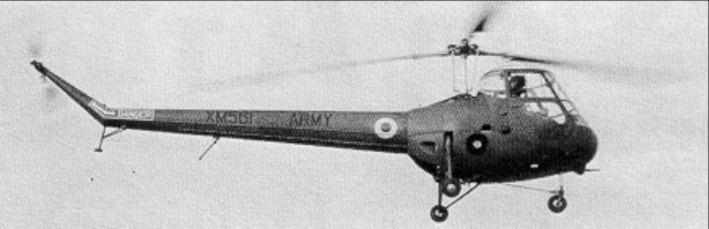
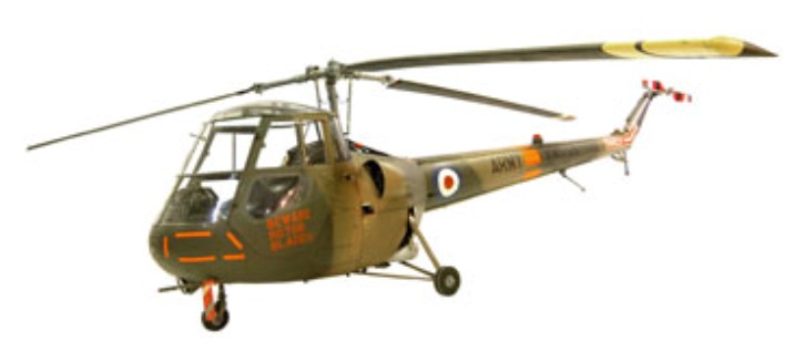
The Skeeter was the first helicopter to enter British Army Air Corps service, replacing fixed-wing Auster aircraft.
The definitive military version was the AOP12 and deliveries began in June 1958. In the three years this version was in production a total of 64 were built in three separate batches. The Saro Skeeter AOP 12 was a two-seat reconnaissance and artillery-observation-post light helicopter which served with the British Army Air Corps between 1957 and 1967. It was powered by a de Havilland Gipsy Major Type 140 piston engine, delivering 215 bhp at 2850 rpm. It had a cruising speed of 76 knots, a service ceiling of 12800 feet and a range of 160 nautical miles.
In 1957 a small number of Skeeter AOP 10s were delivered to the Army and a T.11 to the RAF and about 50 AOP 12s and T13s were delivered in 1959.
A small number of Skeeters, designated Marks 50 and 51, served in Germany. The German Army and Navy received six and four respectively, which were transferred to the Portuguese Air Force in 1961 but never flown.
Of the fifty or so Skeeters supplied to the British services, the AOP 12’s served mostly at the Army Air Corps Training School, while the RAF T13’s were allocated to the Central Flying School and to No.651 Squadron. Ten of the German Skeeters were handed over in July 1961 to the Forca Aerea Portuguesa, with whom they were still in service in 1968. Dual controls are fitted as standard in all Skeeters. During their early life various Skeeter prototypes were used to flight-test a supercharged Gipsy Major engine, a Blackburn Turmo shaft turbine, and a Napier rocket-powered tip-drive system.
Skeeter with rocket engines at the tip of each blade
With only a single crewman aboard, the Skeeter could be flown in a casualty evacuation role with a stretcher pannier supported on each side of the cabin.
Saunders-Roe Skeeter Mk 6 ambulance (equipped with Napier NRE.19 boost system, rocket-fuel tank above hub)
Most Skeeters were replaced by Scout helicopters in 1967 and 1968 having served with four Army Air Corps Squadrons.
Most Skeeters were replaced by Scout helicopters in 1967 and 1968 having served with four Army Air Corps Squadrons.
Saro Skeeter 6 Engine: Gipsy Major 30, 186 h.p. Rotor diameter: 32 ft Rotors: 3-blade main; 3-blade tail Fuselage length: 28 ft 5 in Loaded weight: 2,200 lb Ceiling: 11,900 ft Typical range: 260 miles at 101 mph Seats: 2
Skeeter 6A / AOP 10 Engine: Gipsy Major 200
Skeeter 6B / Skeeter T Mk.11 Engine: Gipsy Major 200
Saro Skeeter 7A / AOP 12 Engine: de Havilland Gipsy Major Type 140, 215 bhp at 2850 rpm Cruising speed: 76 knots Service ceiling: 12,800 feet Range: 160 nm Seats: 2
Saunders Roe AOP 12 Skeeter Engine : De Havilland Gipsy Major 200 Mk 30, 200 hp Length: (blades folded) 28 ft 5 in Length with rotors turning: 8.66m Fuselage length: 26.509 ft / 8.08 m Rotor diameter: 32 ft / 9.75 m Height: 2.29m Empty weight: 780kg Max take off weight: 2200.6 lb / 998.0 kg Max. speed: 87 kt / 162 km/h Range: 186 nm / 345 km Hovering ceiling, IGE: 1680m Service ceiling: 3900m Crew: 2
7B / T Mk.13 Engine: de Havilland Gipsy Major Type 140, 215 bhp at 2850 rpm
Skeeter 8
Skeeter Mk 50 Main rotor diameter: 9.75m Maximum speed: 267km/h
Skeeter Mk 51 Main rotor diameter: 9.75m Maximum speed: 267km/h
In September 1945 Pest Control Ltd had discussed the last possibility with Cierva and the W.11 design was modified to meet this role. As a result, Cierva received a development contract for one W.11 in July 1946, drafted to Specification E.19/46, and a second was ordered in early 1947. Cunliffe-Owen Aircraft Ltd were contracted to build the two aircraft at Southampton/Eastleigh Airport under the technical and financial control of the Cierva company.
1948
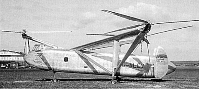
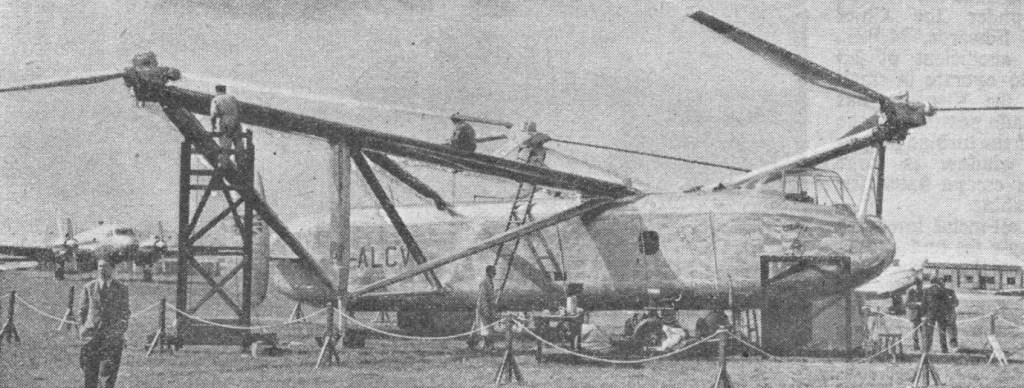
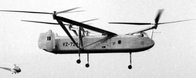
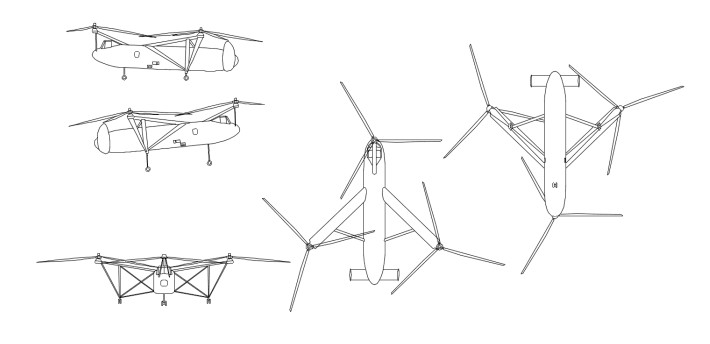
The Cierva W.11 Air Horse, built in 1948, featured three tri-bladed rotors mounted on outriggers from the fuselage and driven from a centrally-installed engine. Two prototypes were built for the British Ministry of Supply.
Power from a single Rolls-Royce Merlin 24 engine of 1208kW was transmitted through shafting to three-bladed rotors mounted on outriggers, each at the tip of a triangle. All three turned in the same direction, but their plane of rotation was sufficiently tilted to compensate for torque. Each rotor hub had a control spider which ensured cyclic and collective pitch control. The engine with its distribution gearbox to drive the rotors was situated just behind the cockpit in the fuselage. The fuselage was designed to carry twenty-four passengers in a compartment measuring 5.79 x 2.31 x 1.77 metres.
There was a tricycle landing gear, each leg of which was fitted with an oleo-pneumatic shock absorber. Twin fins were carried at the end of a mid-mounted tailplane on the rear fuselage and there was accommodation for a crew of three.
The prototype, the largest in the world at that date, made its maiden flight on 7 December 1948, but shortly after being displayed at the Farnborough Show it crashed, and work did not start on it again until the Gierva Company was taken over by Saunders Roe.
The Colonial Office made a grant of GBP45,000 to assist in the development costs since the type offered prospects of overseas use in the spraying role (total Ministry of Supply development costs were estimated at GBP350,000), but before the second W.11 had flown the first crashed on 13 June 1950, killing the three flight test crew members; the second W.11 never flew and was scrapped in 1960. The designation W.11T was allocated to a project for an enlarged W.11 with two 1208kW Rolls-Royce Merlin 502 engines and the W.12 was a projected freighter development with Rolls-Royce Dart turboprops. Neither of these materialised since by that time Cierva, not having used the number W.13, was involved in development of the W.14 which became the Skeeter and was built by Saunders-Roe Ltd.
Cierva W.11 Engine: 1 x Rolls-Royce Merlin 24, 1208kW Rotor diameter: 14.33m Length with rotors turning: 27.0m Width with rotors turning: 28.96m Max take-off weight: 7938kg Loaded weight: 5507kg Max speed: 225km/h Cruising speed: 153km/h Service ceiling: 8535m Range with max fuel: 531km Crew: 4-5 Passengers: 24
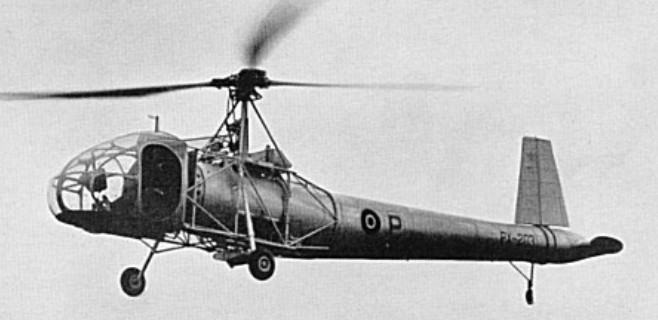
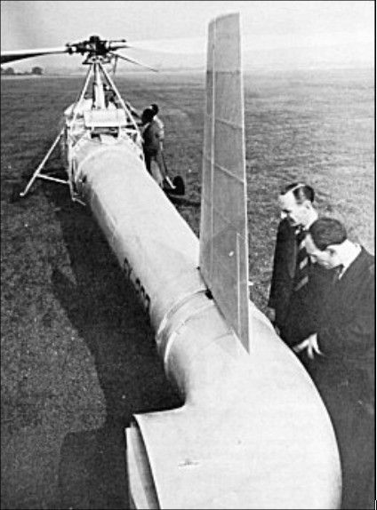
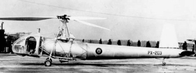
The W.9 was an experimental helicopter to E.16/43, with a three-blade main rotor. Torque compensation was achieved by a jet of air discharged from the port side of the rear fuselage and supplied by a fan which also cooled the engine. The jet was controlled by two vanes. The air from a multi-bladed fan which cooled the engine was ducted through the inside of the fuselage, heated by the exhaust gases and then ejected through an opening on the port side. Two horizontal shutters controlled the flow of this air. The controllable efflux was also used to impart turning movements to the rotorcraft, which had neither fin nor rudder. The multi-bladed variable-pitch fan was coupled to the rudder pedals and thus provided yawing control.
First flown in 1945, only one was built.
W.9 Engine: 1 x Gipsy Six Series II, 155kW Main rotor diameter: 10.98m Max take-off weight: 1200kg