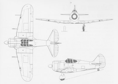
During 1943, following the success of CAC and chief designer Fred David, in rapidly designing and mass producing the small Boomerang fighter for the Royal Australian Air Force (RAAF), CAC began design work on a fully fledged interceptor and bomber escort. Basing on RAAF specification No. 2/42, preliminary work on a very ambitious long-range fighter aircraft started, which received the factory designation CA-15. Layout was an all-metal cantilever low-wing construction with retractable undercarriage and the pilot’s position in a closed cabin. Although the CA-15, also known unofficially as the CAC Kangaroo, bore a superficial resemblance to the North American P-51 Mustang, the CAC design was not based directly on the U.S. aircraft and had quite different performance objectives and dimensions. David had been impressed by assessments of captured Focke-Wulf Fw 190s and intended using a radial engine rather than an inline. Development of the CA-15 was slowed by a recommendation from CAC head Lawrence Wackett, that the company build Mustangs under licence, rather than bear the cost of developing a unique design. By the later stages of its development, it was believed that the CA-15 would have capabilities enabling it to replace the P-51.
In 1943, a mockup of the aircraft was built, although the development process was delayed because the project engineers wanted to accomodate the fighter to low heights. By August 1943, the RAAF accepted the new concept of the machine by specification No. 2/43. In 1944, the mounting of the structural elements of the first prototype started, although in August 1944 the R-2800-21W engine turned out not to be available. At first, the CAC designers planned to use the 2,300 hp (1,715 kW) radial Pratt & Whitney R-2800, with a turbocharger. However, that engine became unavailable, causing further delays in development. The choice fell on British engines; the Rolls-Royce “Griffon” type 120 or 125, although the radial Bristol “Centaurus” had been proposed. The Griffon turned out to have the smallest frontal surface, however, the Griffon 120/125 version had not yet reached its serial production stage, so the British decided to replace it with the 2,035 hp/1,517 kW Griffon 61 version.
Engines for a prototype were leased from Rolls-Royce. The first two copies of the Griffon 61 arrived in Australia in April 1945. The first prototype of the CA-15, as RAAF A62-1001, was completed in February 1946, five months after the end of the war in the Pacific Ocean.
Development was further slowed by the end of the war, with the prototype flying for the first time on 4 March 1946, and was flown by CAC test pilot Jim Schofield, who also flew the first Australian built P-51. The prototype was assigned RAAF serial number A62-1001.
From June 27th, 1946, the prototype performed test flights at the No.1 Aircraft Performance Unit (No.1 APU) at Laverton. Until then, the prototype already had executed 23 flights of joint 16 hours and 45 minutes. It achieved a calibrated level flight speed of 448 mph (721 km/h) at 26,400 ft (8,046 m). Test flights came to an abrupt ending when Flt Lt J. A. L. Archer suffered a hydraulic failure (later found to be a leaking ground test gauge) on approach to Point Cook on 10 December 1946, which left him no choice but to orbit and burn off fuel. The main gear was only halfway down and unable to be retracted or lowered any further but the tail wheel was down and locked. On landing, the tail wheel struck the airstrip first causing the aircraft to porpoise and finally, the airscoop dug in. The aircraft settled back on the fuselage and skidded to a stop, heavily damaged.
The CA-15 after crash landing at RAAF Point Cook
On 19 May 1948 the aircraft was transferred to the Aircraft Research and Development Unit (ARDU), where several farthest test flights were executed. During a flight on May 25th, 1948, Flt. Lt. J. Archer at the controls, the aircraft gained an unofficial speed record, achieving 502.2 mph (803 km/h) on level flight after levelling out of a dive of 4,000 ft (1,200 m) over Melbourne. In May 1950, the machine was transferred to the No. 1 Aircraft depot, where it was scrapped the same month.
By this time, however, it was clear that jet aircraft had far greater potential and no further examples of the CA-15 were built. The prototype was scrapped in 1950, and the engines were returned to Rolls-Royce.
CA-15 Kangaroo Engine: 1 × Rolls-Royce Griffon, 2,035 hp (1,517 kW) at 7,000 ft (2,134 m) Wingspan: 36 ft 0 in (10.97 m) Wing area: 253 sq ft (23.50 sq.m) Length: 36 ft 2½ in (11.04 m) Height: 14 ft 2 in (4.32 m) Empty weight: 7,540 lb (3427 kg) Loaded weight: 9,500 lb (4,309 kg) Max. takeoff weight: 12,340 lb (5,597 kg) Maximum speed: 448 mph (390 knots, 721 km/h) at 26,400 ft (8,050 m) Range: 1,150 mi (1,000 nmi, 1,850 km)on internal fuel Service ceiling: 39,000 ft (11,887 m) Rate of climb: 4,900 ft/min (24.9 m/s) Crew: one Armament: Guns: 6 × 0.50 in. (12.7 mm) machine guns (250 rounds each) Rockets: provision for 10 × rockets Bombs: 2 × 1,000 (450 kg) bombs
During the war with Japan in 1941 Australia decided to produce an emergency fighter based on the Wirraway trainer. Designed and built in 16 weeks during 1942, the CA-12 prototype used the wings, landing gear, and tail unit of the trainer married to a new fuselage and a more powerful 1,200 hp Pratt & Whitney R-1830-S3C4G Twin Wasp 14 cylinder twin row radial engine from the DC-3.
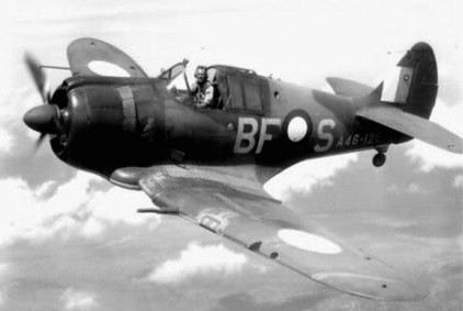
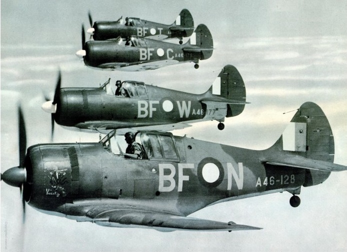
No actual prototype was produced. The first five production aircraft were already under construction before the first aircraft flew on 29 May 1942 (Test pilot Ken Frewin flew A46-1). The first Boomerang Mk 1 fighters entered service in October 1942. Following the flight of the first Boomerang, a further 249 Boomerangs were constructed under four separate contracts between 1942 and 1945. As production progressed, many improvements and modifications were incorporated, and the various standard versions were grouped under three CAC designations: CA-12, CA-13 and CA-19. The last 39 CA-19 Boomerang Mk II were completed as recconnaissance fighters.
CA-12
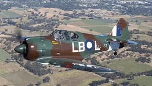
A high performance prototype, the CA-14 A46-1001 was built with a turbo-supercharger. This same aircraft was later streamlined and fitted with a square-cut tail assembly and became the CA-14A. The RAAF accepted the first Boomerang, A46-1, on 15 July 1942, and the last aircraft, A46-249, was delivered on 1 February 1945. Initial pilot conversion was carried out with No 2 Operational Training Unit at Mildura, and these pilots formed the first operational units, Nos 83, 84 and 85 Squadrons. The first enemy contact was made on 16 May 1943, when Boomerangs from No 84 Squadron intercepted and drove off three Betty bombers. For many months, the Boomerangs successfully carried out many similar sorties until replaced by Kittyhawks and Spitfires. Relegated to the army co-operation role with Nos 4 and 5 Squadron, the Boomerangs soon established a strong reputation for effective strikes throughout New Guinea, the Solomon Islands, and Borneo; particularly so in co-ordinated operations with RNZAF Corsairs. A Boomerang at No 1 Aircraft Performance Unit was modified to take two seats; the second position was placed inside the fuselage behind the pilot and was used by an observer to record instrument and performance data. Altogether, 250 Boomerangs were built and the various versions included 105 CA-12s, (A46-1/105), 95 CA-13s (A46-106/200), 49 CA-19s (A46-201/249), whilst the sole CA-14/CA-14A was numbered in the prototype range as A46-1001.
CAC Boomerang A46-63
The standard production CA-12/13/19 Boomerang’s Pratt & Whitney R-1830 Twin Wasp power plant was not supercharged sufficiently to permit adequate high-altitude operations. Full-throttle height, in high blower at military power, being only 13,500 feet. To overcome this deficiency, a turbo-supercharger installation was engineered and fitted into A46-1001, the suffix – 1001 allotted to all Australian military prototypes.
Initial layout, under the name, ‘Turbo Boomerang Interceptor’, was shown on a GA drawing dated 8 January 1942, so that early thought was being given to the altitude deficiency inherent in the use of the standard Twin Wasp. A CA-13 airframe was taken off the assembly line at an early stage of production and converted to suit the installation, (attempting to fit the supercharger and ancillaries to a completed aircraft being too demanding).
CA-14
Engineering commenced in July 1942 with Ian Ring, Ian Fleming, and Alan Bolton working on it. Under Tom Air, Bolton was Project Engineer for the design with CSIR doing the research work on the ducting. A mock-up was built in the No.2 Hangar of the Aircraft Factory. A CAC-built R-1830 S1C3G single-stage Twin Wasp on a longer engine mount, with General Electric B2 exhaust driven supercharger and ancillary equipment from a Boeing B-17E, were made available by the USAAF. Their fitment into the aircraft necessitated considerable redesign.
A Harrison intercooler was fitted into the fuselage behind the cockpit, and an intake for engine and intercooler air was positioned on the fuselage port side. Intercooler air was exhausted over the top of the fuselage through a temperature-controlled shutter behind the cockpit. The supercharger was mounted in the starboard fuselage, the normal exhaust tailpipe being extended down the fuselage to feed the turbine. The standard down-draught carburetor air intake was dispensed with giving it a cleaner top cowl line, while high-altitude magnetos were also fitted. A panel of test instruments was mounted in the rear fuselage, with a 35mm remotely-controlled camera to record in-flight data.
As in production of the Boomerang, compromises had to be tolerated, due to lack of optimum equipment. The best propeller available was a three-blade, eleven-foot Curtiss Electric, with a blade activity factor of 87, which limited climb performance and was 50 pounds heavier than that on the standard Boomerang. The B2 supercharger (as the only one obtainable) had a diffuser design which limited critical altitude by 4,000 to 5,000 feet when used with the R-1830 engine, and a further 500 feet in critical altitude was lost because of a 0.50 in-Hg greater pressure drop across the intercooler, compared with an Airesearch cooler which became available after first flights.
Rate of climb was also restricted because of the necessary use of large opening, conventional cowl gills to induce sufficient cooling flow, and resultant large increase in drag.
While the project was being developed, CAC design engineers had the use of the six RAAF Republic P-43 Lancers at Fishermans Bend for study and evaluation, examination of which was of material assistance.
Through October, work progressed and target date for completion was set at the end of the year. Some trouble was experienced with rudder and elevator control-cable runs which had to be duplicated to meet revised AP970 requirements; bends in the system to clear the ducting compounded this modification.
Although Lawrence Wackett requested Air Board approval, on 4 January 1943, for test pilot Jim Carter to be given some flying in an RAAF P-43B Lancer before flying the CA-14, it was advised that there was not one ‘conveniently available’. Instead, Flt Lt John Holden, the RTO at CAC, who had both Lancer and Boomerang experience, was nominated. (six P-43B reconnaissance fighters were allotted for Australian use, as PRU aircraft).
Ian Ring wrote, on 29 November 1986, ‘I was responsible for the turbo-supercharger installation in the CA-14A. I seem to recall seeing an American installation, but I do not remember getting any significant help from it, other than a general picture. Our installation and turbine performance data came from Pratt & Whitney. The problem was mainly one of accommodating the turbine in the appropriate position in the exhaust system, with suitable heat and fire isolation, and designing the inlet manifolds. The result was a spectacular rate of climb.’
The initial CA-14 flight was made on 13 January 1943 by Holden (promoted to Squadron Leader in that period). He not only proved the turbo installation, but also carried out comprehensive performance trials, and was commended by Aircraft-Superintendent Hugh Francis in a letter to Wackett, then in the US.
Even if Carter was to have taken over the further test work, as would have been the norm, it was not to be, as he was killed in the CA-4 Woomera crash on 15 January. Subsequently the new company test pilot, Greg Board, who arrived on 10 March, took over the task, and in the letter to Wackett, Francis told of Board’s appointment, stating that he had so far flown at very high pressure, and had been satisfactory in every way.
Precedence was given to assessing the engine installation and aircraft performance, and, with approximately 17 hours of flying by 29 March, the only other aspects noted were that ground handling, take-off, and the stall, were similar to the Boomerang, with better forward visibility resulting from removal of the carburetor air intake on top of the cowl.
At that time, engine overheating was occurring with the use of continuous climb outlet to 20,000 feet, but it was felt that fan cooling, then being planned, would cure this. Turbine exhaust temperature was at 780C, 35C below the maximum permissible, while turbine cooling and lubrication were satisfactory. Initial intercooling deficiency was overcome by removing the two lower cowl gills on the port side, thereby obviating engine cooling efflux inflow to the intercooler. Ignition breakdown at high altitude was overcome by replacing the Scintilla magnetos with Bosch high-altitude types. Further flights revealed that the aircraft was neutral stable in the lateral plane, directionally unstable, and rudder-trim changes with speed were excessive.
To overcome these latter two faults, the fin area was increased and redesigned, while lateral stability was improved by sweeping the wing tips up, as had been done on the Boomerangs. The supercharger installation was considered to be very satisfactory, but, due to the restricted climb, a cable was sent to Wackett on 15 April recommending that he obtain a four-blade eleven-foot propeller for the aircraft, similar to that fitted to the P-51B.
Performance and handling tests, at which time it was fitted with a large spinner, were completed by CAC (including flying to 35,000 feet) and it was delivered to the RAAF in April. On its return from Laverton in May, a new fin and rudder were fitted to further increase vertical area, and these improved the aircraft’s handling qualities as reported by the company test pilot.
It was returned to the RAAF for further evaluation. Board had flown it to 41,000 feet, its upper limit, and found that controllability was then almost non-existent, and that it fell away out of control very easily, (as was to be expected). From the lessons learnt with the CA-14, the same aircraft was developed into the CA-14A, still as A46-1001. Design calculations showed it to have a better all-round performance than the Thunderbolt and the Spitfire VC, comparative operational ceilings (at which rate of climb falls below 1,000fpm) were 34,400 feet, 32,000 feet, and 29,700 feet respectively. With 30 hours of CAC test flying and ten hours of RAAF evaluation on the CA-14, the conversion was carried out through June and July, with the following changes and new equipment scheduled for incorporation.
1) CAC-built R-2000 Twin Wasp replacing the R-1830. (not achieved.)
2) A B9 turbo-supercharger (actually a B13 was fitted).
3) The four-blade 11 foot Hamilton Standard propeller with blade-activity-factor of 113.5.
4) Ten-bladed cooling fan mounted behind the propeller, and driven through the reduction gearing at three times propeller speed.
5) Sliding cowl gills in place of the conventional hinged type.
6) Retractable tail wheel (not achieved).
7) The intake for the intercooler and engine air was fed from directly behind the fan, gaining considerably from ram effect, and also further increasing critical altitude. The ducting was set nearer the fuselage centre line and did not protrude as far out from the fuselage as it did on the CA-14.
8) The Airesearch intercooler. (40 pounds lighter than the Harrison)
9) A bulkhead in the rear fuselage (not achieved, it is believed, unless the auto observer panel was so described).
10) Changes in the oil-cooler installation and ducting.
With the original hinged gills opened, there was a tremendous increase in drag and buffeting and a reduction in controllability and forward vision. To overcome these liabilities, sliding gills were developed on A46-157 and a variable exit orifice, which was capable of controlling the cooling airflow within laid-down limits, was achieved. Operated hydraulically, as were the standard hinged gills, these slid backwards and forwards along a series of rails to alter the exit.
For some reason, the hinged gills were reinstated at some later stage, and were still on the aircraft when it was eventually broken-up. (It has not been possible to find detail of the changes in item 10, necessary because the exit ducting from the oil-coolers could not be allowed to feed the exhausted air into the extended intercooler/engine intake in the CA-14A, on thermodynamic grounds, and so as not to detract from maximum power).
The first graduate from the Sydney University Aeronautical Engineering Course, completed in 1941, was Alan Bolton, who went straight to CAC on Boomerang stressing, and then worked on the CA-14/14A design – he was able to advise in January 1994 that, to the best of his recollection, the outlet had been relocated to the starboard side into the duct which carried the exhaust tailpipe.
However, it is not known how oil-temperature control was effected in such a position, seemingly without the pilot-controlled exit flap, which had been on the port-side of the CA-14 and all production Boomerangs. During the conversion, a further increase in fin area was added, and the centre-section leading edges were straightened and swept forward, thus cutting out the wheel well fairings. During high-speed dive tests, up to 400 mph IAS, on A46-27, shock waves at the fuselage wheel-well junction occurred at about 360 mph by obviating this junction, wind-tunnel tests, showed the shock waves disappeared unti1 420mph was reached.
A limiting dive speed of 410mph was then placed on the CA-14A. Weight increase with these modifications was 100 pounds, making the all-up weight 8,132 pounds. Wackett wrote to DAP Secretary Letcher on 29 June 1943 to recommend production of the CA-14A before CA-17 manufacture could be started. With almost all of the detail parts for the 200 Boomerangs completed, various departments would be out of work within the next two months, and the assembly task would be completed in October.
With at least six months to the start of detail work on the CA-17, dependent on the arrival of information from the USA, and manufacture of the necessary tooling to begin fabrication, at least 200 more Boomerangs could be built, and such was necessary to keep the organisation intact, pending the start of CA-17 work. As there was need for an urgent decision, for either standard Boomerangs or the CA-14A development, he recommended the latter.
It used fully 75% of the tooling for the standard Boomerang, and it was therefore possible to issue production orders for much of the detail parts immediately, while producing tooling for the new parts necessary to suit the supercharger installation. He summarised the project and company hopes in a report which contained the following key points: The CA-14A’s performance would better the Spitfire Vc:
it is sound reasoning to produce a version which can continue until the CA-17 becomes available;
installation of the CA-14A’s turbo-supercharger has been carried out successfully;
the 2000 cubic inch conversion of the 1830 engine, conducted locally on a Lidcombe built engine, has much promise;
after a long series of trials the 40-degree propeller with wooden blades functions perfectly in flight;
the development of the geared cooling fan is sufficiently advanced to enable this feature to be incorporated in the CA-14A. The success of the Focke Wulf 190 is largely due to this feature;
the CA-14A will incorporate a larger fin and rudder and an improved fairing at the leading edge of the centre section. Both of these features have proved advantageous;
the U.S. Army Air Force in Australia has hundreds of superchargers in store, and it should be possible to make a strong case for favourable consideration that sufficient of these be allotted for CA-14A production.
At the 5 July 1943 meeting of the AAC, Wackett emphasised that it was necessary to give immediate consideration to the production to be carried out between the thencurrent Boomerang contracts and the beginning of the Mustang, re-iterating the points made in his letter to DAP, and pointing out that the CA-14A was definitely the best possible aircraft to build until the CA-17 was under way.
Production of 120 further Boomerangs out of a DAP proposed 325 was recommended by the Minister for Aircraft Production on 8 July, with these to have the R-2000 and turbo-supercharger installed as soon as it could be done. However, the War Cabinet authorised only 50; this was not considered worth the extra effort involved for such a small number, and accordingly the CA-14A proposal was dropped. These 50 were built as standard Boomerangs, under the CA-19 contract. The CA-14A was actually completed and flown on about 26 July with the R-1830 sans fan, and a three-blade Hamilton Standard propeller. The R-2000 engine had suffered from bearing failure on test, and was not ready. Although the necessary enquiries had been made overseas for a suitable four-blade propeller, none was procured in time.
This would have resulted in much greater efficiency at climbing speed at all heights above about 15,000 feet, and at maximum speed. A letter from CSIR to Dept of Air (dated 20 August 1943), stated that the CA-14A incorporated many experimental features, in the design of which the CSIR had been actively concerned, and for this reason the RAAF was requested to carry out further detailed tests beyond the Type Trials.
These were to cover intercooler flows and temperatures, engine cooling, fuel consumption, duct pressures, etc, in order to confirm the theoretical figures arrived at. Gp Capt Walter Armstrong (DTS) answered on 27 August, by saying that, although the CA-14A was of great technical interest, alterations in policy and pressure of other work placed further testing of the aircraft in a low-priority bracket. Turbo-supercharging for fighter aircraft had fallen out of favour here and overseas, mainly because of the slow response to throttle opening, and consequent lack of acceleration during combat.
However, if opportunity occurred, tests on the CA-14A were to continue. Both the CA-14A and A46-157 (and A46-27?) were used by CAC as test beds for the prototypes of a CAC-designed-and-built four-blade propeller with high-density wooden blades, a 38 degrees pitch range and 130 pounds lighter than similar metal propellers. Although developed with some success, and intended for, among others, the Mustang, it did not go into production.
A forced landing was made by A46-157 on 5 November 1943, believed to be due to the loss of about six inches off the tip of a blade, the resultant vibration loosened all but one tailplane attachment bolt before the landing could be effected. Just one week later, the CA-14A made a forced landing at Geelong when a bolt on the spinner backplate fractured.
Both of these aircraft were finally handed over to the RAAF in June 1944, fitted respectively with the first production fan and the first experimental one. The original allotment for the CA-14 project was £15,000 and the actual costs incurred until final delivery totalled £16,418/11/5, the engineering hours expended on it amounting to 15,160. The CA-14A was scrapped at the surplus aircraft park at Laverton during 1947 however, its mainplanes were used by ARL in its structural-fatigue research program.
A Boomerang was modified for use in the Australian film “Smithy” but afterwards was parked in a backyard at Blacktown, NSW, Australia.
Commonwealth CA 12 Boomerang Mk.I Engine: Pratt & Whitney R 1830 S3C4G Twin Wasp, 1184 hp Wingspan: 10.97 m (36 ft 3 in) Length: 7.77 m (25 ft 6 in) Height: 3.5 m (11 ft 6 in) Wing area: 230.35 sqft / 21.4 sq.m Weight empty: 5455.2 lb / 2474.0 kg Max take off weight: 7007.5 lb / 3178.0 kg Max. speed: 256 kts / 474 km/h / 296 mph Cruising speed: 226 kts / 418 km/h Service ceiling: 29019 ft / 8845 m Range at 190mph/304kph: 930 mi / 1490 km Wing load: 30.55 lb/sq.ft / 149.00 kg/sq.m Crew : 1 Armament : 2x MK 20mm, 4x MG 7,7mm
CA-13 Boomerang Mk II Engine: one 1,200-hp (895-kW) Pratt & Whitney R- I 830-S3C4-G Twin Wasp radial piston Propeller: Hamilton Standard 3E50 Constant Speed three-blade Diameter: 11′ 0″ (3.35 m) Fuel: Aviation Gasoline 87 Octane Maximum speed 305 mph (491 km/h; 265kts) at 15,500 ft (4,725 m) Initial climb rate 2,940 ft (896 m) per minute Service ceiling 34,000 ft (10,365 m) Range 1,600 miles (2,575 km) Weight empty 5,373 lb (2,437 kg) Maximum take-off 8,249 lb (3,742 kg). Wing span 36 ft 0 in (10.97 m) Length 25 ft 6 in (7.77 m) Height 9 ft 7 in (2.92 m) Wing area 225.0 sq ft (20.90 sq.m) Armament: Two 20mm Hispano or CAC manufactured cannons, Four 0.303in Browning machine guns Fuel capacity Wing Centre Section (2): 45 Imp Gal / 204 Litres / 54 US Gallons Fuel capacity Fuselage Tank: 70 Imp Gal / 318 Litres / 84 US Gallons Fuel capacity jetisonable: 70 Imperial Gallons (318 Lt) Accommodation: 1
When Japan entered World War II in December 1941, the RAAF did not possess a single fighter aircraft for home defence and, consequently, a decision was hurriedly made to produce a local fighter as a stop-gap measure to meet the threatened Japanese onslaught. Fortunately, the Commonwealth Aircraft Corporation already had plans in hand for an interceptor aircraft, and this promising design was ordered into production on 2 February 1942. Thus, Australia’s first single-seat fighter came from an organisation headed by Lawrence Wackett, who was also responsible for the country’s first indigenous fighter, the two-seat Wackett Warrigal Mk II of 1930.
The Wackett was designed specifically for Australian climate conditions, and has a welded chrome-molybdenum steel-tube framework with fabric covering.
The first of two prototypes powered by the DH Gipsy Six engine was flown early in 1940. Owing to the difficulty of obtaining these engines for production aircraft, the design was modified to take the 165 hp Warner Super Scarab 165D radial engine.
The Wackett designed prototype CA-2 Wackett two-seat prototype went into production designated CA-6. Two hundred were then produced for the RAAF.
CA-6 Wackett Engine: 165 hp Warner Super Scarab 165D Wingspan: 37.01ft (11.28m) Length: 25.98ft (7.92m) Height: 9.84ft (3.00m) Empty Weight: 1,909lbs (866kg) Maximum Take-Off Weight: 2,590lbs (1,175kg) Maximum Speed: 115 mph (185kmh; 100kts) Maximum Range: 425 miles (684km) Accommodation: 2
In 1935 the Chief General Manager of Broken Hill Proprietary (BHP), Essington Lewis, visited Europe and formed the view that war was probable. On his return to Australia, concerned at the lack of manufacturing capabilities there and at the possibility of aircraft not being available from ‘traditional’ (i.e. British) sources during wartime, he commenced a lobbying campaign to convince the Australian Government to establish a modern aircraft industry. The government required little persuasion and encouraged negotiations between a number of Australian companies. The outcome of these negotiations, begun in August 1935, was the formation of CAC the following year. Initially the companies involved were BHP, General Motors-Holden Ltd., and Broken Hill Associated Smelter Pty. Ltd. These were joined by Imperial Chemical Industries of Australia and New Zealand Ltd., the Orient Steam Navigation Company Ltd. and the Electrolytic Zinc Company of Australasia Ltd. at the time of CAC’s formation (the company was incorporated in Melbourne on 17 October 1936). By September 1937 a factory had been completed at Port Melbourne. Shortly after the establishment of CAC, Mascot-based Tugan Aircraft was purchased. This led to Lawrence Wackett joining the company; he immediately became the General Manager. In 1935 Wackett had led a technical mission to Europe and the USA to evaluate modern aircraft types and select a type suitable to Australia’s needs and within Australia’s capabitities to build. The mission’s selection was the North American NA-16; with CAC’s modifications this became the Wirraway. CAC also undertook production of the Pratt & Whitney R-1340 engine used in the Wirraway and also built some propellers when supplies from alternative sources became problematic. The North American NA-33, built under license as CA-1 to CA-16 Wirraway for RAAF, starting in July 1939.
Followed by Wackett-designed prototype CA-2 Wackett two-seat trainer, production version designated CA-6.
Company also produced the only Australian-designed fighter to serve in Second World War, the CA-12,13, 14, 19 Boomerang.
Later designs during World War II were the sophisticated Woomera and CA-15, however these types were destined to fly only in prototype form. Postwar products included the prototype CA-22 and production CA-25 Winjeel trainer for the RAAF, the CA-28 Ceres agricultural aircraft, and over 200 North American Mustangs built as CA-17 and 18.
Other, jet-powered aircraft designs in the 1950s and 1960s did not even leave the drawing board, however in 1951 CAC was given the go-ahead to design and manufacture a version of the F-86 Sabre with a Rolls-Royce Avon turbojet and armament. The Sabre was developed and produced concurrently with the indigenous Winjeel trainer, with Sabre manufacture coming to an end in 1961.
In 1964 after a large amount of political lobbying CAC began producing components for the Sabre’s replacement, a version of the Dassault Mirage III, as a subcontractor to the Government Aircraft Factory (GAF). In 1967 CAC commenced licence production of a version of the Aermacchi MB-326 optimised for Australian conditions as Aermacchi M.B. 326H, this programme ended in 1972.
In 1971 CAC joined the small number of aircraft manufacturers which have built both fixed- and rotary-winged aircraft, when it began production of a variant of the Bell Kiowa for the Australian Army and Royal Australian Navy, the last of these was delivered in 1977. The same year CAC embarked on a Life Of Type Extension (LOTEX) programme for the Macchi, which was suffering fatigue problems. The LOTEX programme lasted until 1984. Other contracts included workfor Boeing, Sikorsky, Pratt & Whitney and Hawker Siddeley. Finally specialized in the manufacture and repair of gas turbine engines.
Became a public company in 1975 and CAC became a fully owned subsidiary of Hawker de Havilland in 1985 and was renamed Hawker de Havilland Victoria Limited in 1986. The Commonwealth Aircraft Corporation was renamed AsTA (Aerospace Technologies of Australia) in 1986. This company was purchased by Boeing Australia in 2000.
The Kiowa was the last type built by CAC. The company was part of the Australian Aircraft Consortium which designed the A10 Wamira, but this programme was cancelled in 1985 shortly after the prototype was completed. At the time of purchase by Hawker de Havilland, CAC had begun delivering components for the GAF-built version of the F/A-18 Hornet.
During its existence the Commonwealth Aircraft Corporation produced over 1700 aircraft of all types, including prototypes and aircraft assembled locally from imported components. Of these, almost 550 were examples of aircraft types wholly designed by the company. The designations used by CAC reflected production or design work in fulfillment of different in-house projects or government contracts rather than different types produced (for instance the different designations for the Wackett and Winjeel prototypes compared to their production versions). Early types were given consecutive manufacturer’s construction numbers (c/nos.), while later types (beginning with the production version of the Winjeel) were given c/nos. with the model number as a prefix. Construction numbers 1210 to 1224 appear not to have been assigned. The list of company designations and construction numbers is:
CA-1 First Wirraway production contract; 40 built (c/nos. 1-40). CA-2 Wackett prototypes; two built (c/nos. 101, 102). CA-3 Second Wirraway production contract; 60 built (c/nos. 41-100). CA-4 Woomera prototype; one built (c/no. 435). CA-5 Third Wirraway production contract; 32 built (c/nos. 103-134). CA-6 Wackett production contract; 200 built (c/nos. 235-434). CA-7 Fourth Wirraway production contract; 100 built (c/nos. 135-234). CA-8 Fifth Wirraway production contract; 200 built (c/nos. 436-635). CA-9 Sixth Wirraway production contract; 188 built (c/nos. 636-823). CA-10 Proposed Wirraway variant not built CA-11 Woomera production contract for 105 aircraft. Contract cancelled, only one aircraft flew (101 c/nos. assigned, 1225-1325). CA-12 First Boomerang production contract; 105 built (c/nos. 824-928). CA-13 Second Boomerang production contract; 95 built (c/nos. 929-1023). CA-14 Experimental Boomerang fitted with turbocharger; one built (c/no. 1074). CA-15 Single-seat fighter; one built (c/n 1073). CA-16 Seventh (and final) Wirraway production contract; 135 built (c/nos. 1075-1209). CA-17 First Mustang production contract; 80 assembled from imported components (c/nos. 1326-1405, 1326-1345 also assigned North American c/nos. NA110-34366 to -34385). CA-18 Second Mustang production contract; 120 built, production of a further 50 cancelled (c/nos. 1406-1525). CA-19 Third (and final) Boomerang production contract; 49 built (c/nos. 1024-1072). CA-20 Contract to modify Wirraways for use by the RAN (see CAC Wirraway); 17 modified. CA-21 Third (and final) Mustang production contract for 100 aircraft; contract cancelled, none built. CA-22 Winjeel prototypes; two built (c/nos. 1526, 1527). CA-23 Designation of a two-seat twin-engined supersonic jet fighter design. None built. CA-24 Contract for production of 72 of variant of the Hawker P.1081; none built. CA-25 Winjeel production contract; 62 built (c/nos. CA25-1 to -62). CA-26 Sabre prototype; one built (c/no. 1528). CA-27 Sabre production contract; 111 built (c/nos. CA27-1 to -111). CA-28 Ceres production, built as private venture; 21 built (c/nos. CA28-1 to -21). CA-29 Production sub-contract for wings, fins, rudders, tailcones and engines of GAF-built variant of Mirage IIIE; 101 airframe shipsets and 140 engines built. CA-30 Macchi production contract; 20 assembled from imported components plus 77 built (c/nos. CA30-1 to -97, CA30-1 to -13 and -15 to -21 also assigned non-consecutive Aermacchi c/nos. between 6351 and 6395) CA-31 Jet trainer design; none built (Macchi built instead). CA-32 Kiowa production contract; 12 assembled from imported components plus 44 built (c/nos. CA32-13 to -56, all 56 aircraft also assigned Bell c/nos. 44501-44556). CA-33 Contract for modifications to the RAAF fleet of Lockheed P-3C Orions; installing the Barra Sonobuoy system (developed for the RAAF and Royal Air Force by the Defence Science and Technology Organisation (DSTO)) and associated systems after delivery of each aircraft from the USA; 20 aircraft modified (contract completed as HdHV). CA-34 Designation used for CAC’s participation in the A10 Wamira project. CA-35 Contract for modifications to a Fokker F27 Friendship (registration VH-EWP) to install the LADS system developed by the DSTO (contract completed as HdHV). CA-36 Production sub-contract for the wing pylons, engine access panels, aft nozzle fairings, aircraft-mounted accessory drive gearboxes and engines for the GAF-built version of the F/A-18 Hornet; 73 airframe shipsets and 158 complete engines built, plus parts of another 17 engines (contract completed as HdHV).
Engine types produced by CAC include the:
Pratt & Whitney R-1340 built for the Wirraway. Pratt & Whitney R-1830 built for the Boomerang, Woomera and DAP Beaufort. Rolls-Royce Merlin built for the GAF Lincoln. Rolls-Royce Nene built for versions of the de Havilland Vampire manufactured by de Havilland Australia. Rolls-Royce Avon built for the Sabre and GAF Canberra. SNECMA Atar built for the Mirage. Bristol Siddeley Viper built for the Macchi. General Electric F404 built for versions of the F/A-18 Hornet manufactured by the Government Aircraft Factory/Aerospace Technologies of Australia.
Formed 1988, after acquiring rights to Rockwell Commander 112 and 114 from Gulfstream Aerospace Corporation. First flew in May 1992 new four-seat Commander 114B version, since followed in 1994 by 114TC turbocharged version. Commander 114AT is advanced trainer. Commander Aircraft Company is the latest aviation business in the US to go belly-up (Dec 2002), with the manufacturer of high-performance single-engine aircraft filing for “Chapter 11” bankruptcy protection. The company planned to restructure and will continue to build aircraft
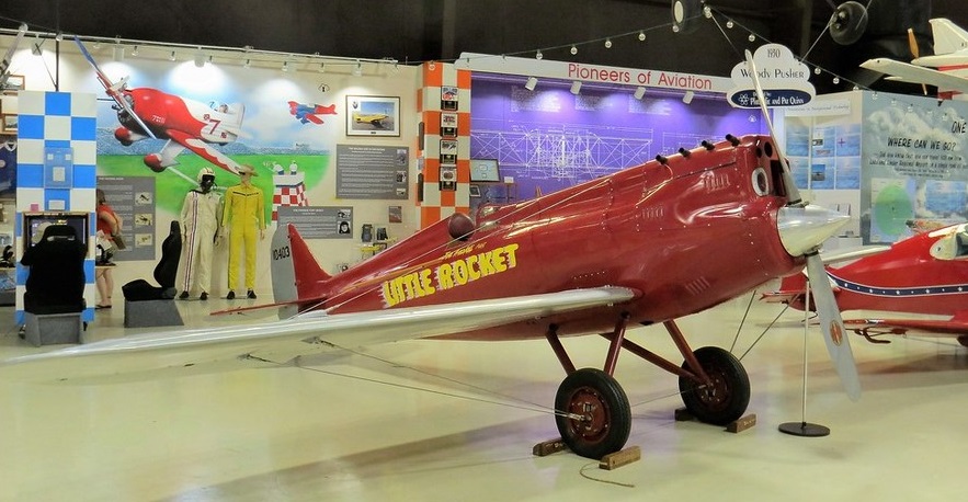
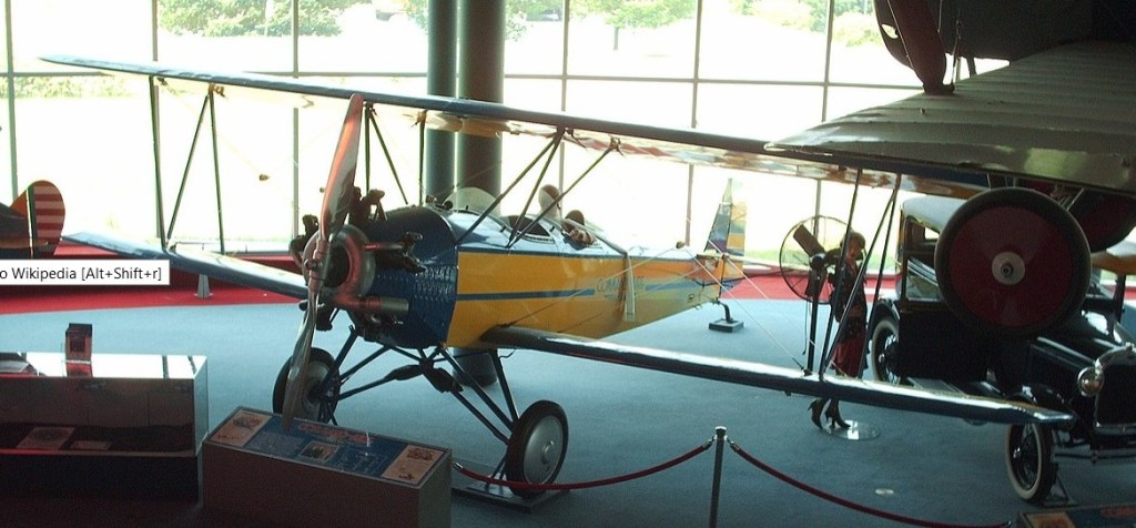
Command-Aire MR-1 Little Rocket Racer N345JA (Reproduction) on static display at the Sun’n Fun Florida Air Museum at the Lakeland Linder Regional Airport in the City of Lakeland Polk County Florida U.S.A.
Command-Aire built one little Rocket Racer. The Rocket was built to compete in the 1930 All American Derby. Equipped with a super-charged 90 hp Cirrus and Lee Gelbach at the controls, running a race course that spanned most of Mid-America, the little Rocket repeatedly recorded ground speeds of 215 mph, its average point-to-point time being in the neighbourhood of 160 mph. The aircraft won the 5,500 mile race and $15,000 prize (a fortune in the depression) with an average speed on 127mph.
The Rocket no longer exists, but Joe Armaldi in Florida built a replica of the racer.
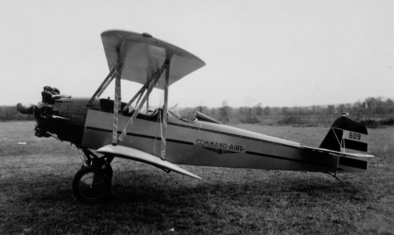
The Command-Aire did not at first appear to offer much of an advancement over the vast multitude of three seat biplanes built around the ubiquitous Curtiss OX-5 engine to similar designs, with similar dimensions and construction methods, many of which were already in production. The basic design was by Morton Cronk, and although it had excellent high altitude capabilities, it was slow. This setback nearly foundered the company before its first aircraft entered production.
Albert Vollmecke, a Heinkel engineer was in the US attempting to find a customer to build Heinkel HD 40 mailplanes under licence for the US market. Seeing that there was little prospect of any sales in the US, he decided to hire on with an American company, Command-Aire.
His first task was to rework the design to provide documentation for the new approval process. While there was only one major visible external difference, he undertook an extensive redesign based on his experience in the much more scientifically-grounded German aviation industry, and to bring the design into line with CAA (now FAA) certification requirements, which involved a lot of submissions, and alterations, and resubmissions before they signed off on it. Many parts had to be redesigned when it was easier to redo the design, than to use the existing design to calculate the necessary strength margins. The most obvious change was a switch from four small conventional ailerons at the tips to two slotted nearly full-span ailerons on the lower wing. This improved low speed control dramatically, allowing lateral control even after the aircraft had stalled – a novelty among American aircraft at the time, and a recurring advertising theme.
The second change was the incorporation of a Phylax fire suppression system capable of putting almost any fire out in flight. The third novelty was the use of a rotisserie type fuselage jig, that ensured accuracy and consistency between the airframes they built, reducing the chance of building an airplane that couldn’t be rigged to fly right. Although Command-Aire’s advertising claims that Vollmecke invented this, he claimed he merely brought the idea from Europe.
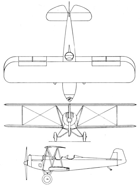
The fuselage was built from welded chromium-molybdenum alloy steel tubes, faired with wooden battens. The top of the fuselage was covered in large metal panels that could be readily opened to provide access, and a compartment for luggage was provided between the cockpits large enough for a suitcase.
The slightly staggered wings were built around solid spruce spars, with spruce and plywood warren truss type ribs. The wings were braced with cables.
The ailerons and the entire empennage were also built from chromium-molybdenum alloy steel tubing, and all controls were actuated through pushrods and bellcranks, with no cables or pulleys used. The ailerons on the prototype were conventional, however on production variants, they extended across nearly the full span on the lower wings only, and had a slot that allowed air to flow over the aileron at low airspeeds and high angles of attack, which helped ensure lateral control even after the wings had stalled. These were not Frise-type ailerons though, but conventional ailerons with a slot at the hinge line.
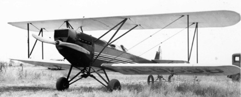
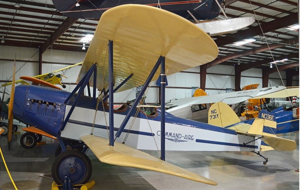
The undercarriage was a split axle type, braced to a steel tube four point pyramid that extended from the belly of the aircraft, with suspension provided with bungee cords which were protected by leather boots. Both cabane and interplane struts took the form of an N and were steel tubing as well. The 3C3 can be distinguished from later types by having an additional strut providing lateral bracing from the forward strut anchor point on the wing, to the lower longeron at the firewall, triangulating the structure. The 4C3 and later types dispensed with this extra strut, and coincided with an extensive redesign that otherwise had few external differences.
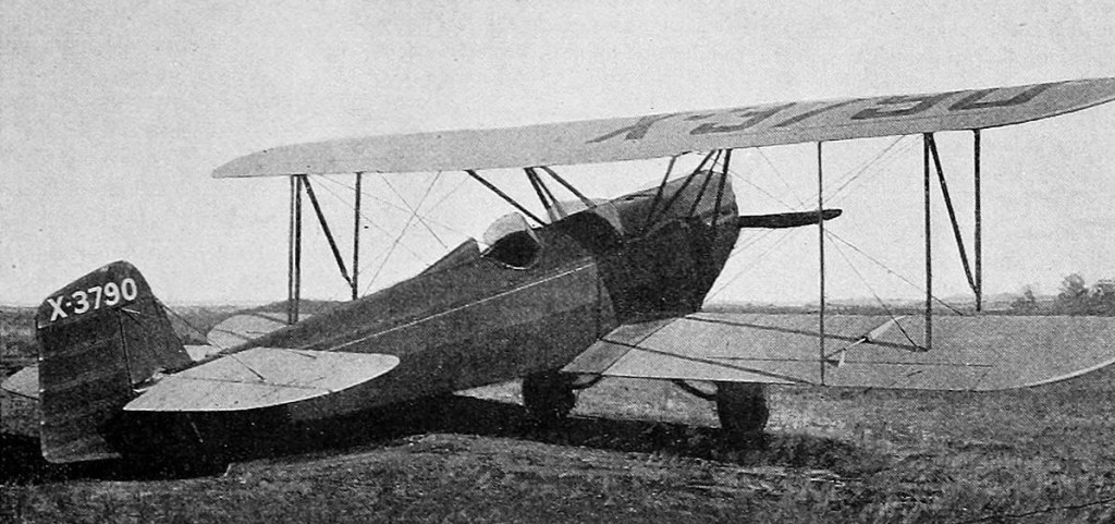
The 3C3 first flew in January 1928 and received certification in July 1928.
Command Aire 3C3 prototype from Aero Digest, February 1928
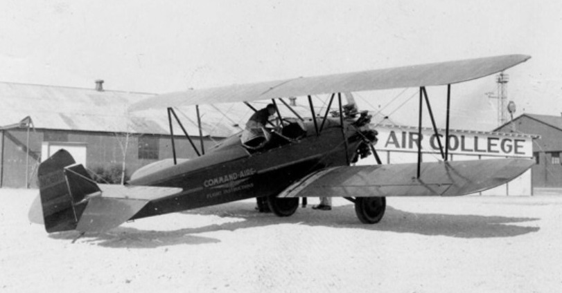
While normally a three-seat design, those aircraft with a T in the designation were built as two-seat trainers specifically for flight instruction, and a crop-dusting version was also sold, with the space in the front cockpit being filled with a large hopper, and the fuel tank relocated to the wing centre section. At least 17 of these were built, with others converted from other variants.
The 3C3 was one of the most pleasant and stable aircraft of the 1920’s. In the companies “hands off” flight demonstration, the fearless pilot would climb out of the cockpit and straddle the turtle deck like a horse while the aircraft cruised the skies, this proved a quite effective sales technique. He turned the aircraft by leaning in the desired direction.
Command-Aire 3C3 NC6688 msn 513 showing salient characteristics, including triangulated cabane that was simplified on later models
The 3C3 is similar in construction to most aircraft of the period and used a war surplus OX-5 engine. One of the notable features was the metal cowls, cockpit and turtle deck which made half the aircraft metal covered–not fabric covered. The aircraft was controlled by push-pull tubes and bell cranks, there were no wires, cables or pulleys.
In another publicity stunt, a flight of over 100 mi (160 km) from San Diego to Los Angeles was made without once using the control stick as all control inputs were through the rudder pedals.
In 1929, the government decided to allow aerobatics (known as stunting at the time), during the Annual Arkansas Air Tour being held in 1929 and so a team of three Warner-powered Command-Aire 3C3-As were formed as “The Blue Devils”, but painted incongruously in black and orange stripes.
The 3C3 sold for $5500 in 1929.
The BS-14 and BS-16 (BS standing for Biplane sport) were the final developments, and again featured extensive redesign work, but once again with few visible external alterations. The rudder was redesigned, and a new and promising engine was added to the lineup – the Lycoming R-680. On the BS-16, the undercarriage was changed to the outrigger type and a tailwheel was provided in lieu of the skid used previously, while the rear seat was raised to improve visibility.
A variety of engines were installed during the life of the design, with the area ahead of the firewall being redesigned to accommodate lighter engines, with longer noses to maintain the correct balance.
The problematic engine supply situation was well understood long before the last Curtiss OX-5 was installed in an airplane, and substantial efforts for alternatives were made. Simplicity and reliability were key, and the solutions invariably involved air-cooled radial engines, however the designs were not sufficiently developed, and there were many failures, and for various reasons. As a German, it was natural for Vollmecke to look to Germany, where some of the best designs were available, however two major problems surfaced. The first was that the supply of these engines was endangered by economic instability in Germany. The second was that the Command-Aire people were never able to get their engines to run right on the fuel available. Vollmecke suspected that the octane rating was too low, which caused knocking – potentially damaging the engine. Only 7 aircraft were built with the German radials. The Czechoslovakian Walter NZ-120 was even less successful, and only one was used. The most successful of the replacement engines with Command-Aire, was the Curtiss Challenger, despite its poor reputation elsewhere. Over 50 aircraft were fitted with this engine. Had the company continued in existence, then the Wright J6 and Lycoming R-680 that were only installed in a small number of airframes, would probably have eventually outsold the OX-5 as they did with other aircraft types.
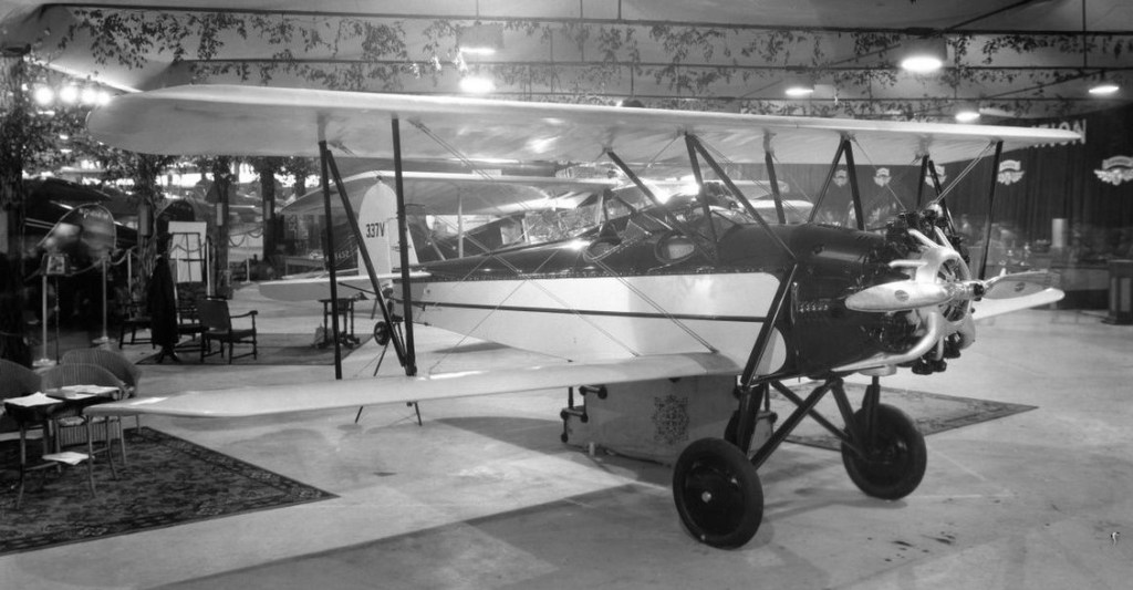
A Challenger powered-Command-Aire 5C3 was entered into the Guggenheim Safe Aircraft Competition in 1929. The 3C3 was the last aircraft not specially designed for the contest to be eliminated, and would actually enter revenue service. It later succeeded on a repeat of the test that it was eliminated on.
The Command-Aire 5C3 was featured in the Berryloid advertising series for aircraft dope, each featuring a different fabric covered aircraft, and each aircraft painted as a different bird. This advert was from the November 1929 Aerodigest
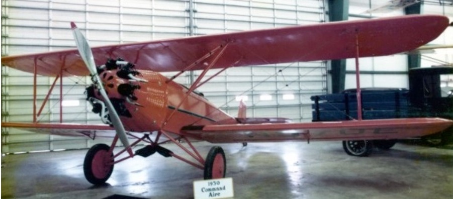
5C3 NC925E
In 1929, Command-Aire contracted the Curtiss Flying Service to handle sales, through their large number of facilities, and Curtiss purchased a large number of aircraft for flight training for their own schools. Recognizing that the excessive number of aircraft companies in the aviation industry would force consolidation into a smaller number of larger companies, it had long been the intention to merge Command-Aire into a larger company even before the onset of the Great Depression forced matters. Negotiations had been underway for just such a merger – into Curtiss, at one time the largest aircraft manufacturer in the United States, however while negotiations were still underway, Curtiss’s financial problems forced it to merge with Wright Aeronautical. Unfortunately, Wright had themselves recently absorbed Travel Air, whose offerings included the Travel Air 2000 which was similar to the Command-Aire biplanes. Negotiations collapsed, and along with them, went the contracts for supplying the flying schools – and access to the sales network.
Command-Aire landed a by now much needed contract from the Chilean government to produce 36 3C3-BTs to be built at a specially-built facility in Chile, however no Command-Aires seem to have been either used in that country, either civil or military.
Only one example appears to have been exported, a 3C3 that went to Canada in 1931, where it went through a succession of private owners as CF-APQ, having previously been NC5590 in the US.
Produced 1928-1931a total of 184-254 (total for 3C3, 4C3, 5C3, BS-14 and BS-16) were built/
1928 ATC 53, 2-201 Engine: 90 hp (67 kW) Curtiss OX-5 Propeller: 2-bladed Wooden fixed pitch Upper wingspan: 31 ft 6 in (9.60 m) Upper chord: 60 in (1.5 m) Wing sweep: 0° Lower wingspan: 31 ft 6 in (9.60 m) Lower chord: 60 in (1.5 m) Wing area: 303 sq ft (28.1 m2) Airfoil: Aeromarine 2A Length: 24 ft 6 in (7.47 m) Height: 8 ft 4 in (2.54 m) Empty weight: 1,410 lb (640 kg) Gross weight: 2,200 lb (998 kg) Useful load: 790 lb (360 kg) Fuel capacity: 40 US gal (150 l; 33 imp gal) Oil capacity: 4 US gal (15 l; 3.3 imp gal) Maximum speed: 100 mph (160 km/h, 87 kn) Cruise speed: 85 mph (137 km/h, 74 kn) Minimum control speed: 36 mph (58 km/h, 31 kn) Range: 440 mi (710 km, 380 nmi) 116 built. Crew: One Capacity: Two Undercarriage track: 87 in (2.2 m)
3C3-A 1929 ATC 118 Engine: 110 hp (82 kW) Warner Scarab 20 built. 1 fitted with Edo floats.
3C3-AT
3C3-AT N970E W-108
1929 ATC 151 2 seat trainer developed from 3C3-A about 6 built.
3C3-B 1929 ATC 120, 2-440 Engine: 105 hp (78 kW) Siemens-Halske Sh 12 5 built 1st possibly modified from 3C3 with a new c/n.
3C3-BT 1929 ATC 209 Engine: 113 hp (84 kW) Siemens-Halske Sh 14 2 seat trainer developed from 3C3-B. 2 built plus 1 converted from 3C3-B.
Command-Aire started in 1926 as the Arkansas Aircraft Co. Inc. of Little Rock, Arkansas.
In 1929 Command-Aire was one of the top manufacturers and was recognized for having one of only two designs to pass the Guggenheim Safety Trial, in which all existing aircraft designs were flown and judged for safety.
In 1930 the company entered their “Little Rocket,” in the All American Derby.
Command-Aire despite all of its successes was unable to survive the post-depression era and closed their doors forever in 1931.
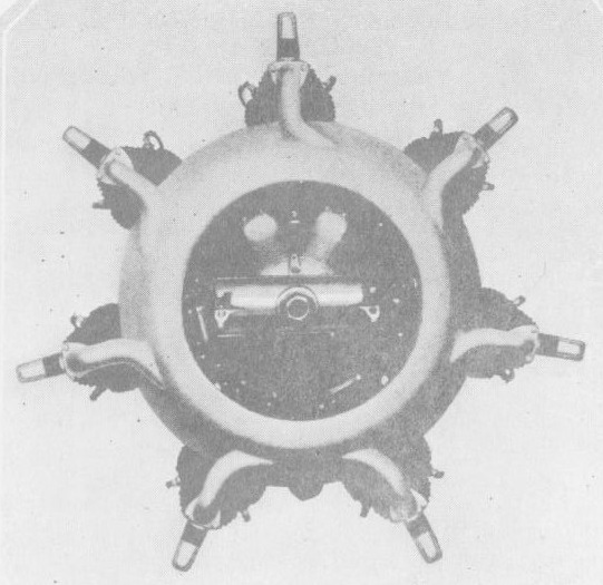
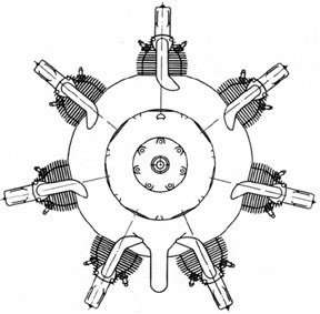
The Comet 7-D feature valves placed fore and aft, with exhaust valve forward for better cooling. Each cylinder has one rocker arm, ball bearing mounted, operating both valves on each cylinder. There is only one pushrod per cylinder. A single cam provides positive operation in both directions – push and pull – for all valve rods. The intake valves are operated by a downward pull on the valve rod. As a result, the tappet clearances on the intake valves decrease as the cylinders warm up, giving a longer intake opening at the higher speeds. The system reduces valve spring tension materially, giving a very light and evenly distributed load on the entire valve mechanism.
Spark plugs are placed on the sides of the cylinder heads for uniform spark plug temperatures. The cylinders are a steel barrel with integral mounting flange, over which a cast aluminium (Y-alloy) head is screwed and shrunk. The crankshaft is carried in roller bearings, and is of two pieces for use of a solid master rod.
The crankcase is built of two sections united by seven through bolts, as well as by the cylinder flanges. The gear case cover carries the magneto and tachometer gears and oil pumps. The diffuser cover supports the magnetos and carburettor. A ball thrust bearing is carried in the front section. The cam is ball bearing mounted.
Equipment included an air cleaner and heater, complete exhaust manifold, nose cowling, tool kit, and instruction book. Available at extra cost was a Heywood starter.
7-D Type: 7 cylinder, air cooled, fixed radial. Approval type certificate No.9 Military Rating: 130 hp at 1825 rpm Commercial Rating: 165 hp at 1900 rpm Displacement: 611 cu.in Compression ratio: 5-1 Bore: 4.5 in Stroke: 5.5 in Diameter: 46 7/8 in Length: 35 5/8 in Weight: 395 lb Fuel consumption: not more than .55 lb/hp/hr Oil consumption: not more than .015 lb/hp/hr Lubrication: Force feed, scavengers and pressure pumps Ignition: Dual Scintella magnetos Carburation: Stromberg Spark plugs: 2 per cylinder AC Price: $2700