A biplane (11 built) slightly larger than the F.1, with a Mercedes DIV engine, and armed with a Parabellum machine gun.
Era
Flugzeugwerft Lübeck-Travemünde F.1
A two-seat reconnaissance aircraft, powered by a Mercedes D III engine, three of which were built.
Flugzeugwerft Lübeck-Travemünde Gmbh
Founded in May 1914 at Travemunde Privall to specialize in seaplane design and construction, subsidiary of DFW. Aircraft included F.1, a two-seat reconnaissance aircraft, powered by a Mercedes D III engine, three of which were built. The F.2 biplane (11 built) was slightly larger, with a Mercedes DIV engine, and armed with a Parabellum machine gun. A total of 34 armed reconnaissance patrol biplanes with Benz IV engines was built 1917-1918.
Flug Werk FW 190

Altogether 20 kits were manufactured, 16 sold to customers. Among them are three kits are as static FW 190 in museums.
The flight work crew assembled FW 190 A8/N (D-FWJS), including all corrections and rework of different systems, for a German customer. The oil cooling system received an additional “ring oil cooler. Combustion air of the Ash 82T is sucked in vertical, behind the engine. To give the copied FW 190 as authentic an appearance as possible a rework became necessary, with the help of the additional oil cooler.
Further substantial changes concerned the brake linings as well as a variation in type of the brake pumps, which are installed at the pedals.
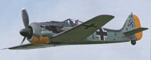
The first flight of the D-FWJS was accomplished by test pilot Klaus Plasa.
The flight testing of D-FWJS and D-FWWC without the use of the flap system for takeoff and landing were accomplished. However the flaps were used in the flight, and a “Lastigkeitsänderung” is clearly noticeable around the transverse axis, which could be well trimmed. The FW 190 test flight report written by Professor Kurt Tank, says when driving flaps and undercarriage “Lastigkeitsänderungen” were not produced.
In the FW 190 flight work uses in the house developed fin adjustment devices, similarly those for the use in the ME 262 developed trim actuators. Original devices available, but such systems, e.g. original undercarriage introduction engines and Cyclo transmissions were not used for safety safety reasons. The production of the 40’s was shaped by scarcity of raw materials, a large number of these electrical trim engines did not have ball bearings, but only steel sockets, as “emergency substitute solution “. The original drives for the landing flaps this, which was not acceptable for safe flying operation now.
Flight testing of the first FW 190A-8/N began in July 2004, and was to continue in 2007 with test pilot Horst Philipp at the controls.
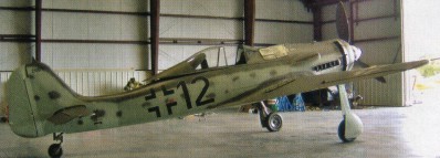
At Gammelsdorf in Upper Bavaria, the Flug Werk company unveiled its first long-nose FW 190D-9/N “Dora”.
Substituting for the original Jurno 213A engine is an Allison V-1710 engine, specially modified by Bud Wheeler’s Pen nsylvania- based ACE Competition engines. The Allison unit is 500kg (1,1001b) lighter than the Jurno, so to compensate a specially constructed engine mounting has been manufactured from chrome-molybdenum steel. Wheeler has also extensively modified the reduction gear in order to achieve the same propeller speed as the FW 190A-8, so it will be possible to use the same blades as fitted to the radialengined version.
Specially manufactured exhaust pipes will ensure that this area of the 190D will look authentic from the outside.
Three FW 190D-9s will be built, with the first example going to a Florida-based owner once it is completed. The second aircraft is also due to be exported, but the third 190D will be retained by Flug Werk, together with one of the 1 90A-8s, and be used for display and film work.
The first of the Flug Werk FW 190D-9/N Doras was handed over to its owner Tom Blair at Kissimmee, Florida, 11 December 2007.
Flug Werk AP-51 Palomino
The AP-51 Palomino structural kit from FlugWerk, named “Palomino” in order to document it’s closeness to the P-51 Mustang, yet make it clearly discernable from the real P-51’s, so the new components do not end up on type certified Mustangs. This is a requirement by the FAA.
All of the AP-51 assemblies are manufactured from western materials, such as SAE 2024 and/or SAE 7075 aluminum alloys and SAE 4130 steel alloy, where called for, in high strength applications. The structures are built, following the standards of the original NAA manufacturing drawings and standards. Utilizing CNC-machinery FlugWerk manufacture all brackets, hinges for the tail-gear, all flying surfaces and the landing gear trunnion boxes: All of these new components are better in quality and strength than their sand-casted predecessors from wartime. The trunnion boxes are made using a 5-axis CNC mill.
The AP-51 wing profile demands absolute true coordinates, and the jigs which are utilized during the assembly processes are built following today’s aerospace industry standard. Each individual jig employs fold-down templates to assure correct profile conforming surfaces to the smallest fraction of an inch while the entire assembly is under construction. Before the jigs are used for any assembly wrok they are heat treated for the purpose of relieving any stresses that have built up during their welding assembly. The entire jigs are therefore put in a furnace for a given time. After heat-treating the jig’s structures, all critical surfaces are milled to their final dimensions and by that gain the purpose as measuring zero-coordinates. Even the assembly work is done in a climate-controlled environment.
The stamped and trued ribs are subject to corrosion proofing, employing the “Alodyne” process, followed by primer coating with two part Epoxy paint prior to assembly.
The final result is an airframe that is similar and in some regards better to the original structures.
The AP-51 Palomino airframe kit includes:
- Engine mount, with smile but w/o lord mounts
- Center fuselage with dog-house, inlet- outlet duct, windshield assembly and firewall with stamped, dished insert. P-51 D style.
- Aft fuselage
- Vertical stabilizer, with ventral fairing
- Rudder ( for fabric covering ) with trim tab and balance weight
- Horizontal stabilizer ( standard incidence is set for P-51 D )
- Elevators ( for fabric covering ) with trim tab and balance weight, or
- Elevators ( metal skinned ) with trim tab and balance weight
- Wing, with left and right tip-extensions, body fairings, clamshell- and spade doors
- Ailerons, left and right
- Flaps, left and right
All structures are built using brand new ALCOA/USA supplied aluminum extrusions and AN/MS hardware, also imported from the US.
The 2010 price for the airframe kit in US $: 475.000 ex works” Gammelsdorf/Germany.
Flug Werk GmbH
2003: Based in Ascoli Piceno, Italy.
Jerry Yagen’s Flug Werk.
2010: FLUG WERK GmbH, Kothingried 4, 85408 Gammelsdorf, Germany.
In addition, Flug Werk was recognized for two years as subcontracting firm for the EADS and different components for the ME 262 reproduction of the Messerschmittstiftung manufacture. Among them is also new, “fin adjustment equipment specified in the RLM jargon “(= horizontal stabilizer trim). It is a quite complex construction unit, on which the working reliability of the entire aircraft hangs. A homogenous retrofit of the others “Swallows “of the American 262-Herstellers is available.
Flug Werk founder Claus Coiling says that the demand for the new-build FW 190s means that the original planned production of 12 airframes has been increased to 20 examples. After production of FW 190 parts has finished, the company will proceed with the manufacture of a North American P-51 Mustang Iookalike” airframe kit called the AP-51 Palomino.
2010: The workshop of Achim and Elmar Meiser at Bremgarten airfield, Germany, Flug Werke.
Flugtechnische Fachgruppe FS.17
To practically test the position of the pilot, the Flugtechnische Fachgruppe (Aero-technical Group) Stuttgart constructed the FS17 research aircraft. The FS17 was a glider that was designed to withstand forces up to 14g. After the completion of the test program an order was given by the DVL ((Deutsche Versuchanstalt für Luftfahrt e.V. Berlin-Aldershof) (German Experimental Department for Aerospace Reg.) to the FFG Berlin ((Flugtechnische Fachgruppe)(Aero-technical Group)) to construct a powered aircraft. FFG Berlin was chosen as it possessed the necessary workshops and technicians. In the Spring of 1943 the FFG Berlin constructed the Berlin B9 to the specifications provided.
F&FW Diamant / Swiss Federal Institute of Technology Ka-Bi-Vo / HBV Diamant
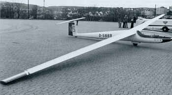
The ideal of an all-glassfibre sailplane was achieved in several stages, the first being development of the fuselage and tail unit designed by Thomas Bircher and J von Voornveld at the Swiss Federal Institute of Technology in Zurich under the direction of Professor Rauscher. A prototype fuselage was built in 1962 and was flown with the plywood and fabric wings of a Schleicher Ka 6CR, the resulting aircraft being designated Ka-Bi-Vo.
The Diamant’s development was now gradually taken over by Plug- und Fahrzeugwerke AG FFA, and the next stage was the HBV-Diamant 15 which used the 15m span Hutter H-30TS wings of the Glasflugel H 301 Libelle. This first flew on 5 September 1964 and 13 of this variant were subsequently built; the Libelle’s wings being glassfibre balsa sandwich shells without ribs, featuring ailerons that gave partial downward movement when the flaps were lowered, and there were glassfibre dive brakes forward of the flaps.
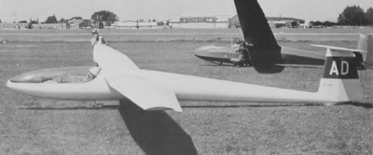
The HBV-Diamant 15 was followed by the generally similar Diamant 16.5, with wings of increased span (16.5m) designed and built by FFA; a total of 41 of this variant were built. This was the first all glass fiber production sailplane, not using balsa or other wood sandwiched between the fiberglass layers.

The Diamant 18 is an 18 m development of the 16.5, first flying in February 1968, with extended inboard wing and flap sections and a new wingtip cap. like the Diamant 16.5, water ballast an be carried in the wing roots. The monocoque fuselage is an epoxy-glassfibre sandwich with foam inserts, and the tail unit is of the same construction, the allmoving one-piece tailplane being mounted on top of the fin. As well as a small tailwheel (a tailskid is optional) there is a manually-retractable monowheel with a brake, and another feature is a glassfibre ring spring shock absorber; the tow release retracts with the landing gear. The pilot sits in a semi-reclining position under a long forward sliding one-piece canopy, and there is provision for radio and oxygen.

At least one Diamant 18 was substantially modified by Dan Pierson of Los Angeles, CA to have a 19.0 m / 62.3 ft wing carrying 145 kg / 320 lb of water ballast bringing the gross weight up to 673 kg/ 1,480 lb.
The HBV Diamant and Diamant 16.5 are ATC, while the Diamant 18 is EXP.
A powered version of the Diamant 18 known as the EFF Prometheus 1 made its first flight on 21 June 1971, powered by a 176lb st Microturbo Eclair II turbojet mounted behind the cockpit. The Prometheus was developed by EFF – Entwicklungsgemeinschaft fur Flugzeugbau der Akademischen Fluggruppe, and it was later converted back to a standard Diamant 18.
Variant:
EEF Prometheus 1
Diamant 16.5M
Wing span: 16.5m / 54.2ft
Wing area: 12.2sq.m / 143sq.ft
Empty Weight: 270kg / 595lb
Payload: 138kg / 305lb
Gross Weight: 408kg / 900lb
Wing Load: 30.91kg/sq.m / 6.29lb/sq.ft
Water Ballast: 0
No. of Seats: 1
No. Built: 43
L/DMax: 42 100 kph / 54 kt / 62 mph
MinSink: 0.55 m/s / 1.80 fps / 1.0 kt
Aspect ratio: 20.5
Airfoil: Wortmann FX-62-Z-153
Diamant 18
Wing span: 18.0 m / 59 ft 0 in
Wing area: 14.28 sq.m / 153 sq.ft
Airfoil: Wotmann FX-62-Z-153 mod.
Length: 7.72 m / 25 ft 4 in
Height: 1.35 m / 4 ft 5 in
Empty Weight: 280 kg / 617 lb
Payload: 160 kg / 353 lb
Gross Weight: 440 kg / 970 lb
Water ballast: None
Wing Load: 30.8 kg/sq.m / 6.34 lb/sq.ft
Max speed: 149 mph / 129 kt / 240 km/h
Max rough air speed: 108 kt / 200 km/h
Stalling speed: 32.5 kt / 60 km/h
MinSink: 0.52 m/s / 1.71 fps / 1.01 kt at 45 mph / 39 kt / 72 km/h
L/DMax: 45 at 100 kph /54 kt / 62 mph
Aspect ratio: 22.7
No. of Seats: 1

Floyd Para-Cycle
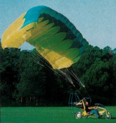
Designed by Orville Lee Floyd III, the Para-Cycle flies as a powered parachute, using a 400 sq.ft rectangular chute from Performance Design Inc, powered by a 40 hp two stroke engine. It pedals on the ground as a three wheel, twenty-one speed tricycle, and drives at up to 15 mph powered by an optional electric hub motor and rechargeable 24 volt battery.
The prototype was shown at Oshkosh 1997. On the prototype the pedals are loosened from the bicycle crank and become the parachute foot controls.
Robert Baslee of Airdrome Airplanes has teamed with Lee to provide engineering and manufacturing support. The power cage has progressed through several changes.
Bike type steering on the ground is conventional with a long-throw handle bar that supports the engine throttle in the left hand and wheel brake and electronic speed control for the optional ground mode electric propulsion in the right hand.
The right and left red lines, attached to the disconnected foot pedals on the preproduction prototype, pulls the canopy’s leading edge corners, which controls turns.
Changes to be incorporated in the production models included widening the gear track from 47 in to 57 in, lowering the engine 4 in for better ground stability, increasing the airframe tube diameter from 1.25 in to 1.5 in, changing the prop cage from six sided to round. A front hydraulic brake will be optional, the front end length will be customised to the customer, and a larger 452 sq.ft chute will allow up to 250 lb payload.
Alternatives to the standard 40 hp 2si 460F-40 engine will be the 50 hp 2si, Rotax 447, and Rotax 503.
Florov 4302

By 1944 Dushkin, who was working on the NII-1 of the NKAP, created a new version of the RD-2MZV reactive engine. This new power plant used a fuel pumping system, consisting of kerosene and nitric acid. Its main feature was the presence of two chambers, a large 1,100 kg thrust and a small 300 kg.
This allowed taking off and reaching the maximum height with the two chambers and then using the force of the small one in horizontal flight. This was able to save fuel and achieve a considerable increase in engine operating time.
Initially it decided to install this engine in the interceptor “Malyutka” of NN Polikarpov, which was projected in 1944, but his sudden death did not allow the builder to finish the job.
During state tests of the RD-2MZV, developed in May 1945, a joint thrust force of 1500 kg was achieved at take-off, 1250 kg as normal thrust and 500 kg as minimum thrust. Working only the small chamber, a thrust of 300 kg was achieved and the minimum thrust was 100 kg. The weight of the engine with all its aggregates reached 224 kg. The production of 30 power sets was approved with the delivery of the first on March 10 and the last on August 10, 1946.
Factory No. 165 was selected as the engine manufacturer, which was to work closely with other plants. Assembly and control tests were entrusted to the NII-1.
At that time, the experimental aircraft with a liquid reactive engine designed by IF Florov was already being built in the NII-1. This aircraft had begun to be projected two years ago, when by GOKO resolution No. 5201 issued on February 18, 1944, the Reactive Technique Institute (NII-1), transferred to the NKAP, was given the task of dedicating itself to the development of reactive engines. The leadership of the NII-1 was assigned to the head of the NII VVS PI Fiodorov and as his replacement was appointed VF Boljovitinov.
The new managers of the NII-1 enjoyed aeronautical construction. For this reason, in parallel to the main tasks of the institute, linked to the creation of reactive engines by the Isayev and Dushkin collectives and turbojets by AM Lyulka, it was decided to build an experimental aircraft from a project developed by Boljovitinov and Florov. This task was approved by the 18 Principal Directorate of NKAP, responsible for the reactive technique.
It was proposed to build two variants of the aircraft: one with an Isayev powerplant, which was named “4302” and another with the Dushkin engine, which was named 4303.
According to the project, the “4302” should have a flying weight of 2320 kg. The maximum speed at sea level had to reach 1010 km / h (M = 0.82), 1015 km / h (М = 0.88) at 5000 meters and 1050 km / h (М = 0.99) at 15000 meters. The ascent time at 15,000 meters was calculated at 2 minutes 22 seconds and the practical ceiling at 18,850 meters. The expected flight time was 46 minutes.
Both projects were conceived to test the powerplant itself, as well as the aerodynamic characteristics of flying at high speeds. Another primary objective was the study of the pressure distribution laws by the wing profile and the calculation of overloads in flight, especially in turbulence generation areas.
It was planned to build a total of six copies of which the first two would be used for the preparation of the flight personnel and the rest for the development of the experiments.
The institute’s productive capacities were scarce, so the construction was contracted to Factory No.21 named in honor of Sergo Ordzhonikidze and located in Gorky city.
Working drawings were ready on 1 January 1946 and once delivered the factory started production. The first two were ready for delivery in March.
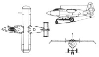
The “4302” was designed as an experimental all-metal monoplane. The wing design was straight, with a constant section throughout the span. In order to improve directional stability and reduce the effect of turbulence at high speeds, the wingtips were angled 45º downwards. The wing profile used was the TsAGI 13145 with laminar flow and thickness of 13%.

The fuselage, also metallic, had a cigar shape with a circular cross section, with a diameter of 1,150 mm at its widest part. At the bottom of the nose was the towing hook.
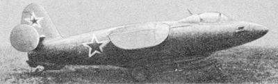
The tail unit was cantilever type and terminated in vertical washer-like surfaces. The empennage was constructively integrated into the fuselage. All the coating, including the rudders and ailerons, was metallic.
The landing gear was one of the most complex elements. For the first flights a fixed gear with three wheels obtained from a Lavochkin La-5 was used. Later, the “4302” was equipped with a retractable ski for landing and took off using an ejectable forklift. The landing ski was constructed of stainless steel and featured a hydraulic release system. In the middle portion of the ski profile were two grooves to fix the trolley, which was constructed of steel tubes.
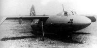
The main 650x200mm wheels featured disc brakes. The 400x150mm double wheel front unit had a hydraulic damper. To reduce the lift of the truck once it was separated from the plane, the braking system was activated automatically after release. When the truck was detached, the ski was retracted.
By this time the leadership of NKAP had changed (instead of AI Shajurin, MV Jrunichev had been appointed) and this structure became the Ministry of Aviation Industry (MAP). The new MAP managers had a negative reception towards the plane, considering that the NII-1 had “meddled” in a task that was not within its competence. For this reason, as of February 1946, all financing for this project was withdrawn.
The new director Ya. L. Bibikov and VF Boljovitinov wrote directly to Stalin, explaining that at 1 April of 1941 the first issue of flight he was at 70% completion and continue the work the prototype would be ready for state tests for the month of July.
The vice-president of the Council of Ministers of the USSR, NA Bosniecienski, who after Malenkov’s departure, attended the aviation, ordered Khrunichev and Vershinin to seek a solution to the dilemma. Reluctantly, Khrunichev was forced to give in.
The new VVS chief, Marshal Vershinin reacted differently. On the one hand, he appreciated scientific work, especially in the field of military aviation, but on the other hand he was offended, since the experimental production plan was approved by the NKAP during the period of his taking office, he decided to support the NII-1.
Together with the new VVS chief engineer, IV Markov issued a communication in which he recognized the great value that an interceptor with these features would have for the VVS and requested that state tests be carried out in 1946.
In response, Khrunichev replied that the data presented by the NII-1 should be subject to a review and created a ministerial commission to do so.
The commission was chaired by Professor IV Ostoslavski and included the main builder of OKB-155, AI Mikoyan, the head of department of TsAGI VN Matvieyev, the group head of the 7th MAP Directorate, IV Loktiev and the head of the (Directorate of the MAP, VV Yakolievsky The result of the commission, presented in June 1946, yielded the following results:
“… the maximum speed of the plane will be between 900 and 950 km / h instead of 1000 – 1100 km / h and the ceiling will be limited to 12000 – 13000 meters instead of 20 000 m, due to the absence in the airplane from a sealed cabin. The duration of the flight presented in the letter is 46 minutes. The commission considers that the maximum flight autonomy will be 5 minutes. “
The commission’s results were based on the results obtained with the straight-wing Bisnovat 5, which had been unable to obtain the proposed speed. Florov replied that his aircraft had been designed with the latest strength requirements in mind and with the correct wing selection recommended by TsAGI.
Despite the commission’s report the MAP was instructed to finish and test the experimental specimen “4302”.
In response to the MAP meeting in September 1946, Khrunichev severely criticized the NII-1 leadership and demanded to reorganize the institute’s activity on a purely scientific and not practical profile. The minister ordered to separate the group of builders from the institute and give them a constructive base to continue their activity.
As the new director of the NII-1, MV Keldysh was appointed and in its new structure were three collectives: OKB-1 from LS Dushkin, OKB-2 from AM Isayev and OKB-3 from MM Bondaryuk and a department of gunpowder accelerators.
Jrunichev decision of the bureau of buildings Florov was renovated. The personnel and the productive base were placed under the direction of Bisnovat. Under these conditions, NII-1 survived one more year, until in 1948 it was absorbed by TsIAM. The Dushkin and Bondaryuk groups passed to this institute. Isayev’s group would go to NII-8 of the Ministry of Armaments, dedicating itself to the construction of reactive rocket engines.
By the fall of 1946 one in glider configuration without an engine) was ready for testing and was sent to the LII. Another Isayev-powered example was in the completion phase. Under pressure from the military, the MAP was forced to continue the construction of this copy to deliver it to the LII. With so much pressure, the works on the “4302” could not be carried out to the expected magnitude. It is stated that three examples were completed.

The flights were started in 1947. In total, 20 flights were executed, of which 19 were carried out in the version without an engine. The Isayev jet engine flight was executed by test pilot AK Pajomov in August. This flight started smoothly, but towards the end of the engine work pieces were damaged and nitric acid fumes filled the cabin.
Pajomov managed to land the plane. After this flight, the jet engine aircraft development program was closed. By then, significant progress had been made in the development of turbojet engines capable of high thrust.
After this Ilya Florov went on to dedicate himself to scientific activity, defended his candidacy thesis and later his doctorate, going on to direct a scientific group. He would never design airplanes again.
4302
Powerplant: A 1,100 kg thrust AM Isayev liquid reactive engine
Wingspan: 6,932 m
Wing area: 2 m²
Length: 7.152 m
Height: 3.06 m
Maximum takeoff weight: 2398 kg
Maximum speed achieved: 520 km / h
Calculated top speed: 950 km / h
Accommodation: 1