Junkers Jumo 205 / Jumo 207

Jumo 205

The Junkers Jumo 205 aircraft engine was the most famous of a series of Diesel engines that were the first, and for more than half a century the only, successful aircraft Diesel engines. The Jumo 204 first entered service in 1932. Later engines in the series were styled Jumo 206, Jumo 207 and Jumo 208, and differed in stroke and bore and supercharging arrangements. In all more than 900 of these engines were produced.

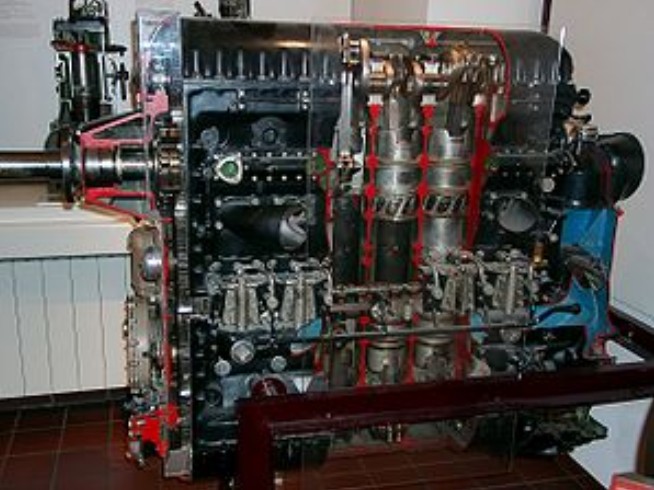
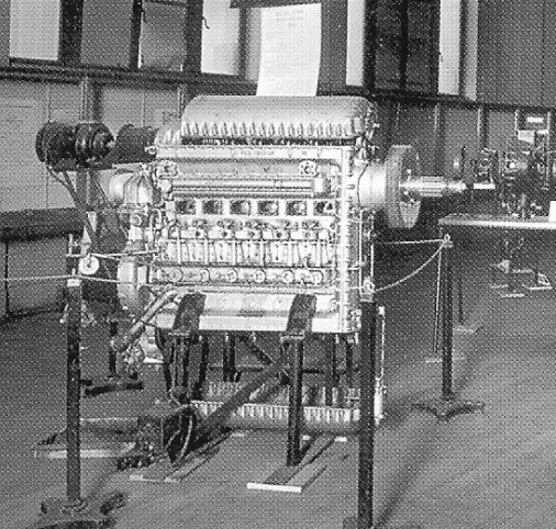
These engines all used a two-stroke cycle with twelve pistons sharing six cylinders, piston-head to piston-head in an opposed piston configuration. This unusual configuration required two crankshafts, one at the bottom of the cylinder block and the other at the top, geared together. The pistons moved towards each other during the operating cycle. Intake and exhaust manifolds were duplicated on both sides of the block. There were two cam-operated injection pumps per cylinder, each feeding two nozzles, for 4 nozzles per cylinder in all.

As is typical of two-stroke designs, the Jumos used fixed intake and exhaust ports instead of valves, which were uncovered when the pistons reached a certain point in their stroke. Normally such designs have poor volumetric efficiency because both ports open and close at the same time and are generally located across from each other in the cylinder. This leads to poor scavenging of the burnt charge, which is why valve-less two-strokes generally produce smoke and are inefficient.

The Jumo solved this problem to a very large degree through clever arrangement of the ports. The intake port was located under the “lower” piston, while the exhaust port was under the “upper”. The lower crankshaft ran eleven degrees behind the upper, meaning that the exhaust ports opened and, even more importantly, closed first, allowing proper scavenging. This system made the two-stroke Jumos run as cleanly and almost as efficiently as four-stroke engines using valves, but with considerably less complexity.

There is some downside to this system as well. For one, since matching pistons were not closing at quite the same time, but one ran “ahead” of the other, the engine could not run as smoothly as a true opposed style engine. In addition, the power from the two opposing crankshafts had to be geared together, adding weight and complexity, a problem the design shared with H block engines.

In the Jumo, these problems were avoided to some degree by taking power primarily from the “upper” shaft. All of the accessories, such as fuel pumps, injectors and the scavenging compressor, were run from the lower shaft, meaning over half of its power was already used up. What was left over was then geared to the upper shaft, which ran the propellers. In all, about three-quarters of the power to the propellers came from the upper crankshaft.

In theory, the flat layout of the engine could have allowed it to be installed inside the thick wings of larger aircraft, such as airliners and bombers. Details of the oil scavenging system suggest this was not possible and the engine had to be run “vertically”, as it was on all designs using it.

A twelve cylinder version, the Jumo 218, was designed but never built, while a single 24-cylinder 4-crankshaft Junkers Jumo 223 was built and tested.

The Jumo 204 and 205 were licensed to Napier & Son, who built a small number as the Napier Culverin just prior to the war. After the war, they mounted three Culverins in a triangle layout to produce the Napier Deltic, which was for some time one of the most powerful and compact diesel engines in the world. Work on this engine started in 1947 and engines were running by 1950.
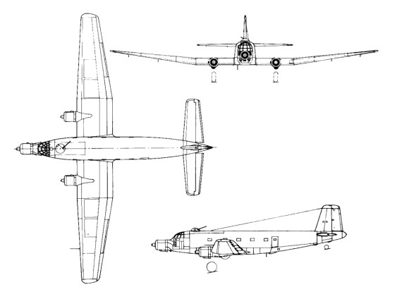
The Jumo 205 powered early versions of the Junkers Ju 86 bomber, but was found too unresponsive for combat and liable to failure at maximum power, common for combat aircraft. Later versions of the design also used the engine for extreme high-altitude use. It was far more successful as a power unit for airships, for which its characteristics were ideal, and for non-combat applications such as the Blohm & Voss Ha 139 airliner.

Applications:
Blohm & Voss BV 138
Blohm & Voss Ha 139
Blohm & Voss BV 222
Dornier Do 18
Dornier Do 26
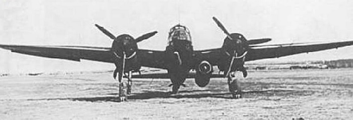
Junkers Ju 86

Specifications:
Jumo 205 A
Type: Six-cylinder 12-piston liquid-cooled opposed piston inline two-stroke diesel engine
Bore: 105 mm (4.13 in)
Stroke: 160 mm (6.3 in)
Displacement: 16.63 L (1,015 in³)
Length: 76.5 in (1,934 mm)
Width: 21.54 in (547 mm)
Height: 52.17 in (1,325 mm)
Dry weight: 595 kg (1,312 lb)
Fuel system: Fuel injection
Fuel type: Diesel
Oil system: Forced with one pressure and two scavenge pumps
Cooling system: Liquid-cooled
Power output: 647 kW (867 hp) at 2,800 rpm
Specific power: 39.0 kW/L (0.86 hp/in³)
Compression ratio: 17:1
Power-to-weight ratio: 1.09 kW/kg (0.66 hp/lb)
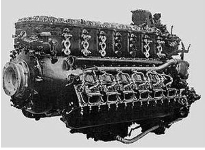
Junkers Jumo 204 / Fo4 / SL1 / Jumo 4 / Napier Culverin

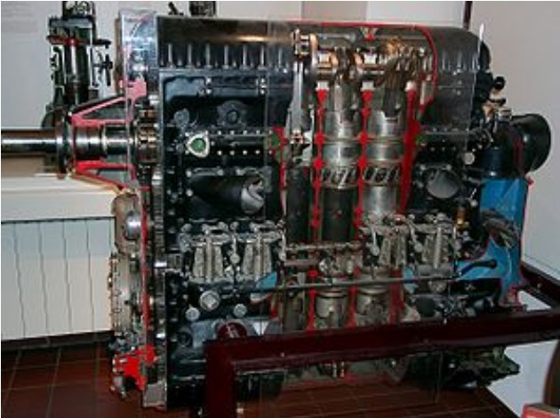
Cut away view of a Jumo 205, a decreased capacity version of the Jumo 204

Development of the Junkers diesel engines started in the 1920s with the Junkers Fo3 and Junkers Fo4/Junkers SL1. The Fo4 was re-designated Junkers 4, which in turn was re-designated Junkers 204 by the Reichsluftfahrtministerium (RLM).

These engines all used a two-stroke cycle with six cylinders and twelve pistons, in an opposed piston configuration with two crankshafts, one at the bottom of the cylinder block and the other at the top, geared together. The pistons moved towards each other during the operating cycle. Intake and exhaust ports were duplicated at both ends of the block. There were two cam-operated injection pumps per cylinder, each feeding two nozzles, totaling four nozzles per cylinder.

As is typical of two-stroke designs, the Jumos used fixed intake and exhaust ports instead of valves, which were uncovered when the pistons reached a certain point in their stroke. Normally such designs have poor volumetric efficiency because both ports open and close at the same time and are generally located across from each other in the cylinder. This leads to poor scavenging of the burnt charge, which is why valve-less two-strokes generally run smoky and are inefficient.

The Jumo 204 solved this problem to a very large degree through a better arrangement of the ports. The intake port was located under the “lower” piston, while the exhaust port was under the “upper”. The lower crankshaft ran eleven degrees behind the upper, meaning that the exhaust ports opened first, allowing proper scavenging. This system made the two-stroke Jumos run as cleanly and almost as efficiently as four-stroke engines using valves, but with considerably less complexity.

The Jumo 204 (originally designated Jumo 4) was test flown in early 1929 installed in a Junkers G 24. The Jumo 204 first entered service in 1932.

Later engines in the series were designated Jumo 205, Jumo 206, Jumo 207 and Jumo 208, they differed in stroke and bore and supercharging arrangements.

The Jumo Fo3 and 204 were licensed to Napier & Son, who built a small number as the Napier Culverin just prior to the war. Late in the war, they mounted three Culverins in a triangle layout to produce the Napier Deltic, which was for some time one of the most powerful and compact diesel engines in the world.

First run in 1934, the Culverin name is derived from the French word, culverin, for an early cannon or musket. First flown in 1938 using a Blackburn Iris V biplane flying-boat aircraft, the engine went into production for use in the Fairey III biplane.

Variants:
Mo3
A research diesel engine for test bed use only, the Mo3 was a four cylinder, (eight piston), opposed-piston engine designed to run horizontally. Tested from 1913, the problems found in testing the Mo3 were progressively solved after WWI with the Fo3 and later opposed piston diesels.

Fo3
From 1924, Junkers experimented with the Fo3, A vertical 5-cyl. opposed-piston diesel, which ran on a test bed in the summer of 1926, developing 620 kW (830 hp) at 1,200 rpm. Mostly successful, the Fo3 did highlight the need for accurate dynamic balancing of the rotating components.

Fo4
(a.k.a. SL1) The Fo4, benefiting from the experience gained with the Fo3, was a six-cylinder opposed-piston diesel engine, tested from 1928 and flown in the nose of a Junkers G.24 from 30 August 1929.

Jumo 4
After the successful bench runs and flight tests, the Fo4 was refined into the certicated Jumo 4, enjoying limited success powering re-engined Junkers F24kay airliners of Deutsche Luft Hansa, remaining in service until 1939.

Jumo 204
Later production of refined Jumo 4s, designated Jumo 204 in three sub-variants: 204A, 204B,and 204C, differing in airscrew drive arrangements.

Napier Culverin
Licensed built version of the Junkers Jumo 204 six-cylinder vertically opposed liquid-cooled diesel aircraft engine built by Napier & Son.

Applications:
Junkers F.24kay
Junkers Ju 52
Junkers Ju 86
Junkers G.38
Blohm & Voss BV 138
Blackburn Iris V
Fairey III

Specifications:
Jumo 204
Type: Six-cylinder 12-piston liquid-cooled opposed piston inline two-stroke diesel engine
Bore: 120 mm (4.72 in)
Stroke: 210 mm (8.27 in)
Displacement: 28.5 l (1,739 in³)
Length: 1,260 mm (49.61 in)
Width: 510 mm (20.08 in)
Height: 1,510 mm (59.45 in)
Dry weight: 750 kg (1,653 lb)
Power output: 552 kW (740 hp) at 1,800 rpm
Specific power: 19.3 kW/l (0.42 hp/in³)
Compression ratio: 17:1
Specific fuel consumption: 212 g/(kW•h) (0.35 lb/(hp•h))
Power-to-weight ratio: 0.74 kW/kg (0.45 hp/lb)

Napier Culverin
Type: 12-piston 6-cylinder vertical opposed-piston liquid-cooled diesel engine.
Bore: 4.75 in (120.65 mm)
Stroke: 8.25 in (209.55 mm)
Displacement: 1,737 cu in (28.5 lt)
Dry weight: 1,785 lb (809.6 kg)
Valvetrain: Piston ported
Fuel system: Fuel injected
Fuel type: Diesel oil
Cooling system: Liquid cooled
Reduction gear: Spur geared, reduction ratio 0.6935:1, right hand tractor
Starting system: Compressed air starter
Power output: 821 hp at 2,050 rpm
Power-to-weight ratio: 0.46 hp/lb

Junkers Jumo 210 / L10

Jumo 210

Development of the V12 Jumo 210 itself started in 1931 under the designation L10. The L10 was Germany’s first truly modern engine design, featuring three valves per cylinder, an inverted-V layout, a supercharger as standard equipment, and a cast cylinder block. The 210 was odd in that the cylinders were machined into a block along with one side of the crankcase, two such parts being bolted together side-by-side to form the engine. Normal construction techniques used three parts, two cylinder blocks and a separate crankcase.

The L10 was first ran in static tests on October 22, 1932. With the official formation of the RLM in 1933, engine naming was rationalized with Junkers receiving the “200 block”, the L10 becoming the 210. Type approval was achieved in March 1934, and it first flew on July 5, 1934 installed in a Junkers W33. The design had initially aimed for 700 PS, but the prototypes delivered only about 600 PS, so there was some disappointment in the industry. Nevertheless almost all German aircraft designs of the era were based on the 210, which is why they were so small compared to other country’s efforts.

Initial production of the 610 PS (602 hp, 449 kW) Jumo 210A started in late 1934. Further development led in 1935 to the 640 PS (631 hp, 471 kW) 210B and 210C. Both added a new supercharger for improved performance, along with a dump valve to avoid overboost. The B model had its propeller geared at 1:1.55 (prop:engine rpm) for high-speed use, while the C model was geared at 1:1.63 for slower flying speeds. In 1936 the new 670 PS (661 hp, 493 kW) 210D and 210E were introduced, which had the same gearing as the B/C but used a new two-speed supercharger to increase takeoff power and altitude performance.

The Jumo 210G had a direct injection system developed by Dr. Lichte. The Jumo system used a small pump piston positioned beside each of the main cylinders, driven off the crank shaft. The injector used a simple check valve to prevent internal pressure from blowing back into the fuel line, and the pump was timed to inject at the proper point in the intake cycle. Inclusion of the injection system increased takeoff performance by about 20 PS without increasing boost rates and it also reduced fuel consumption. For those reasons most newer German engine types were set up with fuel injection systems. The Jumo 210G was rated at 700 PS (690 hp, 515 kW) and was only available for fast aircraft like the Bf 109 or Bf 110 but not for slow aircraft like the Ju 87.

Further developments were planned as Jumo 210F and 210H, but never built. In 1935 the Jumo 210H was used for development of the Jumo 211. A Jumo 210S was a special development by the DVL with special regulation mechanisms. Production of the Jumo 210 came to an end in about 1938.

Applications:
Arado Ar 68 – only in Ar 98E
Focke-Wulf Fw 159
Focke-Wulf Fw 187
Heinkel He 112
Junkers Ju 87 – only in Ju 87A
Messerschmitt Bf 109 – only in Bf 109 A-D
Messerschmitt Bf 110 – only in Bf 110 A/B
Messerschmitt Me 262 V1 – Only in first test flight, prototype’s BMW 003 axial-flow jet engines failed shortly after takeoff, aircraft brought around and back on the nose-mounted Jumo 210’s power alone.

Specifications:
Jumo 210
Type: Twelve-cylinder supercharged liquid-cooled inverted V aircraft engine
Bore: 124 mm (4.88 in)
Stroke: 136 mm (5.35 in)
Displacement: 19.7 l (1,202 in³)
Length: 1,478 mm (58.19 in)
Width: 686 mm (27.01 in)
Height: 960 mm (37.8 in)
Dry weight: 442 kg (974 lb)
Valvetrain: Overhead camshaft
Supercharger: Two-speed centrifugal type supercharger with automatic boost control
Fuel system: Carburetor
Fuel type: 87 octane rating gasoline
Cooling system: Liquid-cooled, ethylene glycol
Reduction gear: Spur, 1.75:1 or 1.59:1
Power output:
508 kW (690 PS or 681 hp) at 2,700 rpm for takeoff
515 kW (700 PS or 690 hp) at 2,700 rpm at 1,500 m (4,920 ft), first supercharger speed
501 kW (680 PS or 671 hp) at 2,700 rpm at 3,700 m (12,140 ft), second supercharger speed
Specific power: 26.14 kW/l (0.57 hp/in³)
Compression ratio: 6.5:1
Specific fuel consumption: 322-335 g/(kW•h) (0.53-0.55 lb/(hp•h))
Power-to-weight ratio: 1.17 kW/kg (0.71 hp/lb)

Junkers EF-127 Walli

Besides Bachem with the Ba-349 Natter, three other companies submitted proposals for the Jägernotprogramm (Emergency Fighter Program). The front runner was Ernst Heinkel A.G. with their P.1077 Julia which took off from a rail and landed on a skid like the Me-163, the runner up was the Junkers Flugzeug und Motorenwerke’s EF-127 Walli; the Messerschmitt A.G.’s P.1104 was also in the running. As expected, Heinkel won the contract.

Junkers Ju.488

Some sources claim that this was a development of the Ju 388, but it actually was a four-engined long-range bomber, built of Ju 188, Ju 288 and Ju 388 parts. The development of the Ju 488 was ordered from manufacturers in occupied France, who were not very motivated. When the prototype finally neared completion in 1944, it was destroyed by the French resistance with sten guns and grenades.

Junkers Ju.390

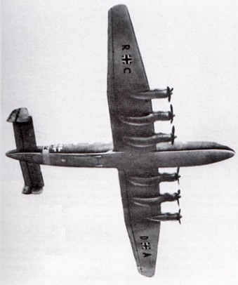
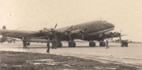
The German Junkers Ju 390 long range heavy bomber aircraft design was intended to be able to strike at locations along the east coast of the United States during World War 2. The Ju 390 itself was a further development of the Junkers Ju 290 and was also tasked to fulfill the roles of maritime reconnaissance and transport in addition to its bombing duties. The Ju 390 – also known under the unofficial name of “New York Bomber” – was developed as two working prototypes, effectively making the idea of transatlantic bombing theoretically possible for Hitler and his Luftwaffe. The Ju 390 was part of the failed “Amerika Bomber” project considered by the Germans, this including the Messerschmitt Me 264 and Focke-Wulf Ta 400 designs.

The Junkers Ju 390 heavy bomber appeared when general German wartime philosophy was still centered around medium-class bomber aircraft. Full developmental resources were never really delegated to the Ju 390 project en mass and the entire program was slow. With origins in the Ju 290 airframe, the Ju 390 basically saw its wings lengthened via extensions fitted to help accommodate the additional engines (three to a wing for a total of six installations). The fuselage was also applicably lengthened for the long-range bombing role. Defense was supplied by a pair of 13mm machine guns in a gondola position as well as 2 x 13mm machine guns in beam positions. A pair of 20mm cannons would have been mounted to a dorsal turret and a single 20mm cannon would have been installed in the tail. Crew accommodations would have amounted to ten personnel made up of the flight crew and dedicated gunners. The heavy transport model was given the proposed designation of Ju 390A-1 while the maritime patrol and long-range heavy bombers would have been assigned Ju 390B and Ju 390C respectively.

Ju.390 V-1 GH+UK

Power for the Ju 390 V01 prototype was supplied by 6 x BMW 801D radial piston engines, of 1,730 hp. Maximum speed was listed at 314 miles per hour with a range of approximately 6,030 miles. The service ceiling was a reported 19,700 feet. Empty weight was in the vicinity of 87,100lbs while maximum take-off weight topped at 166,400lbs. The Ju 390 maintained a length of 112 feet, 2 inches with a span of 165 feet, 1 inch. Her height was 22 feet, 7 inches.

First flight for a Ju 390 V1 prototype occurred on October 20, 1943, and Ju 390 V2 was also flown in October of 1943 with testing believed having gone into 1945.

An initial order of 26 Ju 390s were ordered for serial production, however, the program was cancelled in June of 1944 to allocate critical wartime resources and development to other more pressing projects. Pparticularly those of defensive in nature. The Ju 390 was officially strickened from Luftwaffe contention in 1945. Ju 390 V1 was destroyed on the ground by the Germans as the American Army closed in on the development facility.

A test flight of a Ju 390 is said to have taken the aircraft from Brest, France, to within 200 miles of New York city, and returned.

In the fall of 1944, Japanese authorities were granted local production rights to the Ju 390, though none were ever started before the Empire capitulated in August of 1945.

Junkers Ju 390 V1 (New York Bomber)
Engines: 6 x BMW 801D radial, 1268kW.
Length: 112.20ft (34.2m)
Width: 165.03ft (50.30m)
Height: 22.60ft (6.89m)
Empty Weight: 87,083lbs (39,500kg)
Maximum Take-Off Weight: 166,449lbs (75,500kg)
Maximum Speed: 314mph (505kmh; 273kts)
Maximum Range: 6,027miles (9,700km)
Service Ceiling: 19,685ft (6,000m)
Armament proposed:
2 x 13mm MG 131 machine gun in gondola
2 x 13mm MG 131 machine guns in waist beam positions.
2 x 20mm MG 151/20 cannons in dorsal turret
1 x 20mm MG 151/20 cannon in tail gun position
Crew: 10

Junkers Ju.388

Ju.388J

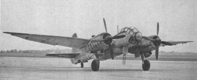
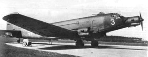
The Junkers Ju 388 was a 1944 development of the Junkers Ju 188. There were three versions, J (hunter), K (bomber) and L (reconnaissance aircraft).
The first prototype, the Ju 388 L-0 V 7 with the factory serial number 300,001, PG+YA, developed using of major components of the Ju 188 and flew for the first time in December 1943.
The prototypes built were V 1 to V 6 (2 each of the J-1, K-1 and L-1) during 1944. Structural areas and the horizontal tail unit of all versions were taken completely from the Ju 188, the chassis from the Ju 88. In contrast to the Ju 188 the Ju 388 possessed a pressurized cabin for three man crew.
In order to improve the aerodynamics and speed, the portion of the cockpit were omitted but a remote controlled tail FHL 131 Z was inserted. The wings were defrosted as with the Ju 188 by warm air by the engines, the snow and ice removal of the horizontal stabilizers took place via a gasoline Kaercher furnace.
The only version of this Ju 188 development to enter production before the end of the war was the Ju 388L reconnaissance aircraft, a small number of which were built. Power was provided by two 1,349kW BMW 801TJ engines.

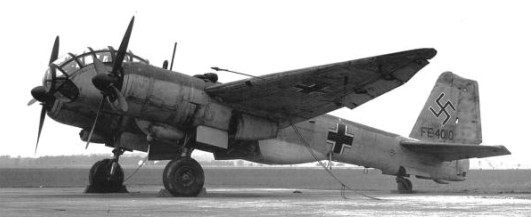
One Ju 388 L-1, 560,049 was captured by the Americans in the Merseburg works. It originated from production from Weser flight in Liegnitz/Schlesien, and parts were manufactured by ATG.
It was brought with other German airplanes on the aircraft carrier HMS Reaper in Operation Sea Horse for tests into the USA. These took place in Wright Field, Ohio. The machine carried the identification FE-4010 (later T2-4010).

In 1947 the tests finished, and 560,049 / FE-4010 found its way to the National Air & Space Museum. Unrestored, the cockpit of the Ju is 388 L is nearly in the original state.

Engines: 2 x Junkers Jumo 222E
Wingspan 22 m (72 ft. 2.125 in.)
Length 14.95 m (49 ft. 1 in.)
Height 4.9m (16 ft 1 in)
Weight 10,565 kg (23,296 lb.) empty
Top speed: 414 mph @ 37,700 ft.
Range: 1100 miles
Ceiling: 42,200 ft
Armament: 3 x 13mm mg

Junkers Ju.352

The Ju 352 development was based on wood in order not to use strategic materials. Power was provided by three 894kW Bramo 323R-2 engines. Production of this version totalled 43 or 44.

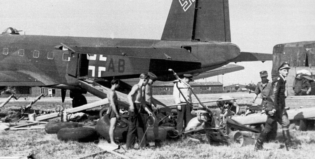
Ju 352 T9+AB at Juvincourt unloading AR234 equipment – Erich Sommer at right

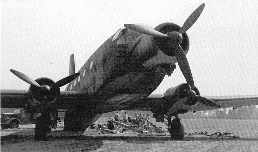
One of the features of the Ju 352 was its Trapoklappe hydraulically-operated loading ramp. Incorporating its own central stairway, this ramp, when lowered, raised the aircraft to a near horizontal position which facilitated easy loading and unloading. Another feature were its reversible pitch propellers.

T9+AB

A total of ten pre-production Ju 352 A-0s and 33 A-1 production aircraft were completed before construction was halted in September 1944.

A number of Ju 352 were delivered to Versuchsverband including T9+AB, T9+MB and T9+AL.

Gallery

Junkers Ju.322

A 1941 flying-wing transport glider, built in competition with the Me 321. The RLM insisted that the Ju 322 would be built of wood, a construction technique not used by Junkers since 1918.
Junkers employed a wing like that of the G 38 on a transport glider design, the Ju 322 Mammut (Mammoth) but stability problems showed up on its first test flight.

The RLM had ordered 200, but the Ju 322 was cancelled after the prototype proved unstable. The Me 321 was selected for production.

The 62 m (203 ft) span glider was towed by a Ju 90 towplane (for whose take off 5 km (3 miles) of forest had been cleared from the end of the Junkers airfield at Mersburg) and had to be cast off. It landed in a meadow where it lay for two weeks before it was towed back to the airfield by the two tanks it had been designed to carry. Both it and 99 other Mammuts under construction were sawn up into firewood.

Wing span: 62 m (203 ft)