Armstrong Whitworth AW.27 Ensign

The Ensign class of airliner was designed to an Imperial Airways specification for an aircraft capable of operating Empire routes to South Africa and Australia. The aircraft was proposed in two forms: the 40-seat ‘European’ or ‘Western’ (with 12 passengers in the front cabin, 4 in the card room, 12 in the middle cabin and 12 in the rear cabin, plus 3 toilets) and the 27-seat ‘Empire’ or ‘Eastern’ (with 3 cabins and 2 toilets) which could also be configured as a 20-passenger sleeper. Both versions were externally similar, being shoulder-wing monoplanes with the four 596kW Armstrong Siddeley Tiger IX radial engines mounted in the leading edges of the wings. The fuselage had a retractable undercarriage, each main leg carrying a single large Dunlop wheel.

The design was accepted and development proceeded, albeit at a interrupted pace thanks to the changing requirements put forth by Imperial Airways, coupledd with early engine reliability issues.

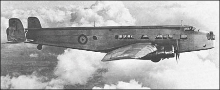
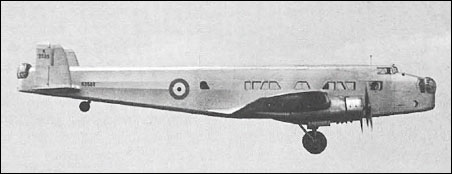
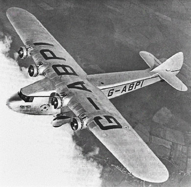
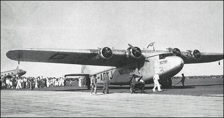
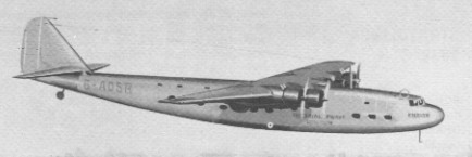
Design of the Ensign was characterized by its smooth lines and high-wing mounting. The cockpit was situated at extreme forward offering up good views past the wings which were seated to the middle of the fuselage, far back from the cockpit. Oval-shaped windows dotted the fuselage sides while the fuselage bottom sagged from nose to tail tip. The main landing gear were housed in the wing roots and consisted of large donut type wheels consistent with large aircraft design of the times. Four engines were placed two to a wing in the leading wing edges and contoured nicely into the wing elements. The empennage was of a traditional layout complete with rounded fin edges. Crew accommodations amounted to five personnel that included the pilot, co-pilot, radio operator and – if needed – two cabin stewards for passenger flight. Depending on the required range, passenger seating numbers fell between 27 and 40 total personnel.

The first A.W.27 flew on 23 January 1938 and from October it flew the London-Paris service. Production was slow but three more were completed in time for mail-carrying flights to Australia in late 1938. Due to engine troubles, all broke down well short of their goal.

The sixth production A.W.27 was fitted with 637kW Tiger IXC engines driving new de Havilland three-blade constant-speed propellers, and had a modified tail unit. This arrangement became standard on all the A.W.27s.

With the outbreak of World War II the A.W.27s were used to ferry RAF personnel initially to France and then between RAF stations within the UK with No. 24 Squadron. During this period several were destroyed or damaged by German fighters. In 1941 the surviving aircraft were re-engined with 671kW Wright R-1820-G102A Cyclone radials and were known as A.W.27A Ensign Mk IIs.
The AW.27 appeared in a single captured form with the Vichy French and later the Luftwaffe.
With the end of the war the airliners were scrapped.
Altogether 14 A.W.27s had been built.

Armstrong Whitworth AW 27 A Ensign
Engine: 4 x Armstrong Siddeley Tiger IX, 779 hp
Length: 114.173 ft / 34.8 m
Height: 23.031 ft / 7.02 m
Wingspan: 123.032 ft / 37.5 m
Wing area: 2449.886 sqft / 227.6 sq.m
Max take off weight: 48951.0 lb / 22200.0 kg
Weight empty: 32854.5 lb / 14900.0 kg
Max. payload weight: 9569.7 lb / 4340.0 kg
Max. speed: 177 kts / 328 km/h
Cruising speed: 147 kts / 272 km/h
Service ceiling: 18012 ft / 5490 m
Cruising altitude: 7005 ft / 2135 m
Wing load: 20.09 lb/sq.ft / 98.0 kg/sq.m
Range: 695 nm / 1288 km
Crew : 3+2
Payload : 27 pax

Armstrong Whitworth AW 27 A Ensign
Engines: 4 x Armstrong Siddeley Tiger IXC, 634kW
Take-off weight: 22226 kg / 49000 lb
Empty weight: 14392 kg / 31729 lb
Wingspan: 37.49 m / 122 ft 12 in
Length: 34.75 m / 114 ft 0 in
Height: 7.01 m / 22 ft 12 in
Wing area: 227.61 sq.m / 2449.97 sq ft
Max. speed: 330 km/h / 205 mph
Cruise speed: 274 km/h / 170 mph
Ceiling: 5485 m / 18000 ft
Range: 1384 km / 860 miles

Armstrong Whitworth AW.27 Ensign Mk I
Engines: 4 x Wright GR-1820-G102A radial, 1,100hp
Length: 114.17 ft (34.8m)
Wing span: 123.03 ft (37.50m)
Height: 23.03 ft (7.02m)
Maximum Speed: 205mph (330kmh; 178kts)
Maximum Range: 1,367miles (2,200km)
Rate-of-Climb: 900ft/min (274m/min)
Service Ceiling: 23,950ft (7,300m)
Accommodation: 5 + 27 to 40 passengers
Empty Weight: 35,053 lbs (15,900kg)
Maximum Take-Off Weight: 55,556 lbs (25,200kg)

A.W.27A Ensign Mk II
Engines: 4 x 671kW Wright R-1820-G
Wingspan: 37.49 m / 122 ft 12 in
Length: 34.75 m / 114 ft 0 in
Height: 7.01 m / 22 ft 12 in
Wing area: 227.61 sq.m / 2449.97 sq ft

Armstrong Whitworth Atlas

The Armstrong Whitworth Atlas was designed to replace the de Havilland DH.9A biplane of 1918 as well as the Bristol Fighter of 1916 against the RAF requirements of Specification 20/25. The Atlas design was intended to replace both airframes as the primary RAF “army co-operation” (mission liaison) mount. The Atlas was attributed to an engineering team led by John Lloyd who headed up design at the Armstrong Whitworth Aircraft firm as its Chief Designer.

Armstrong Whitworth and Lloyd’s design team initially undertook the Atlas project as a private venture, the prototype first flying on May 10th, 1925. The RAF then accepted the prototype for evaluation against other aircraft and the two-seat Atlas biplane proved a sound design save for some noticeable “sideslipping”. The issue was resolved with the fitting of new metal wings that featured sweepback. However, the new wings degraded the quality of the aircraft’s in-flight handling – then deemed excellent – and now showcased poor stall characteristics as well. As such, automatic slats were added to the wings and sweep was increased to an extent and, in the case of aircraft for the RCAF, the addition of ailerons on the lower wings. This rectified the less-than-stellar handling characteristics caused by the wing change.

Design was highly conventional for the time. The aircraft mounted its engine in a forward compartment to power the propeller system. The steel tube fuselage (fabric covered) was rather rounded in shape, thicker forward and tapering off at the rear. The wings were of an unequal span, single-bay biplane assemblies made of metal sporting slight dihedral on each unit, moreso in the lower assembly. The pilot sat direct aft of the upper wing assembly in an open-air cockpit with his observer/gunner in an open-air cockpit aft of the pilot. The empennage was relatively conventional in design, featuring a rounded vertical tail fin with a pair of horizontal stabilizers. The undercarriage varied based on sortie need – either a pair of wheels were set in a fixed undercarriage for land-based assignment or a set of long-running pontoon floats could be installed for at-sea work. Either way, the empennage was supported by a simple tail skid made particularly suitable for the land-based model. A hook could be optionally fitted to the fuselage underside to make quick pick-ups of ground messages without having the aircraft be required to land.

Standard armament for the series centered around a pairing of machine guns. A .303in (7.7mm) Vickers type machine gun was in a fixed position set to fire forward. A .303 (7.7mm) Lewis machine gun was mounted on a “Scarff ring” in the rear cockpit for trainable fire against emerging enemy threats from the rear. The flexible Scarff ring was developed in World War 1 by Britain Warrant Officer (Gunner) F.W. Scarff to address the armament needs of a rear gunner faced with the prospect of fighting the enemy from multiple angles from his open-air cockpit. In addition to the machine guns, the Atlas could be fitted with 112lb bombs under the wing elements.

Production of the Atlas began soon after with the aircraft formally introduced for service with the British Royal Air Force in 1927, an initial production batch numbering 37 aircraft. The Atlas entered service with 13 Squadron and 26 Squadron immediately and was eventually fielded with the overseas 208 Squadron out of Heliopolis, Egypt in 1930. It served in the mission liaison role – as well as trainer and communications – up until she was retired in 1935.

The initial production model became the Atlas I and some 271 examples were delivered to the RAF. Production lasted from 1927 to 1933 to which 478 were ultimately produced. 175 were dual-control advanced trainers.
The Atlas Trainer served as a dual-control mount in the training of future Atlas pilots.

These aircraft were to remain in service until 1934 in the army cooperation role, and as advanced trainers and communications aircraft into 1935.

Beyond British use, the Atlas was in the inventories of Canada, Egypt and Japan. The Atlas was eventually superseded by the Hawker Audax, based on the Hawker Hart biplane, and its trainer derivatives were themselves replaced by the Hawker Hart Trainer.

The Atlas II soon appeared as an improved Atlas model with more output from its Armstrong Siddeley Panther IIA engine of 525 horsepower/399kW, radio, message pick-up hook and cameras. However, the RAF elected to go with the competing Audax design and 15 of this model were delivered to the Chinese Air Force. Ajax represented Atlas I models with slight variations and only 4 were ever built for the RAF. Aries was a proposed and improved Atlas I model with slightly larger surfaces and overall dimensions while also being made easier to maintain in the field. However, only one was ever completed. The EAF Atlas was an export product for the Greek Air Force (Hellenic Air Force) that primarily differed in its selected engine, propeller and wing assemblies. At least 10 of this model were locally built by EAF (State Aircraft Factory) in Greece after 1931.

The last Armstrong Siddeley Atlas in RAF service was fielded by 208 Squadron, which replaced their aircraft with the newer Hawker Audax in 1935. Privately-held Atlas aircraft operated until 1938.

Atlas Mk I
Engine: 1 x Armstrong Siddeley Jaguar IVC, 450hp / 298kW.
Length: 28 ft 6.6 in (8.68m)
Wing span: 39 ft 6.6 in (12.04m)
Height: 10 ft 6 in (3.20m)
Empty Weight: 2,557 lbs (1,160kg)
Maximum Take-Off Weight: 4,028 lbs (1,827kg)
Endurance: 3.5 hr
Maximum Speed: 142mph (229kmh; 124kts)
Maximum Range: 400miles (644km)
Service Ceiling: 16,798ft (5,120m; 3.2miles)
Armament: 1 x 7.62mm Vickers mg, 1 x 7.62mm Lewis mg position
Up to 4 x 50kg bombs underwing
Crew: 2
Hardpoints: 4

Atlas Mk II
Engine: 399kW Panther IIA

Armstrong Whitworth AW.19

Air Ministry Specification G.4/31 called for a General Purpose aircraft, capable of level bombing, army co-operation, dive bombing, reconnaissance, casualty evacuation and torpedo bombing. The Vickers Type 253 won against the Fairey G.4/31, Westland PV-7, Handley Page HP.47, Armstrong Whitworth AW.19, Blackburn B-7, Hawker PV-4 and the Parnell G.4/31.
One prototype, first flown on 26 February 1934. No production.

Engine: 1 x 810hp Armstrong Siddeley Tiger VI
Take-off weight: 3969 kg / 8750 lb
Empty weight: 1950 kg / 4299 lb
Wingspan: 15.14 m / 49 ft 8 in
Length: 12.85 m / 42 ft 2 in
Height: 3.96 m / 12 ft 12 in
Wing area: 60.78 sq.m / 654.23 sq ft
Max. speed: 262 km/h / 163 mph
Ceiling: 6400 m / 21000 ft

Armstrong Whitworth AW.16

The Specification 21/26, issued by the Air Ministry’s Directorate of Technical. Development (DTD) on September 30, 1926, called for a “Single Seater Fighter Ship¬-plane for use from HM ships,” fitted with a land undercarriage which could be replaced by floats, and vice versa, within half an hour. The aircraft, which was to have an all metal structure but could be fabric covered, was to be suitable for launch from a catapult and for taking off from and alighting on the deck of an aircraft carrier.
Engines specified were the air cooled Bristol Mercury radial giving 550hp at 2,000rpm or the water cooled Rolls Royce Falcon X giving 480hp at 2,300rpm. A metal propeller was specified.
There was to be tankage for 74 gallons of fuel, plus an easily removed 20 gallon auxiliary tank and a gravity tank of sufficient capacity to allow half an hour’s flight at full power at ground level. An 11 gallon oil tank was to be provided if the Mercury engine was used, or an 8.5 gallon oil tank and a 2.5 gallon reserve water tank for the Falcon.
Alternative exhaust systems for day or night flying were required, and were to be easily changed.
Additional equipment to be carried during the acceptance flights weighed 5581b and included a Vickers 0.5in gun and 300 rounds, a Vickers 0.303in gun and 600 rounds, a rocket launching (R/L) tube and six bombs, and flotation gear. A second 0.303in gun with 600 rounds was to be provided for if the 0.5in gun was not available in time.
Minimum performance requirements with this load, using the Mercury, called for a horizontal speed of 132kt (152mph) at 10,000ft and a service ceiling of 23,000ft. With the Falcon X the figures were 127kt (146mph) at 10,000ft and 22,000ft. The length of run to take¬off was not to exceed 47ft in a relative wind of 28kt (32mph), and the aircraft was to become airborne at a speed of 55mph when catapulted in still air. The suitability for launching from a catapult or alighting on the deck of an aircraft carrier was “of first importance”, and the aircraft had to be capable of taking off from a turret or cruiser platform.
Despite the emphasis placed on the machine’s naval use, it was stressed that: “The aircraft is to be designed primarily as a landplane fighter and qualities required for this work are not to be sacrificed in order to improve its characteristics when equipped with the float alighting gear”.
A limit of 35ft was put on the wing span, the overall length was restricted to 23ft, the height was not to exceed 14ft 9in. Quick and easy removal and erection of the wings was specified, with the ability to remove the wing structure completely in ten minutes and replace it in fifteen minutes.
Tendering for this demanding specification were Armstrong Whitworth, which offered the AW XVI; Fairey, with the Flycatcher II; Gloster, which tendered the Gnatsnapper; Hawker, which offered the Hoopoe; Vickers, with a modified version of its Type 141 Scout; and George Pamall & Co.
Developed as a private venture to meet the requirements of both N.21/26 and F.9/26, the A.W.16 appeared in 1931. Two prototypes were flown. The first conforming to N.21/26 and the second to F.9/26, both being initially powered by the geared and supercharged Panther IIIA of 540hp. The second prototype was re-engined with a 565hp Panther VII during the course of trials at the A & AEE in 1933. Eighteen production examples of the A.W.16 were produced late in 1931, 17 of these for delivery to the Chinese Kwangsi Air Force and one being used as an engine test bed before being passed to the Alan Cobham circus. Armament comprised two 7.7mm Vickers machine guns.

Engine: Panther IIIA, 540hp
Take-off weight: 1597 kg / 3521 lb
Wingspan: 10.06 m / 33 ft 0 in
Length: 7.62 m / 25 ft 0 in
Height: 3.50 m / 11 ft 6 in
Wing area: 24.24 sq.m / 260.92 sq ft
Max. speed: 322 km/h / 200 mph

Armstrong Whitworth Aries

The only prototype was flown on 5 April 1930. No production. Aries was a proposed and improved Atlas I model with slightly larger surfaces and overall dimensions while also being made easier to maintain in the field. However, only one was ever completed.

Engine: 1 x 460hp Armstrong Siddeley Jaguar IV
Wingspan: 12.80 m / 41 ft 12 in
Length: 8.64 m / 28 ft 4 in
Height: 3.33 m / 10 ft 11 in
Wing area: 37.12 sq.m / 399.56 sq ft
Armament: 2 x 7.7mm machine-guns

Armstrong Whitworth AW.14 Starling

AW.14 Starling

Designed by J Lloyd to the Air Ministry specification F.9/26, the A.W.14 Starling was a staggered biplane with wings of unequal span and chord. Of fabric-covered rectangular-section steel-tube fuselage, the wings were steel spars, wooden ribs and fabric skinning. Two prototypes were ordered, the first flying on 19 May 1927 with an uncowled 385hp Armstrong Siddeley Jaguar VII two-row 14-cylinder radial. The engine was later replaced by a supercharged Jaguar IV rated at 410hp at 2745m and enclosed by a Townend ring cowling. Armament was two 7.7mm Vickers Mk II machine guns.
Competition in the F9/26 competition at Martlesham Heath against the officially sponsored Annstrong Whitworth Starling, Boulton-Paul Partridge, Gloster Goldfinch and Hawker Hawfinch, was the private venture Bristol Bulldog.
The Starling proved disappointing, and the second prototype was abandoned in favour of an entirely new design known as the Starling II.

AW.14 Starling II

The A.W.14 Starling II bore no relationship to the original Starling apart similar construction. Powered by an Armstrong Siddeley Panther IIIA 14-cylinder two-row radial rated at 540hp and armed with two Vickers Mk II machine guns, three prototypes were completed and flown in 1930, one being a shore-based fighter to the requirements of F.9/26 and the other two being private venture tenders to the N.21/26 fleet fighter specification. The land-based prototype had an uncowled engine and the shipboard prototypes featured Townend ring engine cowlings. No production orders were received.

Starling
Engine: Armstrong Siddeley Jaguar VII, 385hp
Take-off weight: 1404 kg / 3095 lb
Empty weight: 934 kg / 2059 lb
Wingspan: 9.55 m / 31 ft 4 in
Length: 7.67 m / 25 ft 2 in
Height: 3.20 m / 10 ft 6 in
Wing area: 22.89 sq.m / 246.39 sq ft
Max. speed: 286 km/h / 178 mph

AW.14 Starling II
Engine: Armstrong Siddeley Panther IIIA, 540hp
Take-off weight: 1463 kg / 3225 lb
Wingspan: 10.44 m / 34 ft 3 in
Length: 7.53 m / 24 ft 8 in
Max. speed: 295 km/h / 183 mph

Starling
AW.Starling II

Armstrong Whitworth Ape

To advance the science of aerodynamics, the Royal Aeronautical Establishment (RAE) commissioned an ‘infinitely adjustable’ aeroplane from Armstrong Whitworth, that by addition and adjustment of various parts would ‘provide all the answers’ to problems of aircraft design.
Named the Ape, the plane could be altered by varying the length and rake of various struts on, the wing position, stagger, gap and dihedral, and the fuselage length could be increased by inserting extra bays. The tailplane incidence could be altered in the air by the pilot by pulling levers in the cockpit, and the fin tilted along with the tailplane. Four different sizes and shapes of rudder and tailplane could be fitted. On the second aircraft an arrangement of struts was attached to the landing gear to prevent the propeller striking the ground if the Ape tipped forward.
The first Ape had a 180hp engine and performance was poor, limiting its utility. The second Ape was later fitted with a more powerful Jupiter engine, but increases in the weight largely nullified the effect of the greater power. It lasted for nine months of trials before crash-landing near Farnborough in May 1929.
A third aircraft was completed but saw little use, the RAE having become somewhat disenchanted with the whole idea.

Engine: 1 x 180hp Napier Lynx III radial piston engine
Take-off weight: 1225-1474 kg / 2701 – 3250 lb
Wingspan: 12.19 m / 39 ft 12 in
Length: 8.61/11.66 m / 28 ft 3 in / 38 ft 3 in
Height: 3.96/4.57 m / 12 ft 12 in / 14 ft 12 in
Max. speed: 145 km/h / 90 mph
Crew: 2