France Born in 1904 in the Vendée region of France, engineer Rene Couzinet graduated from the famed “Arts et métiers” school in Angers and began manufacturing aeroplanes in 1928 with the tri-motor monoplane Couzinet 10 Arc-en-Ciel prototype, designed for transatlantic flight.
The Couzinet 70, developed from the Couzinet 30, was also called Arc-en-Ciel and intended for Aeropostale’s transatlantic mail service to South America. After route-proving flight by Jean Mermoz in January 1933 it was extensively modified as Couzinet 71 and entered regular service in May 1934. Air Couzinet 10 of 1937 was totally unrelated twin-engined monoplane. Couzinet himself went to Brazil in the late 1930s, assisting with the development of that country’s aviation industry.
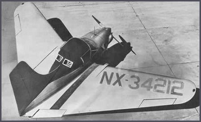
The Mallard (NX34212) was a forward swept-winged tailless monoplane with a 130 hp Franklin flat-four engine. With side-by-side two-seating it was demonstrated publicly by Alfred Reitherman. No production resulted. The 125 mph cruising speed quoted may have been projected rather than actual, considering it was described as 700 lb overweight and underpowered.
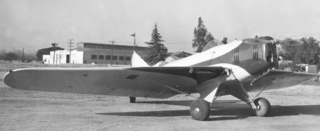
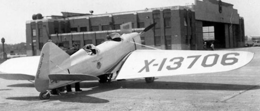
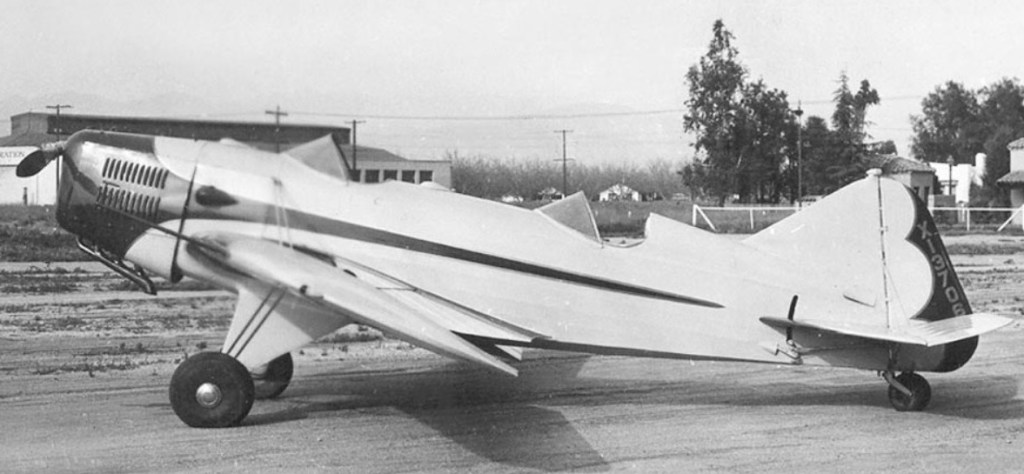
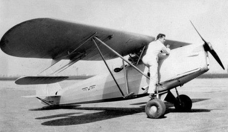
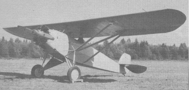
Continuing to experiment with a wing with a variable angle of attack (variable-incidence wing), American engineer George Wilbur Cornelius built his second aircraft in 1933, the designation LW-1 (from Low-Wing, and as a further development of the PW-1, from Parasol-Wing).
The low-wing two-seater LW-1 (X13706) used the short-lived four-cylinder inverted in-line 120 hp Martin 133 engine and had the same control system as the Cornelius FreWing. The incidence of the mainplanes was adjusted differentially like ailerons, and collectively like elevators in conjunction with a stabilator tailplane.
It was intended to improve performance by dispensing with the drag of the multiple strutting needed for its parasol predecessor.
The first aircraft of the Cornelius Aircraft Co, the FreWing, was designed by Cornelius and C.C. Spangenberger. It was a parasol monoplane single-seater in which the incidence of the mainplanes was adjusted differentially like ailerons, and collectively like elevators in conjunction with a stabilator tailplane. Initially, each mainplane had a servo surface extending behind it on two booms attached to the undersurface, but these were later removed as unnecessary.
Engine: 125 hp Menasco B-4 Span: 30 ft 6 in (9.30m) Length: 20 ft 6 in (6.25 m).
In the mid-1920 George Wilbur Cornelius started a program of experimentation on variable-incidence wings. No technical reports on the results of his work appear to have been published and little is known about the four types he produced. In 1930 George Wilbur Cornelius formed Cornelius Aircraft Co. at Glendale, California.
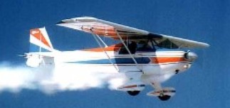
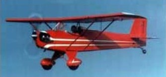
The Junior Ace is lightweight, easy to build, fun to fly and requires minimal maintenance. It has been modified from the original Corben Baby Ace so that it can utilize aircraft engines. The fuselage has also been widened, the horizontal stabilizer was modified for easier construction and modern aircraft wheels and brakes are now called for. With nearly a 34 ft wingspan and Clark Y airfoil, the Pober Junior Ace, designed by EAA founding president Paul Poberezny, is docile in stall and landing patterns. Airframe is 4130 steel tubing, wings are all wood and the recommended powerplant is a Continental C-85. Empty weight of the Junior Ace is 750 pounds and gross capacity is 1,320 pounds.
Junior Ace E
The Pober Junior Ace made its first flight with Captain Bud Judy at the controls. This first flight was successful and displayed the short field capabilities as well as low stall speed – ideal for small airstrips. The drawings for the airplane have full size wing rib drawings and two types of ailerons – the Friess aileron being a bit more responsive and lighter on aileron control. The indicated stall speed with one person on board is approximately 36 mpg. Indicated cruise with the Continental C-85-8 was a little over 80 mph. The Pober Junior Ace is open cockpit. The fuselage is chromoly steel tube, the tail group is chromoly steel tube and flat sheet stock to form ribs. The landing gear is chromoly tube with coil spring shocks. Wings are spruce spars and ribs. Two place side by side. The kit price in 2009 was US$20950.
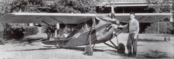
The Corben Baby Ace of 1929 was a professional design based on the Heath Parasol, but was a little more comfortable and had much better performance because of higher power. A 40-hp French Salmson AD-9 was used. Only six were factory-built, and a few were built from magazine plans in the 1930s.
The original Corben Baby Ace first flew back in 1931.
A single seat, high wing, sport plane powered by a modified Ford Model A 4 cyl inline engine. A simple and conventional design of open cockpit, strut-braced wing and tailplane, and a fixed, strutted, undercarriage. Later up-dated and marketed as the Pober Super Ace.
In 1954, Paul Poberenzy, who a year earlier had founded the still fledgling Experimental Aircraft Association, built a Baby Ace aircraft as a three part series in Mechanix Illustrated. The success of the articles caused an explosion in the homebuilt movement. The Baby Ace that Mr. Poberenzy built for Mechanix Illustrated is now in the EAA AirVenture Museum.
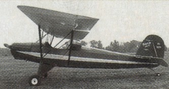
Corben Baby Ace D
The Baby Ace was extensively redesigned in 1955 as an ultralight monoplane specially designed for the amateur builder, the Baby Ace Model D. Baby Aces usually carry Continental engines rated from 65 to 85 hp and their performance is considered excellent by owners. Construction consists of a steel tube fuselage, all-wood wings and fabric covering. The wing is Clark Y mod from the root to the tip.
The Model C was refined by Ed Jacobs as the Model D. This first flew, as the DuCharme/EAA Baby Ace, on 16 November 1956.
In 1961 Ace Aircraft Mfg Co (Edwin T Jacobs), McFarland WI, purchased Baby Ace rights from Cliff DuCharme, West Bend WI.
Plans offered in 1968 for single-place Baby Ace ($28.50) and two-place Junior Ace, or Model E ($36.50). The kit price in 2009 was US$18950.
The Continental O-170 engine is the collective military designation for a family of small aircraft engines, known under the company designation of A50, A65, A75 and A80. The line was designed and built by Continental Motors commencing in the 1940s. It was employed as the powerplant for civil and military light aircraft
The horizontally opposed, four-cylinder engines in this family are all identical in appearance, bore, stroke, dry weight and piston displacement. All feature a bottom-mounted updraft carburetor fuel delivery system. The higher power variants differ only in compression ratio and maximum allowable rpm, plus minor modifications. The lower power versions are fully convertible to the higher rated versions.
1938 50 hp
In all models of this family of engines the cylinder heads are of aluminum alloy, screwed and shrunk onto steel barrels. Spark plug inserts and intake valve seats are made from aluminum-bronze alloy, while the exhaust valve seats are steel. The engines all employ hydraulic tappets which operate in aluminum guides that are machined into the crankcase. The tappets are built from four parts, a cam follower body, cup, cylinder and piston and operate with clearances of 0.03 in (1 mm) to 0.11 in (3 mm). The pushrods are steel and feature pressed-in ball ends.
Lubricating oil is delivered under pressure from the 4 US qt (4 lt) oil sump to the drive bearings and the crankpins though the crankshaft. The cylinder walls and pistons are spray lubricated. Normal operating oil pressure is 35 psi, with minimum idle oil pressure 10 psi.
Variants:
A50 50 hp (37 kW), Compression ratio 5.4:1, max rpm 1,900, fuel consumption at cruise 3.8 US gph
A65 65 hp (48 kW), Compression ratio 6.3:1, max rpm 2,300, fuel consumption at cruise 4.4 US gph. The exhaust valves have stellite faces. The pistons have three rings, although some early production A65s had four piston rings.
A65-8F 1939 (ATC 205) 65hp 171ci
A75 75 hp (56 kW), Compression ratio 6.3:1, max rpm 2,600, fuel consumption at cruise 4.8 US gph. The exhaust valves have stellite faces and the connecting rods have a 0.125 in (3 mm) hole drilled in the rod cap to improve lubrication. The pistons have three rings and smaller piston pins.
A80 80 hp (60 kW), Compression ratio 7.55:1, max rpm 2,700, fuel consumption at cruise 5.2 US gph. The connecting rods have a 0.125 in (3 mm) hole drilled in the rod cap to improve lubrication. The pistons have five rings and smaller piston pins. (ATC 217)
O-170 Military designation for the A55, A65, A75, A80 family of engines.