1807 Foster St
Chicago IL.
USA
In 1929 a Velie-powered N7600 Dragon Fly NAF-1 was registered with manufacturing credit to Dragon Fly Aircraft Co, 1807 Foster St, Chicago IL.
1807 Foster St
Chicago IL.
USA
In 1929 a Velie-powered N7600 Dragon Fly NAF-1 was registered with manufacturing credit to Dragon Fly Aircraft Co, 1807 Foster St, Chicago IL.
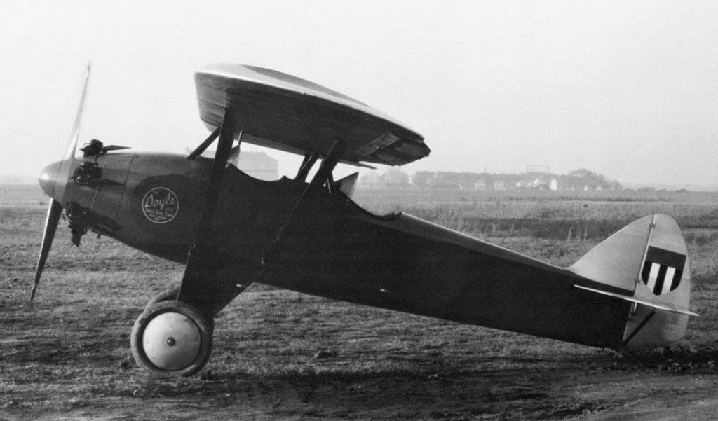
William Burke of the Vulcan Last Company backed the Wilson and Harvey Doyle plan to build a two-place, tandem, open-cockpit parasol sportplane and the Vulcan Aircraft Division began design work in a rented second floor room and construction in a former street car barn in Portsmouth.
The resulting Vulcan American Moth was a hit, but the relationship among the principles was deteriorating and the Doyle brothers left to start their own Doyle Aircraft Company in Baltimore. They produced fourteen Doyle Orioles which were similar to the Moth before bankruptcy ended the effort.
The prototype flew on 15 October 1928 with a yellow and black paint scheme and was priced at $2,975. Doyle Aero did not survive the Great Depression economy and ceased operations after a short production run. Harvey Doyle became an aeronautical engineer, and Wilson Doyle would become a professor of Political Science.
Seven of the O-2 Oriole and one O-3 Oriole were all built in 1928.
The last surviving O-2 serial number A-5 (NX9531) was restored in 1984 after being in storage since 1934 and identified by its designer Harvey Doyle.
Two brothers named Wilson and Harvey Doyle were 1925 graduates of Harvard and Yale respectively and moved to Portsmouth, Ohio, where William Burke of the Vulcan Last Company. Burke backed their plan to build a two-place, tandem, open-cockpit parasol sportplane and the Vulcan Aircraft Division began.
The result was the Vulcan “American Moth.” The plane was a hit, but the relationship among the principles was deteriorating and the Doyle brothers left to start their own Doyle Aircraft Company in Baltimore in 1929. They produced fourteen Doyle Orioles which were similar to the Moth before bankruptcy ended the effort.
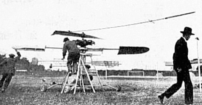
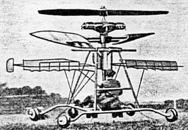
The Douheret helicopter of 1919 was the first helicopter with the engine placed between its two coaxial rotors.
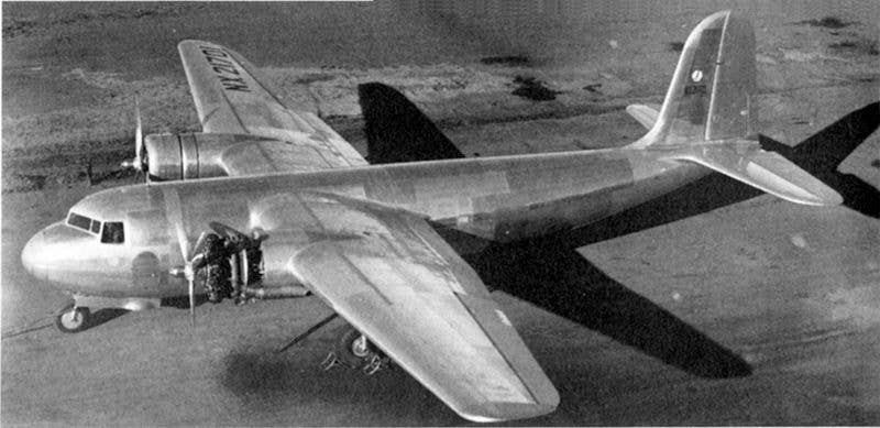
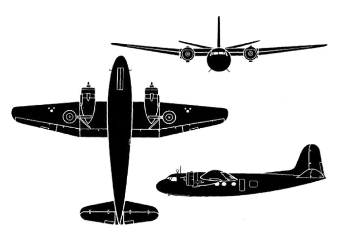
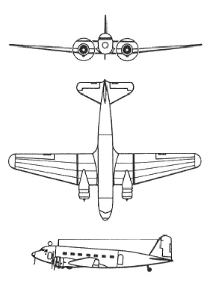
Designed at Douglas Aircraft Company’s El Segundo facility, the Douglas DC-5 was developed as a 16/22-passenger commercial transport for local service operations out of smaller airports. The DC-5 was a high-wing monoplane and featured the then relatively novel tricycle-type landing gear. With a design gross weight of 8391kg, the DC-5 was offered with either Pratt & Whitney R-1690 or Wright Cyclone radial engines.
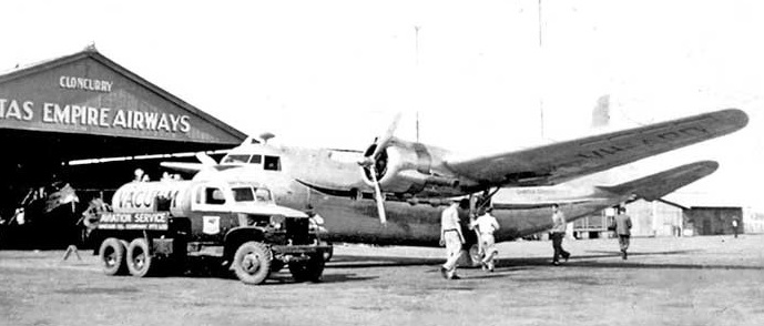
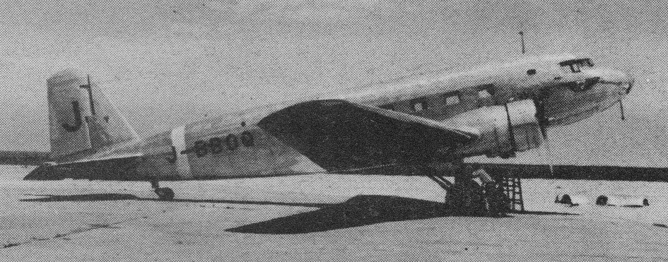
The prototype, powered by two 850hp Wright GR-1820-F62 Cyclones, flew for the first time on 20 February 1939, piloted by Carl Cover. Orders were placed by KLM (four aircraft), Pennsylvania Central Airways (six) and SCADTA of Columbia (two), but the programme was overtaken by the war and only the KLM aircraft were delivered. Although intended for service in Europe, two went first to the Netherlands West Indies to link Curacao and Surinam and the other two to Batavia in the Netherlands East Indies. All four were used to evacuate civilians from Java to Australia in 1942 and one, damaged at Kemajoran Airport, Batavia, on 9 February 1942, was captured by the Japanese and extensively test-flown at Tachikawa Air Force Base. The three surviving DC-5s were operated in Australia by the Allied Directorate of Air Transport and were given the USAAF designation C-110.
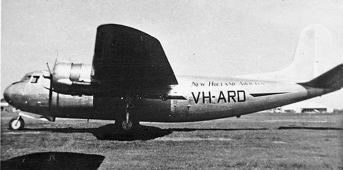
Still in one piece at Haifa (although engine-less) was Douglas DC-5, VH-ARD, carrying New Holland Airways (Sydney) insignia. On the nose was the name “Bali Clipper”.
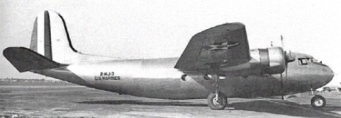
The earliest DC-5 military operations, however, were by the US Navy which had ordered seven examples in 1939. Three were R3D-1 16-seat personnel transports, the first of which crashed before delivery, and four were R3D-2 aircraft for the US Marine Corps with 1000hp R-1820-44 engines, a large sliding cargo door, and bucket seats for 22 paratroops. The prototype, after certification and development flying had been completed, was sold with a 16-seat executive interior to William E. Boeing, and was later impressed for US Navy use as the sole R3D-3.
Engine: 2 x 850hp Wright GR-1820-F62 radial
Max take-off weight: 9072 kg / 20000 lb
Empty weight: 6202 kg / 13673 lb
Wingspan: 23.77 m / 77 ft 12 in
Length: 19.05 m / 62 ft 6 in
Height: 6.05 m / 19 ft 10 in
Wing area: 76.55 sq.m / 823.98 sq ft
Max. speed: 356 km/h / 221 mph
Cruise speed: 325 km/h / 202 mph
Ceiling: 7225 m / 23700 ft
Range: 2575 km / 1600 miles
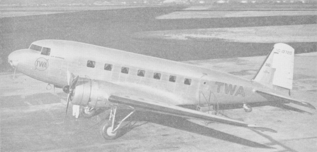
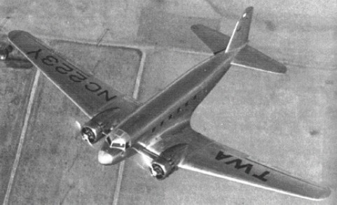
Design require¬ment to accommodate 14 passengers resulted in the DC-2, first flown on May 11 1934. Originally developed for TWA, it entered production in 1933 with 529kW Wright SGR-1820-F3 Cyclone engines.
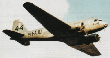
The first of 20 ordered by TWA flew on 11 May 1934 and deliveries started soon after. The early DC-2 were so successful that by June 1934 orders for 75 aircraft had been received from airlines in both the US and abroad. Subsequent orders were received from American Air Lines, Eastern Airlines, Pan American Airways and from numerous foreign operators – the first exported DC-2 being flown by KLM in the autumn of 1934.
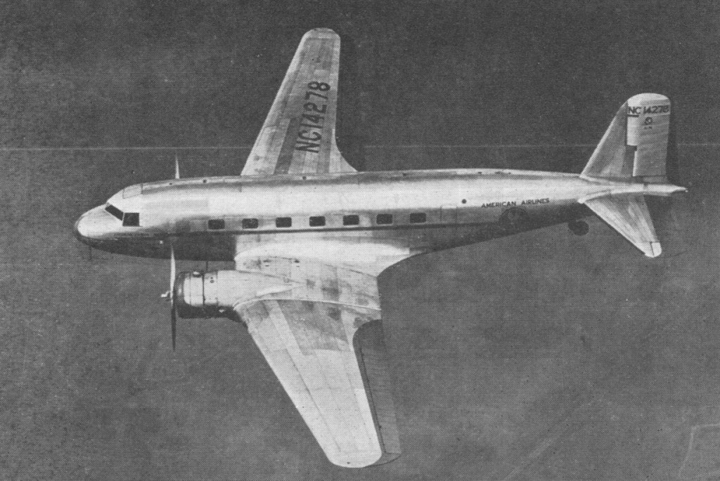
By September 1935 110 had been ordered and to meet the demand Douglas was producing one aircraft every three days. In 1934 Anthony Fokker acquired exclusive European rights to sell the Douglas Transport in Europe. In addition to commercial aircraft, DC-2 were purchased by the US Navy and USAAC and others were impressed into military service during World War II to serve with the Allied forces.

Usually powered by two 710 hp Wright R¬1820 Cyclone F series engines, the DC 2 seated 12 or 14 in airline service and 14 was a typical number of equipped troops for military versions. Deliveries of the latter began in 1935 with the US Army Air Corps C 32 and C 32A (24 delivered), followed by the R2D 1 of the Navy and Marine Corps. In 1942 civil DC 2s were impressed into Army Air Force service as the C 33. The eighteen C-33 had large cargo doors. A handful of aircraft formerly operated by European airlines served with the RAF, a few including the ex Polish LOT machines having Bristol Pegasus engines.
KLM DC-2 (PH-AKL) which crashed after take-off from Croydon Air Port near London, England on December 9th, 1936 taking the life of Juan de la Cierva y Codorníu, 1st Count of la Cierva,and 14 of 16 others aboard. The dead included Arvid Lindman, a former Prime Minister of Sweden, and the Austro-Hungarian fighter ace, Ludwig Hautzmayer, who was the aircraft’s pilot at the time.
In the mid-1930’s Japan obtained rights to produce the DC-2. It was built by Nakajima for civil airline use. Only a few reached military service, receiving the allied code name ‘Tess’.
35 were delivered to the USAF in 1939 with the DC-2 fuselage and DC-3 wing and tail assemblies, designated C-39.
DC-2
Engines: 2 x Wright Cyclone SGR-1820-F3, 710 hp
Later
Engines: 2 x Wright Cyclone SGR-1820-F52, 760 hp
Wingspan: 85 ft
Length: 61 ft / 11.75 in
Empty weight: 12,408 lb
Loaded weight: 18,560 lb
Max speed: 210 mph
Cruise: 190 mph
ROC: 1000 fpm
Engines: 2 x Wright R-1820-25, 710 bhp / 550kW
Max take-off weight: 8419 kg / 18561 lb
Empty weight: 5448 kg / 12011 lb
Wingspan: 25.9 m / 85 ft 0 in
Length: 18.9 m / 62 ft 0 in
Height: 4.9 m / 16 ft 1 in
Wing area: 87.2 sq.m / 938.61 sq ft
Max. speed: 320 km/h / 199 mph
Cruise speed: 300 km/h / 186 mph
Ceiling: 6100 m / 20000 ft
Range w/max.fuel: 1400 km / 870 miles
Crew: 2
Passengers: 14-16

In 1931 TWA Flight 599 crashed due to the failure of a wooden strut, which was caused by water which had dissolved the glue holding the layers together. The Civil Aeronautics Board ruled passenger aircraft could no longer contain wings or structural members (such as struts and spars) made of wood.
Boeing 247 production capacity was limited and they could only supply their primary contract, United Airlines. TWA wanted a similar aircraft, and asked four manufacturers to bid for construction of a three-engine, 12-seat aircraft to meet the specifications stipulated by the CAB:
All metal wings and structural members
Retractable landing gear
Capable of remaining in flight, even if one engine failed.
Donald Douglas was initially reluctant to participate in the invitation from TWA. He doubted there would be a market for 100 aircraft, the number of sales necessary to cover development costs. Nevertheless, he submitted a design consisting of an all-metal, low-wing, twin-engine aircraft seating 12 passengers, a crew of two and a flight attendant. The aircraft exceeded the specifications of TWA even with two engines. It was insulated against noise, heated, and fully capable of both flying and performing a controlled takeoff or landing on one engine.
Only one aircraft was produced in eight months, the prototype, X223Y. It made its maiden flight on July 1, 1933, flown by Carl Cover from Santa Monica in California, and was given the model name DC-1. During a half year of testing, it performed more than 200 test flights and demonstrated its superiority versus the most used airliners at that time, the Ford and Fokker Trimotors. It was flown across the United States, making the journey in a record time of 13 hours 5 minutes.
TWA accepted the model with a few modifications (mainly increasing seating to 14 passengers and adding more powerful engines) and ordered 20 aircraft. The production model was called the Douglas DC-2.
The DC-1 flew with TWA (Transcontinental and Western Air) until 1936 when Howard Hughes purchased the aircraft with a view to a world flight. Instead he used a faster Lockheed 14 for his 91 hour world circling flight.
The DC-1 was sold to Lord Forbes in the United Kingdom in May 1938, who operated it for a few months before selling it in France in October 1938. It was then sold to Líneas Aéreas Postales Españolas (L.A.P.E.) in Spain in November 1938. Later operated by Iberia Airlines from July 1939 with the name Negron it lost engine power on take-off and made a wheels-up landing at Malaga, Spain in December 1940 and was damaged beyond repair and later scrapped.
Powerplant: 2× Wright Cyclone SGR-1820F 9-cylinder radial, 710 hp (522 kW)
Length: 60 ft (18,28 m)
Wingspan: 56 ft (17,06 m)
Height: 16 ft 10 in (4.88 m)
Empty weight: 11,400 lb (5,171 kg)
Max takeoff weight: 17,500 lb (7,938 kg)
Maximum speed: 232 mph (373 km/h)
Cruise speed: 186 mph (300 km/h)
Range: 930 mi (810 nm, 1,500 km)
Service ceiling: 23,000 ft (7,010 m)
Crew: 2 pilots and flight attendant
Capacity: 12 passengers

In 1936 Douglas began its Model 7 as a light attack bomber as a private venture, produced to the order of the French government. Begun by Jack Northrop and completed by Ed Heinmann, after considerable refinement this flew on 26 October 1938 as the Model 7B private-venture prototype with 1,100-hp (820-kW) Pratt & Whitney R-1830 radials. The type was maneuverable and fast, and soon elicited a French order for 100 somewhat revised DB-7s.
Douglas DB-7 Boston / A-20 Havoc Article
The first production DB-7 flew on 17 August 1939. When France fell the undelivered aircraft outstanding from French contracts were taken over by the British government and given the name Boston. Only 60 were delivered, and 20 more passed to Great Britain.
Further French orders covered 100 DB-7As and 481 DB-7Bs. Most of these served with the Royal Air Force as Havoc Mk II night fighters and Boston Mk II bombers respectively. Later Bostons were patterned on A-20 aircraft for the US Army Air Forces, and served mainly over North-West Europe.
As delivered to the RAF from the French contracts, the Boston I was powered by two Pratt & Whitney R-1830-S3G-4G engines. It was used mainly for training duties, although some were converted for night fighting and given the British name Havoc. The A-20 was the first of the series built to a US Army specification and was powered by two 1,112kW Wright R-2600-7 Cyclone engines with exhaust-driven turbo-superchargers. It was fitted with American armament and equipment.
As the Boston II for the RAF, the A-20 had R-2600-A5B engines and British armament. Those converted into night fighters became Havocs each with a lengthened nose fitted with 12 forward-firing 7.62mm guns, AI radar and other special equipment depending on the sub-variant – one carried a high-power searchlight in the nose. As an intruder it carried a crew of three and full armament and bombs.
The A-20A for the USAAC/USAAF was powered by two 1,192kW Wright R-2600-11 engines with integral two-speed superchargers. The A-20B was an experimental development of the A-20A, armed with two 12.7mm guns firing forward, one 12.7mm upper flexible gun, one 7.62mm lower flexible gun, and one 7.62mm gun in the tail of each engine nacelle, firing aft. Nacelle guns were remotely controlled by a foot trigger in the rear compartment. The A-20C was powered by two similarly rated R-2600-23 engines. Armament comprised four fixed guns (two on each side of the transparent nose), two on a flexible mounting in the rear cockpit, and one in the lower rear-firing position – all 7.62mm (A20G) or 7.69mm (British Boston Ill). Ejector-type exhaust stacks replaced the collector rings used on the earlier models and range was increased by the addition of a self-sealing fuel tank in the forward and rear bomb-bay compartments. Provision was also made on some aircraft to carry a 900kg naval torpedo.

The observer (not only bomb aimer) was completely cut off from the pilot. Because of this the gunner had at the back a duplicate joystick. On high level operations a Vickers K gun was mounted in the rear entrance hatch. A camera was also carried mounted in this hatch.
It may be of interest that the very first operation carried out by the USA against Europe was on July 4, 1942, when six of their Bostons were led by six 226 Squadron Bostons.

The Boston III was powered by R-2600-A5B engines and carried a crew of four as a bomber. The Boston IIIA was similar but built by Boeing. Some Boston III/IIIA were fitted as intruders with four 20mm cannon under the forward fuselage, four 7.69mm guns in the nose, and two 7.69mm guns in the upper flexible position.
Following the experimental XA-20E, with a 37mm nose cannon and General Electric turrets, the A-20G appeared. This was similar to the A-20C except that the transparent bombardier nose was replaced by a solid nose fitted (in earlier versions) with four 20mm cannon and two 12.7mm machine-guns and ultimately with six 12.7mm guns. A few also had a single 12.7mm upper flexible gun, but this was soon replaced by a power-driven turret armed with two 12.7mm guns. Thicker armour for increased crew protection on ground-attack missions was also added.
The A-20H was powered by two 1,267kW R-2600-29 engines and incorporated minor improvements. The A-20J was identical to the later version of the A-20G except that the attack nose was replaced by a moulded-plastic bombardier’s nose incorporating bombing controls and flight navigation instruments. One in ten A-20G were completed as A-20J to serve as squadron lead planes. Armament consisted of two 12.7mm machine-guns (one in each side of the transparent nose), two in the power-operated dorsal turret and one in the lower rear firing position.
The A-20K was identical to the A-20H except that the attack nose was replaced by a bombardier’s nose, as with the A-20J. The British Boston V was similar. Special US versions of the A-20 appeared as the P-70 night fighter with R-2600-11 engines and armed with four 20mm cannon mounted in a fairing beneath the fuselage bomb bay; the P-70A conversion of the A-20G with R-2600-23 engines and six 12.7mm machine-guns in a solid nose and dorsal and lower guns; the P-70B development of the P-70A for training, with six 12.7mm ‘package’ guns and special radar (converted A-20G/J); the F-3A night photographic-reconnaissance conversion of the A-20J/K; and BD-1/2 target tugs for the US Navy.
Production for the RAF, USAAF, US Navy and Russia ceased on 20 September 1944 after 7,478 had been built (7008 by Douglas and 380 by Boeing). Russia received twice as many as the RAF and only some 800 less than the US Army.

Principal versions
DB-7 (R-1830)
DB-7A (Wright R-2600, many passed to Great Britain as Havoc Mk Is)
DB-7B (revised systems and larger vertical tail)
Boston Mk I (taken-over DB-7s)
Boston Mk II (taken¬over DB-7Bs converted to Havoc Mk I)
Boston Mk III (British DB-7Bs)
Boston Mk IIIA (200 Lend-Lease A-20Cs with British equip¬ment)
Boston Mk IV (169 Lend-Lease A-20Js with heavier fixed armament)
Boston Mk V (90 Lend-Lease A-20Ks with more power).
P-70 version of the A-20 became an early night fighter.
DB-7B / Boston Mk III
Engines: two 1,500-hp (1,119-kW) Wright R-2600-A5B Cyclone radial
Maximum speed 311 mph (500 km/h) at sea level
Initial climb rate 2,000 ft (610 m) per minute
Service ceiling 25,170 ft (7,670 m)
Range 525 miles (845 km)
Empty weights: 15,051 lb (6,827 kg)
Maximum take-off 21,580 lb (9,790 kg)
Wingspan 61 ft 4 in (18.69 m)
Length 47 ft 3 in (14.40 m)
Height 18 ft 1 in (5.51 m)
Wing area 464.0 sq ft (43.11 sq.m)
Armament: seven 0.303-in (7.7-mm) machine guns, and up to 2,000 lb (907 kg) of bombs.
A-20G Havoc
Engines: 2 x Wright R-2600-23 Cyclone 14, 1578 hp / 1193kW
Max take-off weight: 12338 kg / 27201 lb
Empty weight: 7250 kg / 15984 lb
Wingspan: 18.69 m / 61 ft 4 in
Length: 14.63 m / 47 ft 12 in
Height: 5.36 m / 17 ft 7 in
Wing area: 43.20 sq.m / 465.00 sq ft
Wing loading: 58.63 lb/sq.ft / 286.00 kg/sq.m
Max. speed: 275 kts / 510 km/h / 317 mph
Cruise speed: 200 kts / 370 km/h / 230 mph
Service ceiling : 25000 ft / 7620 m
Range: 891 nm / 1650 km / 1025 miles
Crew: 4
Armament: 9 x 12.7mm 50 MG (12,7mm) machine-guns, 1800kg of bombs
A-20K
P-70

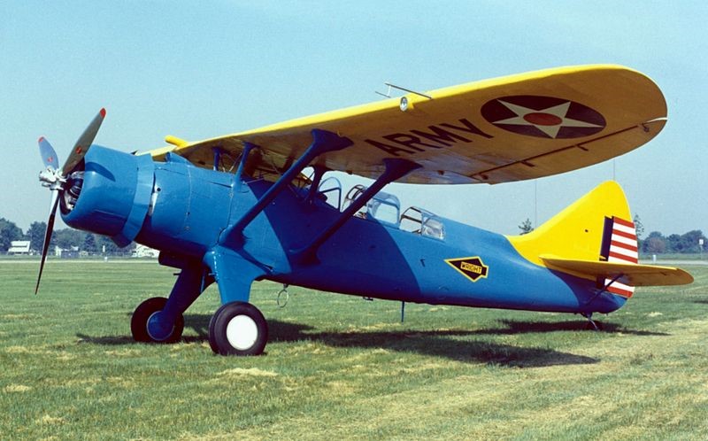
The Douglas O-46A was designed to operate from established airfields behind fairly static battle lines as in World War I. The O-46 was a development of the earlier Douglas O-43. The 24th airframe of the O-43A contract was completed as the XO-46 prototype, with a revised wing and an engine switch, from the O-43’s inline engine to a radial engine, the Pratt & Whitney R-1535-7.
First flying in 1935, the Air Corps ordered 90 O-46As in the same year. They were built between May 1936 and April 1937.
In 1939, a report was issued on the O-46A which stated that it was too slow and heavy to outrun and out-manoeuvre enemy fighter aircraft, too heavy to operate from small, wet, unprepared fields, and too large to conceal beneath trees. This report was a forecast of the future, for World War II with its rapidly changing battle lines proved the need for light, manoeuvrable observation aircraft which could operate from unimproved airstrips. Consequently, in 1942, the “O” (observation) designation was changed to “L” (liaison).
At least 11 O-46s saw overseas duty; two were destroyed in the Japanese raid on Clark Field in the Philippines on 8 December 1941. The Maryland Air National Guard operated O-46As off the coast of New Jersey for anti-submarine duty. The remainder were declared obsolete in late 1942 and after that were used primarily in training and utility roles.
A proposed variant with a Wright R-1670-3 engine received the designation O-48 but was not built.
On 27 November 1942, O-46A (s/n 35-179) was part of the 81st Air Base Squadron, when it landed downwind at Brooks Field, Harlingen, Texas, ran out of runway and overturned. Written off, it was abandoned in place. More than 20 years later it was discovered by the Antique Airplane Association with trees growing through its wings, and in 1967, it was rescued and hauled to Ottumwa, Iowa. Restoration turned out to be beyond the organization’s capability, and in September 1970, it was traded to the National Museum of the United States Air Force for a flyable Douglas C-47 Skytrain. The (then) Air Force Museum had it restored at Purdue University, and placed it on display in 1974, the sole survivor of the 91 O-46s built.
O-46A
Powerplant: 1 × Pratt & Whitney R-1535-7 Twin Wasp Junior, 725 hp (541 kW)
Propeller: 3-bladed metal propeller
Wingspan: 45 ft 9 in (13.94 m)
Wing area: 332 sq ft (30.8 m2)
Length: 34 ft 6.75 in (10.5347 m)
Height: 10 ft 8.5 in (3.264 m)
Empty weight: 4,776 lb (2,166 kg)
Gross weight: 6,639 lb (3,011 kg)
Maximum speed: 200 mph (320 km/h, 170 kn) at 4,000 ft (1,200 m)
Cruise speed: 171 mph (275 km/h, 149 kn)
Range: 435 mi (700 km, 378 nmi)
Service ceiling: 24,150 ft (7,360 m)
Rate of climb: 1,765 ft/min (8.97 m/s)
Wing loading: 20 lb/sq ft (98 kg/m2)
Power/mass: 1.087 hp/lb (1.787 kW/kg)
Guns: 2 × .30 cal (7.62 mm) Browning machine guns (one wing mounted and one flexible)
Crew: 2
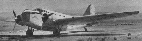
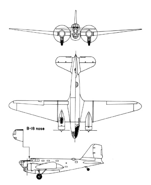
With a 1934 US Army Air Corps requirement for a bomber with greater capability than their Martin B-10, Douglas drew on engineering experience of the DC-2 commercial transport.
Private-venture prototypes to meet the US Army’s requirements were evaluated at Wright Field, Ohio, in August 1935, these including the Boeing Model 299, Douglas DB-1 and Martin 146. The first was built as the B-17 Flying Fortress, the last was produced as an export variant of the Martin B-10/B-12 series, and the Douglas DB-1 (Douglas Bomber 1) was ordered in January 1936 into immediate production under the designation B-18.
Derived from the commercial DC-2, the DB-1 prototype retained a basically similar wing, tail unit and powerplant. There were two differences in the wing: while retaining the same basic planform as the DC-2, the DB-1 had a 1.37m increase in span and was mounted in a mid-wing instead of low-wing position on an entirely new fuselage. The fuselage was deeper than that of the commercial transport to provide adequate accommodation for a crew of six, and to include nose and dorsal turrets, a bomb-aimer’s position, and an internal bomb bay. There was a third gunner’s position, with a ventral gun discharging via a tunnel in the underfuselage structure. Power was from two 694kW Wright R-1820-45 Cyclone 9 engines.
133 B-18s were covered by the first contract, including the single DB-1 which had served as a prototype. Production aircraft, which had the type name Bold, had equipment changes producing an increase in the normal loaded weight, and more-powerful Wright R-1820-45 radials. The last B-18 to come off the production line differed by having a power-operated nose turret, and carried the company identification DB-2, but this feature did not become standard on subsequent production aircraft.
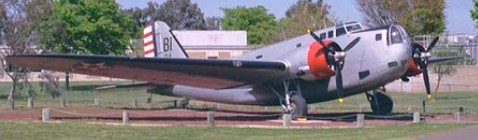
A second contract covered 217 B-18A aircraft, placed in June 1937 (177) and mid-1938 (40). This version differed by having the bomb-aimer’s position extended forward and over the nose-gunner’s station, and the installation of more-powerful Wright R-1820-53 engines. Most of the USAAC’s bomber squadrons were equipped with B-18s or B-18As in 1940, and the majority of the 33 B-18As which equipped the USAAC’s 5th and 11th Bomb Groups, based on Hawaiian airfields, were destroyed when the Japanese launched their attack on Pearl Harbor.
When in 1942 B-18s were replaced in first-line service by B-17s, 122 B-18As were equipped with search radar and magnetic anomaly detection (MAD) equipment for deployment in the Caribbean on anti-submarine patrols under the designation B-18B. The Royal Canadian Air Force also acquired 20 B-18As which, under the designation Digby Mk I, were employed on maritime patrol. The designation B-18C applied to two other aircraft reconfigured for ASW patrol. Another two aircraft were converted for use in a transport role under the designation C-58, but many others were used similarly without conversion or redesignation.
B-18A
Engines: 2 x Wright R-1820-53 Cyclone 9, 746kW / 986 hp
Max take-off weight: 12552 kg / 27673 lb
Empty weight: 7403 kg / 16321 lb
Wingspan: 27.28 m / 89 ft 6 in
Length: 17.63 m / 57 ft 10 in
Height: 4.62 m / 15 ft 2 in
Wing area: 89.65 sq.m / 964.98 sq ft
Wing loading: 28.70 lb/sq.ft / 140.0 kg/sq.m
Max. speed: 187 kts / 346 km/h / 215 mph
Cruise speed: 145 kts / 269 km/h / 167 mph
Service ceiling: 7285 m / 23900 ft
Range: 1043 nm / 1937 km / 1204 miles
Armament: 3 x 7.62mm (0.30in) machine-guns, 2948kg of bombs
Crew: 6