Technical Research Institute of Aviation Institute of Aviation
Institute of Aviation al. al. Krakowska 110/114 Krakow 110/114 02-256 Warszawa 02-256 Warsaw Poland
Aviation History of the Institute goes back to the beginnings of Polish independence, but the official start date of the Institute is 1 August 1926. In the initial phase of its operation, acted as the Institute of Technical Research Institute of Aviation. This name survived to the beginning of World War II. Activity in the period 1926-1939 focused primarily on testing and certification of aircraft. All the pre-war Polish military aircraft were tested and certified at the Institute, including the PZL P.11 , PZL.23 Karas , PZL.37 Moose , PZL.38 , and PZL.44 Wind.
In 1948 the Institute changed its name to the Central Institute of Aviation, and 1952 was named Institute of Aviation. In the post war period, constructors dealt mainly with the design and manufacture of licensed Po-2 and MiG-15. The Institute developed pulse motors and jets. In the early years of its operation activities of the Institute focused on the study of equipment derived from the Soviet Union and placed on the license production.
In 1946, the LWD Szpak , a year later, the first glider IS-1 Vulture , after which they were SZD-6 Bat , SZD-8 Swallow , SZD-9 Bocian , Marshmallow SZD-19 , SZD-24 Foka . The Institute of Tadeusz Sołtyk designed the PZL TS-8 Bies and the first Polish jet aircraft TS-11 Iskra , the engine designed in the Institute
Institute engineers also designed the first helicopter: BZ-1 GIL, BZ-4 Zuk and JK-1 Bumblebee. The Institute also, in 1972, designed and built a flying laboratory, the Lala-1. It was a heavily modified aircraft An-2 , which later tested technologies used in the construction of the PZL M-15 (Belphegor) .
In addition to aircraft construction facility began to specialize in designing and testing flying objects such as rockets and flying targets, including the Meteor 1 meteorological rocket project. Subsequent years of the Institute was developing a training-combat aircraft for the military, which resulted in the I-22 Iryda. The institute designed a four-seat, composite passenger aircraft, the I-23 Manager (flown in October 1998, for deliveries from 1999), two-seater trainer, the I-25 ace, two-seater helicopter patrol trainer IS-2 and a rescue patrol-hovercraft, the PRP-560 Ranger.
Proposed the Kobra 2000 in 1993 for air – to- ground combat operations in the next century, but abandoned.
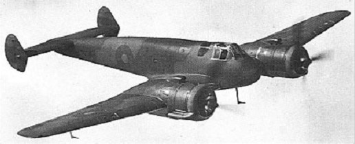
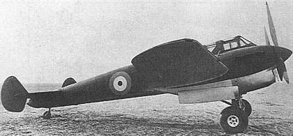
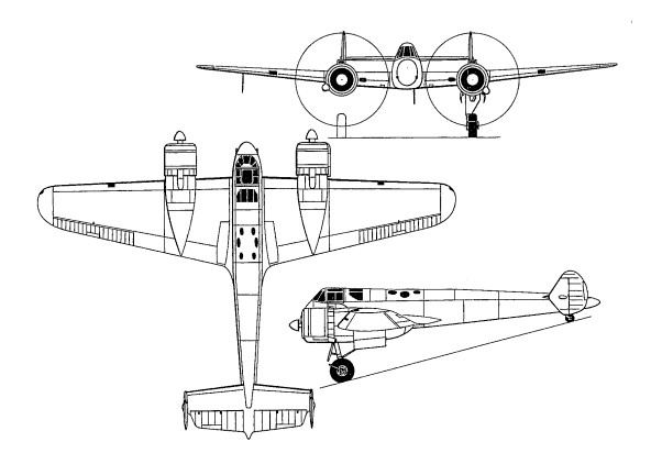
Designed by W G Carter to Specification F.9/37 calling for a twin-engined single-seater, this Gloster fighter was of all-metal stressed skin construction. It was intended to carry a fuselage-mounted armament of two 20mm Hispano cannon and four 7.7mm Browning machine guns.
Two prototypes were ordered, the first of these, powered by two 1050hp Bristol Taurus T-S(a) 14-cylinder radials, being flown on 3 April 1939. The aircraft attained a maximum speed of 579km/h at 4575m, but was badly damaged in a landing accident early in its flight test programme. When testing was resumed in April 1940, it had been re-engined with 900hp Taurus T-S(a) IIIs with the result that performance suffered, maximum attainable speed in level flight being reduced to 534km/h at 4630m. The second prototype, meanwhile, had been completed with 885hp Rolls-Royce Peregrine liquid-cooled engines, flying for the first time on 22 February 1940, and attaining a maximum speed of 531km/h during subsequent flight testing. Although the handling characteristics of Gloster’s F.9/37 contender were considered highly satisfactory and performance with the original engines had proved spectacular, no production was ordered.
Engine: 2 x Bristol Taurus T-S(a), 1050hp Max take-off weight: 5269 kg / 11616 lb Empty weight: 4004 kg / 8827 lb Wingspan: 15.24 m / 50 ft 0 in Length: 11.27 m / 36 ft 12 in Height: 3.53 m / 11 ft 7 in Wing area: 35.85 sq.m / 385.89 sq ft Max. speed: 579 km/h / 360 mph
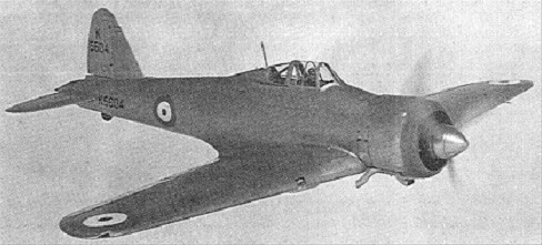
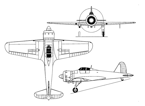
In 1935, to meet Air Ministry Specification F5/34, calling for a single seat monoplane interceptor armed with six or eight machine guns, a retractable undercarriage was required and an enclosed cockpit; a speed of at least 275mph (442kph) at 15,000ft (4,572m) was stipulated. This requirement was taken up by a number of firms. Bristol produced the Type 146 (835hp/622kW Bristol Perseus). Vickers brought their Jockey Mk II into approximate line with the requirements as the Venom (625hp/466kW Bristol Aquila). Henry Folland produced his last design for Gloster, the G.38 (840hp/626kW Bristol Mercury IX). None of the aircraft built to this specification achieved production status but ultimately produced the Hurricane and the Spitfire. The single-seat all-metal cantilever monoplane was powered by an 840hp Mercury IX nine-cylinder radial engine and carried an armament of eight 7.7mm Browning guns. This aircraft suffered a protracted development owing to the company’s preoccupation with the Gladiator. The first of two prototypes did not commence flight trials until December 1937, with the second following in March 1938. By the time that the Gloster fighter made its debut, the Hurricane had entered service and the Spitfire had reached production, and further development of the Mercury-engined monoplane was not pursued.
Engine: Bristol Mercury IX, 840hp/626kW Max take-off weight: 2449 kg / 5399 lb Empty weight: 1900 kg / 4189 lb Wingspan: 11.63 m / 38 ft 2 in Length: 9.76 m / 32 ft 0 in Height: 3.09 m / 10 ft 2 in Wing area: 21.36 sq.m / 229.92 sq ft Max. speed: 508 km/h / 316 mph
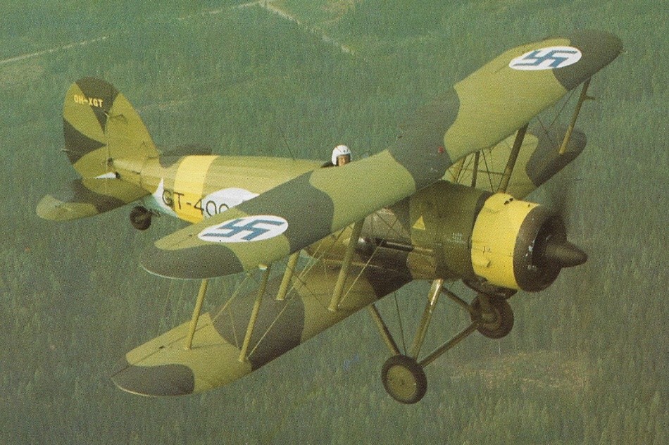
Specifications F.9/26 and F.20/27 remained unfulfilled; and F.7/30 calling for a 402km/h four-gun fighter seemed initially even more unlikely to be attained. Gloster’s first submission had been an improved version of the all-metal Goldfinch, and with the progression of time this design had been subjected to several permutations of airframe innovations and differing engines. When, in 1933, Gloster’s SS.19B demonstrated a maximum speed of 346km/h during tests at Martlesham Heath, it was ordered into production under the name Gauntlet I. During the period 1935 to 1937 Gauntlets were the fastest fighters in RAF service, partially replaced by Gladiators and Hurricanes in 1938 and finally ousted by Spitfires in 1939. Aircraft produced from 1935, after Hawker Aircraft had taken over the Gloster company, were constructed according to Hawker production methods, bringing changes to wing spar and fuselage structure. These differing aircraft were designated Gauntlet II.
Gloster Gauntlet Mk.II GT-400
Last open-cockpit biplane in RAF service, the Gauntlet equipped 14 squadrons at its peak period of usage. It was during this same period that a very different performance was given under most secret conditions when (in November 1936) three of No 32 Squadron’s Gauntlets intercepted a civil airliner under the guidance of an experimental ground-radar installation at Bawdsey Manor, Suffolk. Thus the Gauntlet has the distinction of carrying out the world’s first radar-controlled interception.
Gloster SS 19 B Gauntlet Engine: Bristol Mercury VI S.2, 631 hp Length: 26.411 ft / 8.05 m Height: 10.236 ft / 3.12 m Wingspan: 32.776 ft / 9.99 m Wing area: 314.955 sq.ft / 29.26 sq.m Max take off weight: 3971.2 lb / 1801.0 kg Weight empty: 2769.5 lb / 1256.0 kg Max. speed: 200 kts / 370 km/h Service ceiling: 33497 ft / 10210 m Wing load: 12.71 lb/sq.ft / 62.0 kg/sq.m Range: 400 nm / 740 km Crew: 1 Armament: 2x cal.303 MG Vickers (7,7mm)
Gauntlet Mk II Engine: 1 x Bristol Mercury VIS2, 477kW Max take-off weight: 1801 kg / 3971 lb Empty weight: 1256 kg / 2769 lb Wingspan: 9.99 m / 32 ft 9 in Length: 8.05 m / 26 ft 5 in Height: 3.12 m / 10 ft 3 in Wing area: 29.26 sq.m / 314.95 sq ft Max. speed: 370 km/h / 230 mph Ceiling: 10210 m / 33500 ft Range: 740 km / 460 miles Armament: 2 x 7.7mm machine-guns
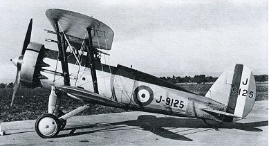
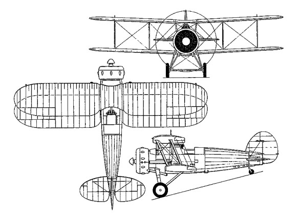
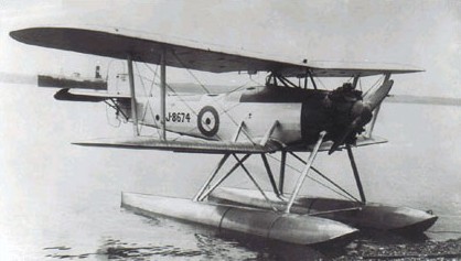
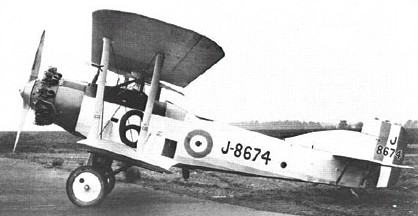
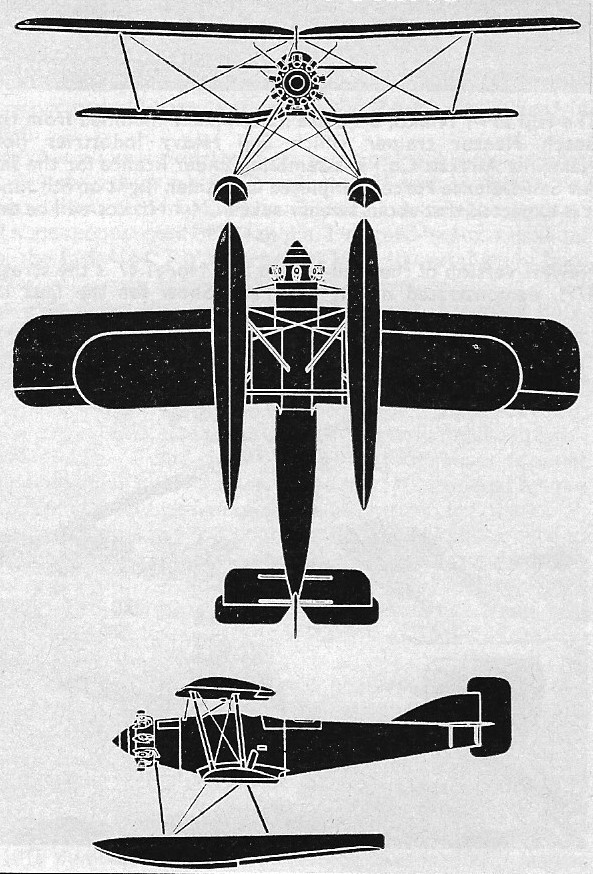
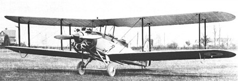
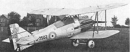
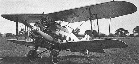
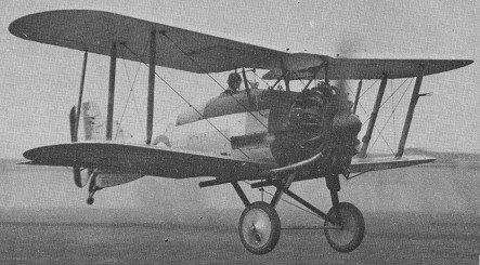
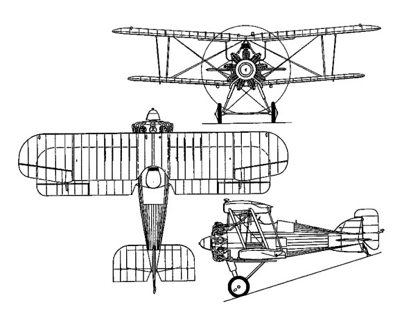
The Gloster Goring was a private venture to replace the Hawker Horsley, then (1927) in service as a light bomber with the RAF. The Air Ministry intimated that the engine they would like to see installed was the Bristol Orion fitted with an exhaust-driven supercharger. One airframe was so equipped, but due to the failure of the Orion and its supercharger, this variant was not proceeded with.
Another Goring, powered with a Bristol Jupiter 8-geared engine, met with much more success.
As a bomber, the Goring carried 700 lb of bombs and in addition the observer had a Vickers machine gun on a rotating mount in the rear cockpit. Provision was made for a second gun firing through the bottom of the fuselage. In this condition the Goring had an endurance of 6 hr 30 min at 15,000 ft.
At a later stage the Goring was converted to a twin-float seaplane, still powered by a Jupiter 8. This decreased the maximum speed by only 4 mph and made similarly small alterations to performance figures of the landplane. The floats were of Gloster design and were made entirely of anodised duralumin.
Although the second aircraft was taken over by the Ministry for research work in connection with engines, the type was not ordered into production.
Goring (landplane) Engine: 1 x 425hp Bristol Jupiter VI Max take-off weight: 2440 kg / 5379 lb Empty weight: 1323 kg / 2917 lb Wingspan: 12.80 m / 41 ft 12 in Length: 9.14 m / 29 ft 12 in Height: 3.51 m / 11 ft 6 in Wing area: 41.81 sq.m / 450.04 sq ft Max. speed: 219 km/h / 136 mph Ceiling: 5029 m / 16500 ft Armament: 2 x 7.7mm machine-guns Crew: 2
Engine: 1 x 420hp Bristol Jupiter V or 425hp Jupiter VIA Max take-off weight: 2272 kg / 5009 lb Empty weight: 1336 kg / 2945 lb Wingspan: 14.20 m / 46 ft 7 in Length: 9.60 m / 31 ft 6 in Height: 3.45 m / 11 ft 4 in Wing area: 45.89 sq.m / 493.96 sq ft Max. speed: 208 km/h / 129 mph Range: 1208 km / 751 miles Crew: 2 Armament: 2 x 7.7mm machine-guns, 2 x 10⁵kg bombs
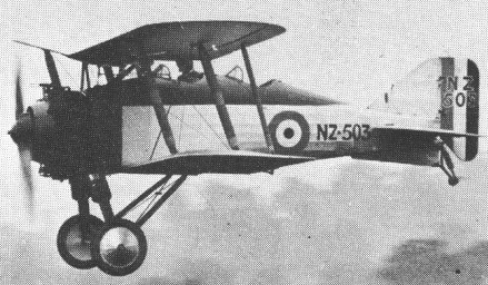
In 1923 Gloster built a two-seat private-venture research aircraft which became known as the Grouse, to carry out flight evaluation of new and special biplane wings. Simultaneously a single-seat version was built. When demonstrated to Air Ministry officials, its performance was considered to be so impressive that three prototypes were ordered. The first of these became the Grebe prototype which, following evaluation, was ordered into production under the designation Grebe II. This differed from the two-seat version by having a more powerful Jaguar IV engine (instead of a Jaguar III) and several other modifications.
The Grebe entered service in October 1923 with the RAF’s No 111 Squadron, and total production numbered 113 aircraft, including a small number of two-seat dual-control trainers. The Grebe was found to have wing flutter problems, resulting in the addition of outward-sloping Vee struts to brace the overhang of the upper wing. Two Grebes were modified during 1926 with special release attachments on the top surface of the upper wing. This allowed them to be carried into the air beneath the keel of the British rigid airship R-33, and used for launching experiments.
Grebes remained in service until their replacement by Armstrong Whitworth Siskins in mid-1928.
Grebe Mk II Engine: 1 x Armstrong Siddeley Jaguar IV, 385-425 hp Max take-off weight: 1189 kg / 2621 lb Empty weight: 780 kg / 1720 lb Wingspan: 8.94 m / 29 ft 4 in Length: 6.17 m / 20 ft 3 in Height: 2.82 m / 9 ft 3 in Wing area: 23.60 sq.m / 254.03 sq ft Max. speed: 243 km/h / 151 mph @ SL Ceiling: 7010 m / 23000 ft Armament: 4 x 7.7mm forward-firing machine-guns Crew: 1
Gloucestershire Aircraft’s first military aircraft of all-metal construction was the third prototype Gorcock single-seat fighter resulting from a May 1924 Air Ministry contract for three prototypes powered by the Napier Lion 12-cylinder water-cooled engine. The first two combined a steel fuselage with wooden wings and the third had an all-steel structure. The first mixed-construction Gorcock was powered by a 450hp geared Lion IV and was flown mid-1925, the second Gorcock having a 525hp direct-drive Lion VIII. Engine difficulties prevented their delivery until 1927, together with the all-metal third Gorcock which had a Lion IV. All three aircraft carried the standard armament of twin synchronised 7.7mm Vickers guns and were used for research and development flying, no production being ordered. Although 72kg heavier than the mixed-construction prototypes, the all-metal prototype was 16km/h faster.
Prototype 3 Max take-off weight: 1514 kg / 3338 lb Empty weight: 1099 kg / 2423 lb Wingspan: 8.69 m / 28 ft 6 in Length: 7.94 m / 26 ft 1 in Height: 3.10 m / 10 ft 2 in Wing area: 23.22 sq.m / 249.94 sq ft Max. speed: 280 km/h / 174 mph
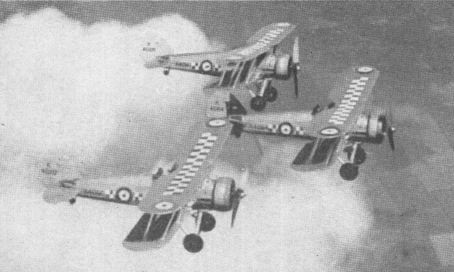
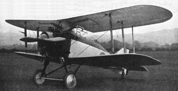
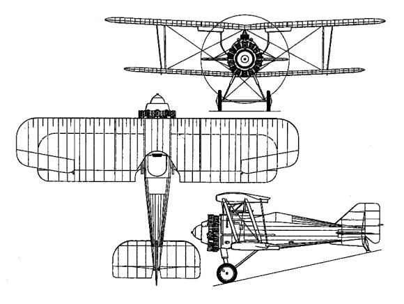
A development of the Gloster Grebe fighter, the Gamecock was initially to Specification 37/23, a re-engined variant of the Grebe using the new 398hp Bristol Jupiter IV radial engine. Of wooden construction with fabric skinning and retaining the then-standard armament of two synchronised 7.7mm Vickers guns. Ordered originally as the Grebe II in August 1924, the prototype Gamecock 1 (as it became titled) was delivered to Martlesham Heath for service tests on 20 February 1925. Trial reports were enthusiastic, resulting in an initial order for 30 production Gamecock Is machines in September 1925 powered by the 425hp Jupiter VI. First to take delivery of the production Gamecocks was 23 Squadron RAF, at Hen¬low, in May 1926; followed by 3, 17, 32 and 43 Squadrons. Although designed for day fighting, the Gamecocks issued to 3 and 17 Squadrons were specially modified for night interception duties. During the next five years, Gamecocks were prominent in the many public displays organized by the RAF, and demonstrated the type’s manoeuvrability in many superb aerobatic exhibitions. A further 60 Gamecock Is were built for the RAF (1925-27), one of these (unofficially known as the Gamecock III) at one time flying with a lengthened fuselage, new and enlarged fin-and-rudder assembly and narrow-chord ailerons.
Gamecock II
The Gamecock recorded a relatively high accident rate in service use; 22 having crashed within 19 months of its introduction to the RAF, and killing eight pilots. A variety of modifications were embodied progressively to eliminate the Gamecocks’ tendencies to spin abruptly and give wing flutter at high speed. Despite such characteristics, service Gamecocks quickly demonstrated their fast performance by tak¬ing the first three places in the 1927 Sassoon Cup Race for RAF fighter squadrons. A developed version, the Gamecock II, with a steel-tube upper wing centre section, narrow-chord ailerons and a larger rudder, appeared in 1928. This was adopted by Finland, two pattern aircraft and a manufacturing licence being acquired. Fifteen Gamecock IIs were built for the Finnish air arm 1929-30 by the State Aircraft Factory (Valtion Lentokonenetehdas), these having the lengthened fuselage tested earlier in the UK by the so-called Gamecock III and being powered initially by the 420hp Gnome-Rhone Jupiter (IV) 9Ab or 9Ak and later by the 480hp Jupiter (IV) 9Ag. By 1929 licensed production of the design (renamed Kukko) began at Helsinki. One unit, Fighter Squad¬ron 24, continued to fly this variant from 1929 until 1935; while one Finnish Gamecock (GA¬46) remained in service until late 1944.
Though development of the basic Gamecock was undertaken, resulting in the Gamecock II and III, the latter saw no service use. In 1928 the Finnish government, having been much impressed by various dis-plays of the Gamecock’s versatility, placed an order for the type.
Last of the all wood construction fighters in RAF use, the Gamecock achieved fame in perpetuity when the reformed 43 Squadron adopted a fighting cock as its chosen official badge motif; the unit being known ever since as ‘The Fighting Cocks’.
The last Gamecock Is were withdrawn from first-line RAF service mid-1931, Gamecock IIs remaining first-line Finnish equipment until 1935. In total 108 were built.
Gamecock Mk I Engine: 1 x Bristol Jupiter VI, 317kW Max take-off weight: 1299 kg / 2864 lb Empty weight: 875 kg / 1929 lb Span: (upper) 9.07 m (29 ft 9.5 in) Spun (lower) 7.89 m (25 ft 11 in) Length: 5.99 m / 19 ft 8 in Height: 3.06 m / 10 ft 0 in Wing area: 34.63 sq.m / 372.75 sq ft Max. speed: 249 km/h / 155 mph Ceiling: 6736 m / 22100 ft Armament: 2 x 0.303 in (7.7 mm) Vickers Mk 1, 1200 rounds. Endurance: 2.5 hr at 4572 m (15000 ft)
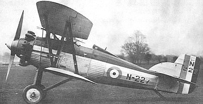
The Specification 21/26, issued by the Air Ministry’s Directorate of Technical. Development (DTD) on September 30, 1926, called for a “Single Seater Fighter Ship¬-plane for use from HM ships,” fitted with a land undercarriage which could be replaced by floats, and vice versa, within half an hour. The aircraft, which was to have an all metal structure but could be fabric covered, was to be suitable for launch from a catapult and for taking off from and alighting on the deck of an aircraft carrier. It was to have a good degree of positive stability about all axes in both configurations, and tail incidence had to be adjustable in flight to enable the aircraft to fly horizontally at all speeds without attention from the pilot. It was to be “highly controllable” at all speeds, and especially close to stalling speed, with no tendency to ‘hunt’ in a steep dive. Control had to be adequate to stop an incipient spin when the machine was stalled. A high degree of manoeuvrability in the air and on the ground or water was desired, and it had to respond quickly to the controls while not being tiring to fly. The ailerons were to have the minimum of yawing effect. As a seaplane, the machine was to have good static stability in the water, and when under tow or running under its own power it was to be stable about all axes at all speeds. Engines specified were the air cooled Bristol Mercury radial giving 550hp at 2,000rpm or the water cooled Rolls Royce Falcon X giving 480hp at 2,300rpm. The installation had to allow for rapid and easy removal of the engine. The cowling, which also had to be easily removable, had to be finished “to prevent the reflection of light which might betray the presence of the aircraft to the enemy or dazzle the pilot”. A metal propeller was specified. There was to be tankage for 74 gallons of fuel, plus an easily removed 20 gallon auxiliary tank and a gravity tank of sufficient capacity to allow half an hour’s flight at full power at ground level. An 11 gallon oil tank was to be provided if the Mercury engine was used, or an 81/2 gallon oil tank and a 21/2 gallon reserve water tank for the Falcon. Alternative exhaust systems for day or night flying were required, and were to be easily changed. The night flying system had to provide adequate silencing and flame damping, while the daytime system was to be “of minimum weight”. Additional equipment to be carried during the acceptance flights weighed 5581b and included a Vickers 0.5in gun and 300 rounds, a Vickers 0.303in gun and 600 rounds, a rocket launching (R/L) tube and six bombs, and flotation gear. A second 0.303in gun with 600 rounds was to be provided for if the 0.5in gun was not available in time. Minimum performance requirements with this load, using the Mercury, called for a horizontal speed of 132kt (152mph) at 10,000ft and a service ceiling of 23,000ft. With the Falcon X the figures were 127kt (146mph) at 10,000ft and 22,000ft. The length of run to take¬off was not to exceed 47ft in a relative wind of 28kt (32mph), and the aircraft was to become airborne at a speed of 55mph when catapulted in still air. The suitability for launching from a catapult or alighting on the deck of an aircraft carrier was “of first importance”, and the aircraft had to be capable of taking off from a turret or cruiser platform. For fighting, the pilot was to have the best possible view in all directions, and a good view forward and downwards was required for carrier landings. A clear, unobstructed view forward over the machine’s centreline was needed to enable him to sight the fixed guns, the installation of which was to dispense with blast tubes. There was also to be provision for the fitting of a G.3 aerial camera as near to the sights as practicable, and standard clips were to be fitted to allow the new “light carrier” to be installed to carry four 20 lb bombs, sufficient clearance being provided to enable the bombs to be released in a very steep dive. Despite the emphasis placed on the machine’s naval use, it was stressed that: “The aircraft is to be designed primarily as a landplane fighter and qualities required for this work are not to be sacrificed in order to improve its characteristics when equipped with the float alighting gear”. A padded head support was to be provided to prevent injury to the pilot during catapult launch acceleration. A limit of 35ft was put on the wing span, the overall length was restricted to 23ft, the height was not to exceed 14ft 9in. Quick and easy removal and erection of the wings was specified, with the ability to remove the wing structure completely in ten minutes and replace it in fifteen minutes. The contractor was required to provide a full size mock up of his proposed aircraft before constructional work was begun, to enable the Director of Technical Development to examine and approve the layout. This mock up had to include “all parts and components which are likely to interfere with the all round view of the pilot”, and was to show the internal arrangement of the cockpit. Scale model floats for official water tank tests were also to be provided, along with specimens of ribs, a section of wing, and a length of spar. Tendering for this demanding specification were Armstrong Whitworth, which offered the AW XVI; Fairey, with the Flycatcher II; Gloster, which tendered the Gnatsnapper; Hawker, which offered the Hoopoe; Vickers, with a modified version of its Type 141 Scout; and George Pamall & Co. Designed by Henry Folland, the first of two Gnatsnapper prototypes, temporarily powered by a Jupiter VII engine, flew in February 1928. The Mercury IIA was subsequently installed, but as this did not measure up to anticipated performance or reliability, the Jupiter VII was reinstated for official trials. The second prototype was not completed until March 1930, initially with a Mercury IIA, but the designated power plant was again discarded shortly thereafter. The first prototype was re-engined with a 540hp Armstrong Siddeley Jaguar VIII 14-cylinder radial as the Gnatsnapper II, but suffered damage during official trials. None of the aircraft tendered to Specification 21/26 won a production contract. In 1931, the Gnatsnapper was re-engined once more, with a steam-cooled 525hp Rolls-Royce Kestrel IIS, as the Gnatsnapper III, subsequently serving as a Rolls-Royce test-bed and hack aircraft.
Max take-off weight: 1644 kg / 3624 lb Empty weight: 1347 kg / 2970 lb Wingspan: 10.21 m / 33 ft 6 in Length: 7.48 m / 24 ft 6 in Height: 3.32 m / 10 ft 11 in Wing area: 33.44 sq.m / 359.94 sq ft Max. speed: 265 km/h / 165 mph