The first reference to a Polikarpov twin-engine model capable of executing bomber actions comes from the first half of 1936. This sketch would originally receive the name VT or Vozduzhni Tank (Flying Tank), which would later become MPI (Mnogomiestni Puchechni Isterbitiel or Multiseat Gunship Fighter) and SVB (Samoliot Vozduzhnovo Buoy or Air Combat Plane).
At the beginning of February, at one of the government meetings, Polikarpov learned that the OKB-2 collective, under the direction of Shpitalni, had developed a powerful 37 mm automatic cannon with a high muzzle velocity. Unfortunately, this weapon had not been tested due to the absence of an aircraft capable of using it.
In turn, Polikarpov reported that his group had developed a development of the TsKB-44 model with excellent technical specifications that could be ideally used as an aerial gunship intended to combat armored formations.
In this way, the idea of creating the new model according to Shpitalni himself constituted “…the synthesis of the achievements of the OKB-2 in automatic weapons, Polikarpov ‘s research in aviation aerodynamics and Polikarpov’s group of colleagues in the direction of automatic weapons”.
Shortly after this meeting, at Factory No.39 Polikarpov would develop three versions of the new aircraft that Polikarpov began to call VIT (Vozduzhni Isterbitiel Tankov or Aerial Tank Fighter (Russian: Поликарпов ВИТ-1)). Unfortunately, Factory No.39 soon began producing the DB-3 bomber and Polikarpov with his group was transferred to Factory No.21. This fact, together with the non-inclusion of these works in the experimental construction plan, led to the closure of work on the VIT as of July 5, 1936.
Faced with this situation, Shpitalni, at the beginning of 1936, sent a document to the secretary of the STO before the SNK USSR, GD Basilievich, in which he requested authorization to build the new VIT model in Factory No.22. This document was accompanied by M-100- powered and M-34FRN- powered VIT variants. The conceptual ideas were signed by Locev (drawings), Sigayev (brigade head) and Polikarpov (constructor). The designs were also signed by Shpitalni.
This model was presented as an all-metal monoplane with a low wing and a twin-engine power plant, with excellent aerodynamic shapes. On both sides of the fuselage were located the two 37 mm cannons with a total reserve of 100 projectiles. The magazines with 5 projectiles each were located in an elevator powered by an electrical system.
In the bow area, in front of the pilot, there was a fixed 20 mm ShVAK cannon with 100 – 200 projectiles and a belt feed. A ShKAS machine gun with 540 rounds was located in the gunner’s cabin to defend the rear hemisphere. This machine gun was installed on a mobile mount that guaranteed firing to the right or left.
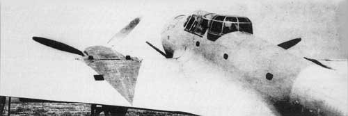
The gunner’s cockpit had a glass cover that could be raised above the fuselage, which guaranteed a shooting angle of 65º upwards, 15º downwards and 45º horizontally to the sides.
The model was capable of carrying 200 kg (2 FAB-100 or 20 AO-10 bombs). In case of elimination of the 37 mm guns, the bomb load reached 1000 kg (2 FAB-500 or 4 FAB-250).
In the descriptive memory it was explained: “ – To judge the power of this aircraft it is enough to say, for example, that only the power of the weapons installed in the nose exceeds by more than 10 times the firepower of the most powerful fighter in service with our VVS. … To date, neither in the USSR nor in foreign armies there is a combat vehicle designed for active action against large groups of tanks. “This task is solved by our aerial tank fighter (VIT).”
The reaction to this Shpitalni document was instantaneous. State funding was provided and a resolution was prepared to include the model in the experimental construction plan.
On the other hand, the basis for production in Factory No.22 was not delivered. In its place for the development of the VIT at the end of August 1936 Factory No.84 in Khimki was made available. This factory, formerly part of the civil aviation scheme, had outdated equipment and lacked qualified personnel. Under these conditions, construction work on Polikarpov ‘s two-seat anti-tank aircraft began.
Unfortunately, the idea of this type of aircraft did not find the necessary support within military circles at that time.
It is noteworthy that from its conception the VIT was conceived as a technological demonstrator designed to study construction and technological methods. On its basis, a family of seven aircraft models with different tasks would be developed, capable of sharing a large percentage of common elements. This family included:
– Fast medium bomber with capacity for 800 kg of bombs inside the fuselage;
– Dive bomber with 900 kg of bombs on external supports;
– Long-range reconnaissance aircraft with a powerful armament of 4 20 mm cannons;
– Ground attack aircraft armed with six cannons, two machine guns and 300 kg of bombs;
– Fighter for large ground targets with two K-37 guns and two ShVAK;
– Escort aircraft for heavy bombers;
– Naval aircraft with floats with torpedo boat capacity.
By the end of 1936, the plans for the SVB version (Skorostnoi Visotni Bombardirovchik or High Altitude Fast Bomber) were practically finished. The word “visotni” represented a trend of the time, but in reality the model lacked a sealed cabin and turbochargers for high-altitude operations. In practice it was simply a high-speed medium bomber.
Based on this model, the plans for the model armed with VIT-1 2M-103 cannons would be developed. It is noteworthy that the “VIT” stamp appears on most of the SVB plans, but in that same period new plans were designed for the new model.
As weapons for destroying tanks, the use of two 37 mm ShFK-37 cannons of the OKB-15 NKV (as the Shpitalni construction bureau was now called) located in the wing roots was maintained. The name of these guns comes from the acronym Shpitalnovo Fyuselyazhno-krylevaya Pushka or Shpitalni Wing and Fuselage Gun.
Polikarpov presented the design of the aircraft in two variants: multiseat gunfighter or MPI and anti-tank aircraft or VIT. On January 31, 1937 the evaluation commission reviewed the model of the MPI-1 version with two M-103 engines and on July 25, by government decision, the experimental construction plan was approved for the current year in which it was considered. the construction of two examples of the multiseat gunfighter with two M-103 960 hp engines with a maximum flight speed of 500 – 550 km at an altitude of 5000 meters.
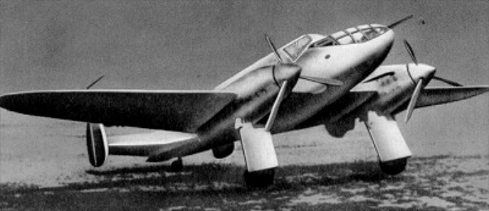
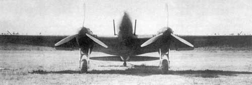
The VIT-1 was designed as a low-wing two-seat monoplane with beautiful aerodynamic shapes and smooth skin on a thin fuselage. The landing gear was of a retractable type and a monoplane tail with a single empennage.
The fuselage, built entirely of metal, had an oval cross section. The construction was semi-monocoque.
The central section constituted a combination of closed duralumin profiles and skeletal structures of welded steel tubes.
The wing, with a double spar, had a trapezoidal shape in the plane with rounded ends and ended at the junction with the fuselage, presenting the characteristic extensions of many Polikarpov models. The wing profile used was the Clark Y with a relative thickness of 14% at the root and 6.35% at the ends.
The wing spars were constructed of welded chrome-molybdenum steel tubes. The ribs were built with duralumin profiles, except for the engine area, where they were replaced by welded steel tubes. The ailerons featured aerodynamic and weight compensation.
The tail section was all metal. The stabilizer was fixed to the fuselage structure. The empennage was constructed of duralumin.
The entire cell was calculated according to resistance standards for fighters, supporting overloads of up to 13g.
The landing gear was of the conventional tailwheel type. The landers with the wheels were retracted backwards, inserting into the lower area of the power nacelles. The retraction system was pneumatic. The main wheels had brakes. The tail wheel was not retractable.
The 860 hp M-103 engines were selected as the power plant. The composition of the cooling radiators was somewhat unusual for a twin-engine aircraft. The radiators were located in retractable structures equipped with tunnels for the entry of air. These structures were located on the wing extrados on the outer sides of the power nacelles and depending on the flight regime, they extended or were practically hidden in the wing. Control was carried out with the help of a thermostat.
The VIT-1’s armament was the most powerful installed on any Soviet fighter up to that time and consisted of two 37 mm ShFK-37 cannons located in the wing roots.
The defensive armament consisted of a TUR-10 turret with a ShKAS machine gun on the rear fuselage, which would later be replaced by one of the SUDB-3 type, similar to that used in the Ilyushin DB-3 bomber, which was produced in the Factory No. 32.
The normal bomb capacity reached 600 kg on internal supports and up to 1000 kg of bombs (two FAB-500) could be installed outside.
The crew was made up of two people: pilot and gunner. Both crew members were located in a cabin on the wing spars. No shielding was provided.
On October 14, 1937, the assembly of the first flying example of the MPI-1 gunfighter was completed. The prototype was built in the Moscow factory No.84, where Polikarpov had been transferred with his team in the second half of 1936. Some time later this would begin to be called VIT-1 (Vozduzhni Isterbitiel Tankov or Aerial Tank Fighter No.1). This would be the definitive name used from now on to refer to the plane.
The first flight with Valeri Pavlovich Chkalov at the controls took place on October 31. On November 16, during the third test flight, the navigator’s cockpit would be occupied by designer Nikolai Polikarpov.
The VIT managed to reach a fairly high maximum speed for its time, of 494 km/h at 3000 meters altitude. The range recorded at 90% of maximum speed was about 1000 km.
The factory tests, carried out until February 1938, would never be completed due to the impossibility of achieving the specified performance. The plane did not manage to exceed 500 km/h and some problems related to longitudinal and transverse stability were evident.
Despite this, the model proved to have development prospects and only the lack of support from the GUAP prevented its presentation to the state acceptance tests. The VIT-1 incorporated powerful weapons for the time: two 37 mm ShFK-37 (K-37) cannons in the wings, so the VVS decided to receive the model to develop range tests, basically aimed at fine-tuning the cannons.
In these exercises, held at the weapons range near Noginski between July 13, 1938 and July 31, 1939, the guns received an excellent rating and the pilots appreciated the excellent diving qualities of the model. GF Baidukov and MM Gromov participated as pilots for the NII VVS in these tests. Unfortunately, the plane was not yet “polished” and had problems characteristic of any plane under development. On the other hand, firing both cannons in unison practically stopped the plane in flight, while firing just one of them forced the plane to turn to that side, slightly diverting the shot from the desired trajectory.
Testing was stopped after NIP AV VVS test pilot Major Anshitkov refused to continue flying the VIT-1 prototype. This was mainly due to the fact that he was a weapons test pilot and not an airplane test pilot, so flights in an unfinished airplane became especially difficult for him.
In the summer of 1937, in parallel with the military version VIT-1, the project of a civil model was developed, designed to participate in a Paris – New York competition, flying over the Atlantic. This race was scheduled for 1938, but finally it did not take place and the project was abandoned.
A total of five VIT-2 were built.
VIT-1 Powerplant: 2 x 960 hp М-103 Wingspan: 16.50 m Wing area: 40.40 m² Length: 12.70 m Height: 3.40 m Empty weight: 4013 kg Normal takeoff weight: 6453 kg Wing loading: 159 kg/m² Power load: 3.3 kg/hp Maximum speed at sea level: 450 km/h Cruising speed: 417 km/h Practical range: 1000 km Maximum climbing speed: 595 m/min Practical ceiling: 8000 m Time to 5000 m: 8.4 min Takeoff run: 390 m Landing run: 460 m Accommodation: 2 Armament: A ShVAK cannon in nose / two 37 mm cannons in wings / 1 x ShKAS machine gun in turret. Bombload: 600 kg internal / 1000 kg external.
Initial conception of the VIT tank destroyer with M-100 engines
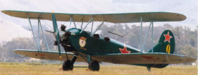
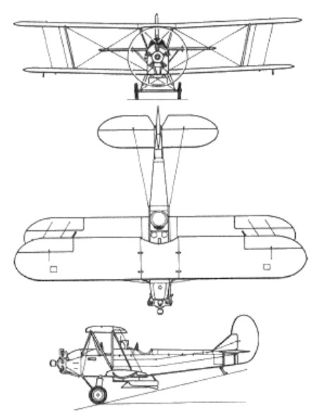
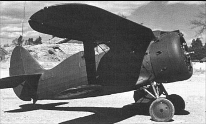
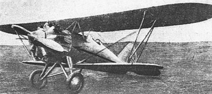
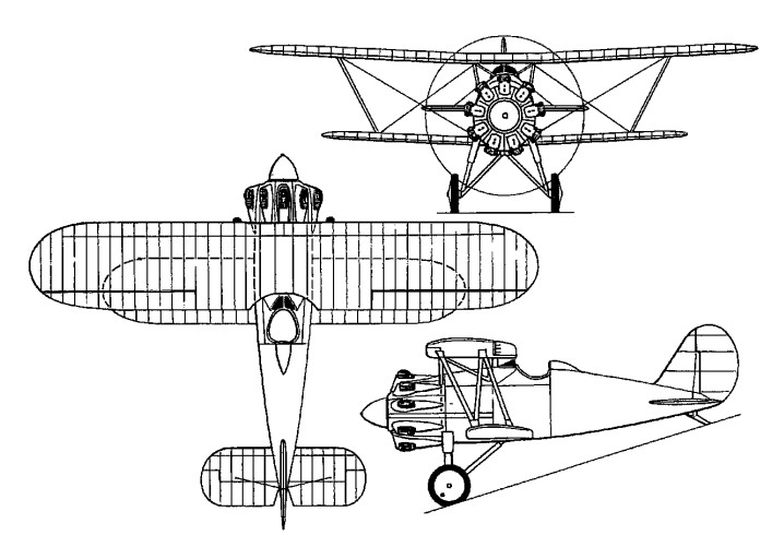
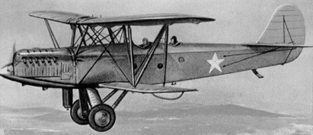
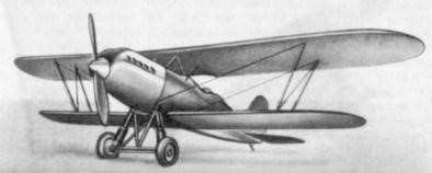
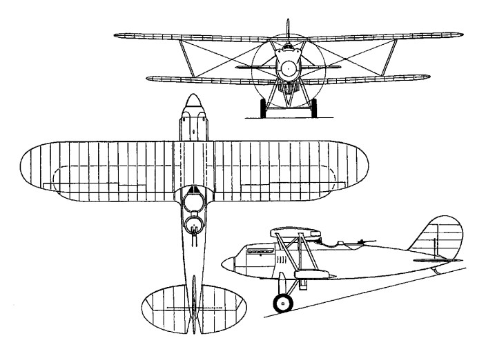
The U-2TPK prototype, which appeared in early 1927 was designed by N.N.Pellyakov, had been built to achieve economy in repair and maintenance, the wings comprising four identical thick-section interchangeable rectangular panels with square tips. Similarly, a common control surface was used for ailerons, elevators and rudder. The result was a biplane with very poor flight characteristics. It had thus to be redesigned, appearing as a neat, manoeuvrable biplane having staggered single-bay wing with rounded tips, conventional cross-axle landing gear, and tandem open cockpits for instructor and pupil. Powered by a 75kW radial engine, the new prototype made its first flight on 7 January 1928. An immediate success, it was placed in quantity production, deliveries starting in 1928, and by the time of the German invasion of the Soviet Union in mid-1941 over 13,000 had been completed.
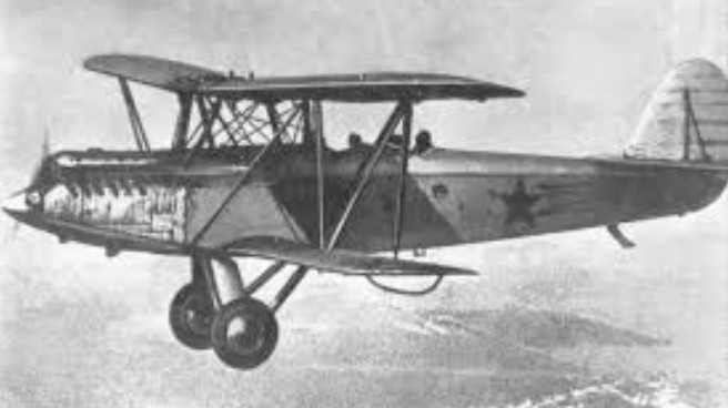
Though its principle role was primary training, the U-2 was soon modified as a light passenger transport, air ambulance and agricultural aircraft. Production continued on a massive scale during World War II, and the U-2 took on an even wider range of duties, including liaison, light attack, night nuisance raider and propaganda aircraft complete with microphone and loudspeaker.
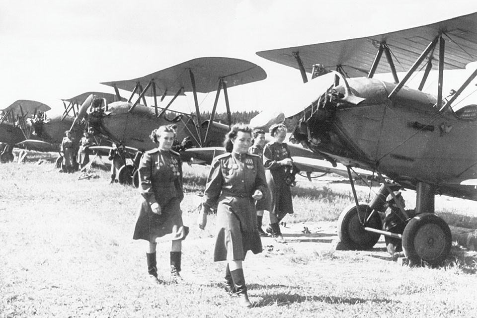
The Russians organized an entire regiment of women pilots to attack German targets at night. Called Nächthexen, or “Night Witches,” by the Germans, they operated Po-2s.
Pilots of the 588th Night Bomber Regiment, aka the “Night Witches,” in 1944
On 3 March 1944 the German 1st Easrwen Squadron ( I.Ostfliegerstaffel) was transferred to Lida airfield near Vilna (Lithuania). This unit consisted of Russian volunteers who flew captured Soviet U-3 biplanes, they called ‘sewing machines’. The unit had been set up in Daugavpils (Latvia) in December 1943, and now its members flew operations in the zone of Luftflotte 6 under General Ritter von Greim. The observers on board he U-2s dropped small-calibre bombs by hand. The aircraft flew every night when visibility permitted, crossing over the Soviet lines with nuisance raids.
In time, the Po-2 set a record for a basic design: A grand total of some 40,000 were produced. The Soviet Union built Po-2s from 1928 to 1951, and Poland turned them out under license from 1948 to 1955. But that was not the end of it. Numerous aeroclubs and enthusiasts kept constructing them in Russia until 1959.
After Polikarpov’s death, on 30 July 1944, the U-2 was redesignated Po-2 in his honour, and post-war it continued in production in the USSR for several years. Trainer and ambulance variants were built on a large scale in Poland from 1948 to 1953, Po-2s served with many Soviet allies and a small number still remain in flying condition in the USSR and several other countries. The total built is credibly reported to be in excess of 40,000.
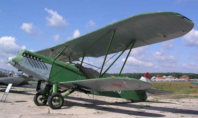
In 1947, the aviation of the People’s Army of Poland turned to the Polish aviation industry with an order to start serial production of the Soviet Po-2 training and liaison aircraft. In the USSR, it was agreed to sell its license and in 1948, the Central Aircraft Study in Warsaw, under the direction of Stanisław Lassota, the licensing documentation for the aircraft was prepared. The license version of the aircraft differed from the Po-2 prototype in a different type of ailerons, had a trim on the elevator, different shock absorber fairings and some on-board instruments, minor improvements in the airframe design, as well as an improved engine, so the designation was changed to CSS-13.
The production of the aircraft began at WSK-Mielec in December 1948. The prototype of the aircraft, SP-AKZ, made its first flight on December 18, 1948 and the pilots were Ludwik Lech and Kazimierz Tyrlik. In the following year, its testing was carried out at the Institute of Aviation in Warsaw. During the tests, it was found that the aircraft has good handling characteristics and behaved safely at take-off and landing.
In 1999, the first serial model was flown. Serial production of the aircraft lasted at PZL Mielec from 1949 to 1950, and then 1952-1956 at WSK Okęcie in Warsaw. In total, 560 CSS-13 aircraft were produced in the years 1949–1956, of which 180 at PZL Mielec and 380 at WSK Okęcie. Airplanes of this type, popularly known as “Pociaki” or “Papayas”, were used by military, agricultural aviation as well as by flying clubs.
The first new aircraft were directed to aviation units and military schools as early as 1949. In the first half of the 1950s, CSS-13 aircraft were the basic aircraft in squadrons and liaison keys of the air forces. The following versions were used: liaison equipped with a double control system, bomber with a sight glass in the lower right wing for targeting with a gunsight and bomb locks under the wing and placed on the top of the fuselage, behind the second cabin on a rack, a movable aircraft machine gun. In addition to the air force, CSS-13 aircraft were used in the aviation units of the Navy and in the Border Protection Forces to patrol the state border.
During 1953–1955, LOT Polish Airlines operated 20 CSS-13 aircraft adapted for agricultural purposes (dusting crops and forests). In the flying clubs, CSS-13 aircraft were used in the 1960s for pilot training, training flights, glider towing, and parachute jumpers transport.
CSS-13
In 1953, a prototype of the version of the CSS-13 aircraft was built and flown at the Okęcie airport in Warsaw, marked as CSS S-13, designed by Tadeusz Sołtyk, M.Sc. A total of 59 aircraft of this type were produced.
CSS-13 (serial number 8-0511), Museum of Polish Arms in Kołobrzeg
Dozens of them have been exported, e.g. to Romania and Hungary. The last copy was withdrawn from use in 1978.
A Polish-built ambulance version has a raised rear decking.
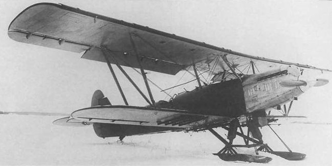
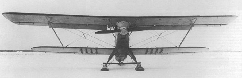
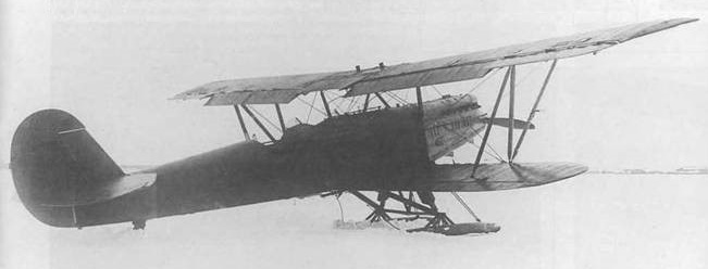
U-2: Basic model, built in large numbers as a two-seat primary trainer. It was also built in many different versions, both as civil and military aircraft. The U-2 variants also included a light transport, utility, reconnaissance and training aircraft. Power plant was the M-11 radial piston engine of 75 kW (100 hp). Later models were also equipped with uprated M-11 engines of 111 kW (150 hp). Some aircraft were fitted with a rear closed cabin, other were fitted with sledges or floats.
U-2A: Two-seat agricultural crop dusting aircraft, powered by an 86 kW (115 hp) M-11K radial piston engine. Later redesignated Po-2A after 1944.
U-2AO: Two-seat agricultural aircraft.
U-2AP: Agricultural aircraft, with a rear cab replaced with a container for 200–250 kg (441-551 lb) of chemicals. 1,235 were built in 1930–1940.
U-2G: This experimental aircraft had all the controls linked to the control column. One aircraft only.
U-2KL: Two aircraft fitted with a bulged canopy over the rear cabin.
U-2LSh: Two-seat ground-attack, close-support aircraft. The aircraft were armed with one 7.62 mm (0.30 in) ShKAS machine-gun in the rear cockpit. It could also carry up to 120 kg (265 lb) of bombs and four RS-82 rockets. Also known as the U-2VOM-1.
U-2LPL: Experimental prone-pilot research aircraft.
U-2M: This floatplane version was fitted with a large central float and two small stabilizing floats. Not built in large numbers. Also known as the MU-2.
U-2P: Floatplane version, built only in limited numbers, in several variants with different designations.
U-2S: Air ambulance version, built from 1934. It could take a physician and an injured on a stretcher on a rear fuselage, under a cover. Variant U-2S-1 from 1939 had a raised fuselage top upon the stretcher. From 1941 there were also used two containers for stretchers, that could be fitted over lower wings or two containers for two seating injured each, fitted under lower wings.
U-2SS: Air ambulance aircraft.
U-2ShS: Staff liaison version, built from 1943. It had a wider fuselage and a closed 4-place rear cab.
U-2SP: Civil transport version, could carry two passengers in open individual cabs, built from 1933. Other roles included aerial survey, and aerial photography. A total of 861 were built between 1934 and 1939.
U-2SPL: This limousine version was fitted with rear cabin for two passengers.
U-2UT: Two-seat training aircraft, powered by an 86 kW (115 hp) M-11D radial piston engine. Built in limited numbers.
U-2LNB: Somewhat like the earlier -LSh version, a Soviet Air Force two-seat night attack version, built from 1942. Armed with one 7.62 mm (0.30 in) ShKAS for rear defense, plus up to 250 kg of bombs under the wings for land support. Earlier aircraft were converted to improvised bombers from 1941.
U-2VS: Two-seat training and utility aircraft. Later redesignated Po-2VS after 1944.
U-2NAK: Two-seat night artillery observation, reconnaissance aircraft. Built from 1943.
U-3: Improved flying training model, fitted a 149 kW (200 hp) seven cylinder M-48 radial engine.
U-4: Cleaned-up version with slimmer fuselage; not built in large numbers.
(Total U-2 manufacture: 33,000)
Po-2: Postwar basic trainer variant.
Po-2A: Postwar agricultural variant.
Po-2GN: “Voice from the sky” propaganda aircraft, fitted with a loud speaker.
Po-2L: Limousine version with an enclosed passenger cabin.
Po-2P: Postwar floatplane version; built in small numbers.
Po-2S: Postwar air ambulance variant, with a closed rear cab.
Po-2S-1: Postwar ambulance version, similar to the pre-war U-2S.
Po-2S-2: Postwar ambulance version, powered by a M-11D radial piston engine.
Po-2S-3: Postwar ambulance version, which had two underwing containers, each one was designed to transport one stretcher patient. Also known as the Po-2SKF.
Po-2ShS: Staff communications aircraft, fitted with an enclosed cabin for the pilot and two or three passengers.
RV-23: This floatplane version of the U-2 was built in 1937. It was used in a number of seaplane altitude record attempts. The RV-23 was powered by a 529 kW (710 hp) Wright R-1820-F3 Cyclone radial piston engine.
CSS-13: Polish licence version, built in Poland in WSK-Okęcie and WSK-Mielec after World War II (about 500 built in 1948–1956).
CSS S-13: Polish ambulance version with a closed rear cab and cockpit and Townend ring (53 built in WSK-Okęcie in 1954–1955, 38 converted to S-13).
E-23: Research version, built in the Soviet Union in 1934, for research into inverted flight.
Engine: 1 x Schvetsov M-11, 74-118kW Max take-off weight: 983 kg / 2167 lb Empty weight: 740 kg / 1631 lb Wingspan: 11.4 m / 37 ft 5 in Length: 8.2 m / 27 ft 11 in Height: 3.1 m / 10 ft 2 in Max. speed: 146 km/h / 91 mph Cruise speed: 100-130 km/h / 62 – 81 mph Ceiling: 5000 m / 16400 ft Range w/max.payload: 430 km / 267 miles Crew: 1 Passengers: 1-2
CSS-13 Engine: M-11D, 125 hp (92 kW) Wing span: 11,4 m Wing area: 33,15 m2 Length: 8,17 m Height: 3,1 m Empty weight: 723 kg MTOW: 1057 kg Maximum speed: 150 km/h Stall: 70 kph Ceiling: 3000 m ROC: 2.0 m/s Range: 650 km Armament: 1 x 7.62 mm ShKAS machine gun Bombload: 300 kg
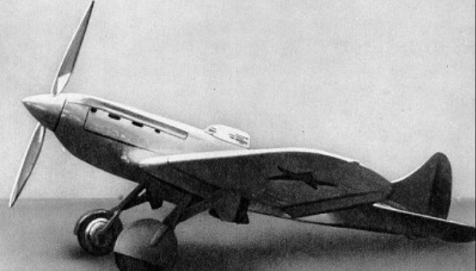
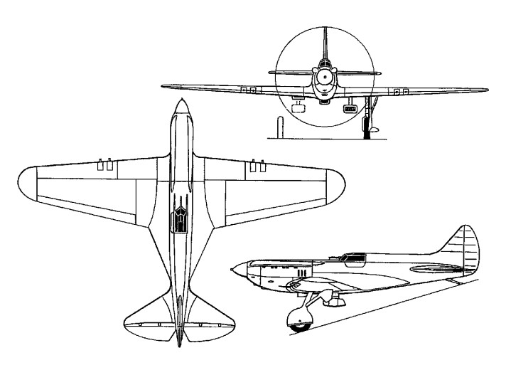
The TsKB-15 single-seat fighter prototype was a diminutive low-wing monoplane of slim configuration, powered by an imported 626kW Hispano-Suiza 12Y inline engine. With an inward-retracting undercarriage, it flew in September 1934 and was followed by the TsKB-19 with the M-100 (Soviet version of the Hispano engine). Armament comprised a 20mm cannon and four 7.62mm machine-guns. Production of a small number as the I-17-2 was reported, but it is not known if the type was used by first-line units. A third prototype (the TsKB-33) had reduced armament in an attempt to cut down weight and increase performance. The projected use of this version as a parasite fighter to be launched from a multiengined ‘mother ship’ was subsequently abandoned.
Engine: 1 x M-100, 550kW Max take-off weight: 1915 kg / 4222 lb Empty weight: 1710 kg / 3770 lb Wingspan: 10.1 m / 33 ft 2 in Length: 7.4 m / 24 ft 3 in Wing area: 17.7 sq.m / 190.52 sq ft Max. speed: 490 km/h / 304 mph Cruise speed: 440 km/h / 273 mph Ceiling: 9700 m / 31800 ft Range w/max.fuel: 800 km / 497 miles Armament: 1 x 20mm machine-guns, 4 x 7.62mm machine-guns Bomb load: 100kg of bombs Crew: 1
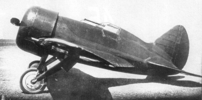
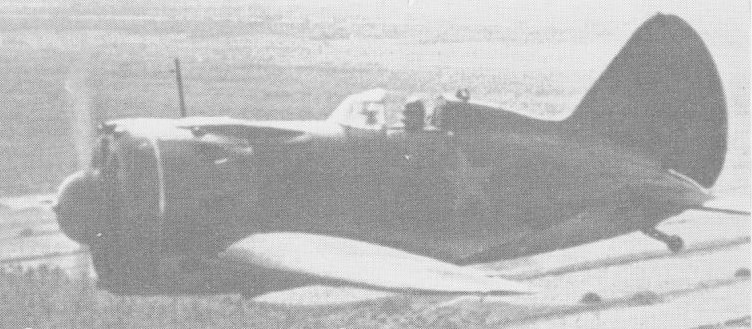
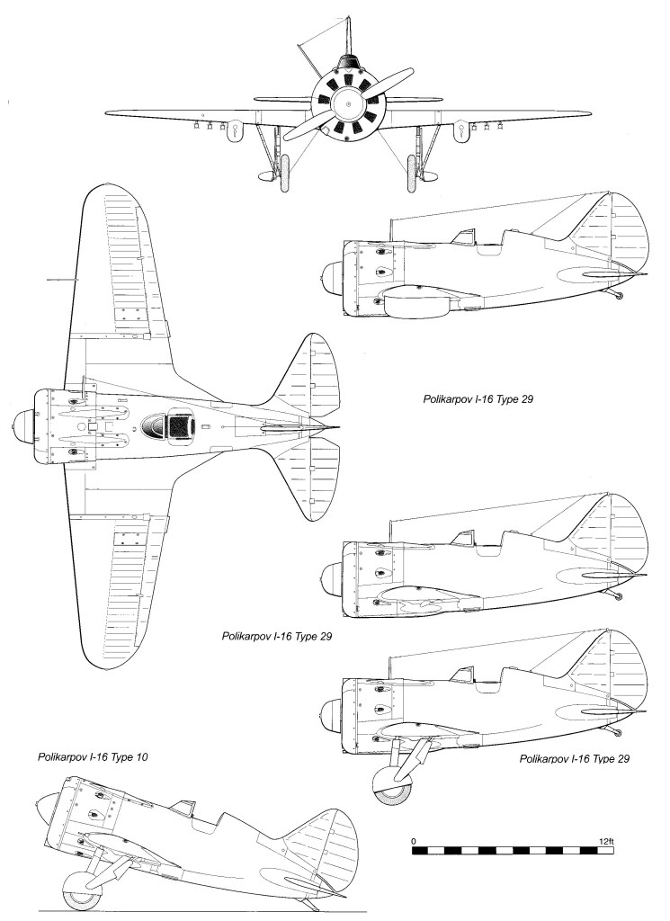
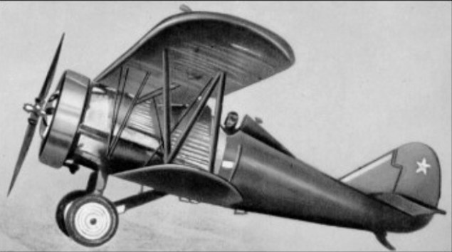
The I-16, designed by Nikolai Nikolayevich Polikarpov, externally, differed significantly from other single engined fighters of the period. It had a short fuselage with a large frontal area, wide wing panels with deep wing roots, a massive tail unit and a retractable undercarriage. Its high manoeuvrability, considered to be one of the I-16’s major advantages, primarily resulted from the aft c.g., which made the aircraft extremely unstable. This caused much trouble during flying training, but also had a positive effect.
Nikolai Polikarpov, then head of Design Team No 2 of the Central Design Bureau, developed a draft design for a monoplane fighter, initialiy designated TsKB-12, during 1932-33. Development and construction of two prototypes began in June 1933. The first prototype was powered by a 480 h.p. M-22 air-cooled radial engine, which gave it a speed of 186.5 mph at 16,400 ft. The second prototype, designated TsKB-12bis, had a 600 h.p. Wright Cyclone F-2 driving a Hamilton Standard three-bladed propeller. Both aircraft, fitted with the same NACA engine cowlings and differing only in their powerplants, had been prepared for tests by late 1933. As it was already winter, they were equipped with a fixed ski undercarriage. Although this considerably reduced flying speed, it allowed test flights to start immediately. Valery Chkalov, test pilot of Zavod (Aircraft Factory) 39, took the M-22-engined TsKB-12 for its maiden flight on December 30, 1933, and the second prototype made its maiden flight injanuary 1934. Accordingto Chkalovthe newaircraft proved to be quite difficult and unusual to fly. Both TsKB-12s were refined throughout January, and underwent most of their factory tests at that time. The State tests, aimed at determining basic flight characteristics of the TsKB-12 before a final decision was made on putting the aircraft into series production, started as early as February 1934. On February 16 test pilot Kokkinaki flew the M-22 powered aircraft, and test pilot Stepanchonok tested the machine with the Wright Cyclone.
According to the test pilots both prototypes were very responsive but demanding. They were not forgiving of any sharp control inputs, but progressed easily from one manoeuvre to another. Pilots had to be especially careful during landing, as the aircraft did not tolerate levelling off at height, and stalled immediately. However, pilots noted that the 1-16 was more stable during take-off, landing and banking, than the I-14 fighter prototype designed by the TsentrainiyAero Gidrodinamicheskiy Institut (TsAG I – Central Aero & Hydrodynamic Institute).
The comments on the I-16’s complicated piloting techniques led TsAG 1 experts to doubt whether the aircraft could be spun successfully. Their attitude towards the fighter improved only after Chkalov conducted 75 spins in March 1934, from which the aircraft recovered perfectly.
Another testimony to the I-16’s outstanding characteristics was its use by aerobatic teams, the so-called “Red Five-Aircraft Groups”. In March 1935 the first such group equipped with I-16s comprised pilots Kokkinaki, Shevchenko, Suprun, Evseyev and Preman, who trained extensively to hone their skills. A slow ascending roll of the entire group of five aircraft was their most stunning manoeuvre. Chief of the V-VS Yakov Alksnis suggested that the roll be demonstrated over Moscow’s Red Square during the military parade on May Day.
On April 30, 1935, the pilots arrived at the parade ground, where they were to fly between two buildings spaced some 130 ft apart. At Kokkinaki’s request a widewhite stripe was painted along the centre of the passage between the GUM department store and the Historical Museum for the pilots to use as a reference. This was the passage along which Soviet tank columns drove into Red Square during traditional military parades.
The following day the five bright-red I-16s descended below the rooftops, sped into Red Square in a tight formation with a deafening roar and carried out a steep climb, rolling as one.
The effect was tremendous. Having returned to their airfield the pilots were already leaving for home when Marshal Voroshilov’s aide arrived at the airfield, bringing a considerable cash bonus and promotion for each pilot. Voroshilov telephoned the airfield and told Kokkinaki: “Comrade Stalin highly appreciates the pilots’ skills and is asking them to fly over Moscow once again”.
After that, the five-aircraft group flew above the Moscow streets repeatedly. They were seen over various districts of the city, which resulted in a legend that several “red five-aircraft groups” flew over Moscow on May Day 1935.
To facilitate rapid mastery of the new fighter, pilots from aerobatic teams toured military garrisons throughout 1935. Their demonstration flights were expected to dispel any doubts ordinary pilots might have about the I-16. Later, Polikarpov and all participants in the events were decorated with Orders of Lenin, then the highest state award.
The I-16 entered series production at Zavod 39 in Moscow and Zavod 21 in Nizhny Novgorod in the Volga region. The Moscow factory dealt with every design modification and developed detailed documentation for mass production of the new fighter.
The I-16s produced there were designated in compliance with TsKB serial numbers. In 1934 the factory delivered fifty I-16s with serial numbers 123901-123950 (standing for TsKB-12, produced by Zavod 39, and finally the machine’s individual number). The Moscow factory built eight more aircraft during 1935-36 (four aircraft a year), stopping at aircraft 123958.
Although Zavod 21 started I-16 series production in 1934 it did not get up steam until the following year. The I-16 was the fourth type of aircraft manufactured by Zavod 21 after the I-5, KhAl-1 and I-14. Thus the first I-16s, powered by M-22 c, engines, were designated Type 4. The Nizhny Novgorod factory produced them throughout 1935. The total number of M-22- powered I-16s, including aircraft of the same type built in Moscow, amounted to 400. Type 4 fighters did not take part in combat operations, but they remained in service, primarily with flying schools, until 1941.
I n 1935 I-16s started to be fitted with M-25 engines, which were a Soviet copy of the Wright Cyclone F-3. Engines were produced at the new Zavod 19, built at Perm in the Urals. The factory manufactured a total of 660 M-25s during the first year of its operation. Some of the engines were expected to be mounted on I-16s. Zavod 21 designated the new M-25 powered variant the Type 5.
The 1-16 was armed with the state-of-the-art 7.62mm ShKAS machine-gun from the outset. This weapon, developed by armourers Shpitalny and Kornaritsky in 1932, had the world’s highest rate of fire, at 1,800 rounds per minute. At first the ShKAS machine-gun, launched into mass production in 1934 just like the 1-16, had a number of snags which had to be rectified in the course of operation. Although the new gun cost five times more than the mass-produced PV-1 machine gun (5,000 Roubles in 1934), it was one-and-a-half times lighter and had twice the rate of fire.
Ten I-16s manufactured by Zavod 39 in Moscow underwent service tests at the 107th Air Squadron, the Bryansk Air Brigade, from August 28 until November 3, 1935. Military pilots assessed the aircraft’s advantages and disadvantages, and every possible combat usage. They found that lowering the ailerons during take-off and landing (the ailerons of the I-16 Types 4 and 5 also acted as flaps) reduced the take-off run and landing roll considerably. This became quite a strong argument for I-16 proponents, since the work of enlarging existing airfields to accommodate new fighters had just started.
As far as piloting techniques were concerned, it was stated: “The aircraft was easy to control and very responsive to the control stick … it did not allow any mistakes … too strong a pull on the control stick during banking and landing may result in a spin stall.” Soviet feature films of the 1930s featuring the 1-16, such as Istrebiteli (Fighters) and Valery Chkalov, prove that the fighter indeed performed this aerobatic manoeuvre perfectly.
The I-16 was initially refined and improved by a team of designers in Moscow, headed by Polikarpov, in April 1936 this team developed the TsKB-12P (1-I6P), with two wing-mounted 20mm SWAK cannon and two ShKAS machine-guns.
The I-16P underwent tests frorn July to September 1936. As early as 1937 this variant, designated Type 12, was launched into series production at Nizinny Novgorod. The armament layout was modified in 1938; the cannon remained in the wing centre section, but the machine-guns were now housed in the fuselage. This I-16, powered by the supercharged M-25V engine, was designated Type 17 and put into mass production.
Another TsKB project entailed fitting the fighter with a retractable ski undercarriage. Zavod 39 in Moscow fitted an M-22-powered I-16 with such an undercarriage on February 2, 1936. Tests using aircraft Nos 123904 and 123906 proved the system satisfactory, but the matter of mass-producing such an undercarriage had never been raised, and for the following two winters military units operated I-16s with fixed ski undercarriages. The ski retraction system was improved in 1938, and from then on all seriesproduction aircraft (save for Type 29 fighters) could be fitted with skis in winter without any detriment to their flying characteristics.
After the I-16 was put into mass production at Nizhny Novgorod, all major I-16 refinements and modifications were developed there. In 1937 the factory worked on reducing the weight of certain I-16s. These aircraft, the weight of which did not usually exceed 3,2851b, were registered as “red aircraft” ‘ They were special I-16s for the “Red Five-Aircraft Groups” and were sometimes stripped of armament and even some of their equipment and instruments. It took these lightweight versions 12sec to complete a turn, compared with the usual 15-16sec. The exact number of such I-16s built is unknown, but in 1938-39 every military district had an aerobatic team equipped with them. Separate I-16s of this type took part in hostilities in 1941-42.
Zavod 21 at Nizhny Novgorod manufactured 1,881 I-16 Type 5s, Type 12s and Type 15s (UTI-4 two-seat trainers) in 1937. However, considerably improved versions, the Types 10 and 17, with M-25V engines, were put into mass production in 1938. At the same time much effort went into reinforcing the structure of earlier models. These constraints resulted in a significant drop in output, only 1,068 I-16s of all types being produced in 1938.
In early 1939 the M-25 engine was replaced by the 830 h.p. M-62, aircraft thus modified being designated I-16 Type 18.
In late 1939 Zavod 21 built aircraft powered by M-62 and M-63 engines, thus replacing machine-gun-armed Type 10 fighters with Types 18 and 24 fighters, and cannon-armed I-16s Type 17 with Type 27 and 28 respectively.
As it was the most numerous Soviet fighter, the I-16 was frequently used for testing new armament. It was fitted with bomb racks for the first time in early 1937. A fighter equipped with underwing racks designed to carry 280kg (6201b) of bombs was tested at the Nauchnolspitatelniy Institut VoyennoVozdushnykh Sil (NII V-VS Scientific Testing Institute of the Air Force) f rom February 10 to March 3,1937. It had four DER-32 racks for AO-10 bombs and a DER-3 rack for FAB-100 bombs under each wing. This modification never entered production. Later, series-production I-16s were equipped with standard bomb racks similar to those of the I-153, capable of carrying tear-shaped PSB-21 external fuel tanks or two 100kg bombs.
In 1939 I-16s were fitted with RS-82 rocket projectiles (RPs) mounted underwing, and were combattested duringthe RussoJapanese conflict in Mongolia. This version entered series production in 1940 and was later widely employed in combat.
In the summer of 1941 I-16s were equipped with two RS-132 RPs under each wing, although there is little information on the use of this weaponry.
The I-16’s operating altitude was increased by using TK-1 turbosuperchargers powered by engine exhaust gases. Experts believed that such turbosuperchargers would considerably boost the aircraft’s combat capabilities at altitudes up to 10,000m (32,800ft).
The first I-16V (Vysotniy, or high-altitude), powered by the M-25A and fitted with two TK-1 turbosuperchargers, was operational by late 1938. The Soviet Union’s first high-altitude fighter, itwas followed by several others, powered by M-25V and M-62 engines. Turbosuperchargers posed a fire risk where their exhaust plumes hit the fuselage, so the sides and the wing centre sections of such aircraft had special metal plating.
A number of successful flights were conducted in 1939. Powered by an M-25V and fitted with two TK-1s, I-16 No 1021582 reached a maximum speed of 307 m.p.h. at 28,200ft, and a maximum speed of more than 310 m.p.h. when powered by an M-62. Such aircraft did not see series production.
In the second half of the year Zavod 21 started manufacturing the latest I-16 variant, the Type 29, which incorporated work on gun armament undertaken in 1939. In addition to two synchronised ShKAS machine guns it was armed with the B1 heavy machine-gun, accornmodated between the wheel wells. The Type 29’s wings had standard mounts for six RS-82 RPs and attachment points for external fuel tanks. In total, 2,207 I-16s of the following types were produced in 1940: Type 18 and Type 24 – 760 Type 28 – 277 Type 29 – 570 Type 15(UTI-4) – 600
The last year of I-16 series production was 1940. The final variant, the Type 29, was removed from the production plan in the last quarter of the year, and in December Zavod 21 began building the Lavochkin LaGG-3 fighter under the factory designation Type 31. The last 80 Type 29 fighters and 256 UTI-4s from previous backlogs were delivered in 1941.
Zavod 153 in Novosibirsk also started building I-16s in 1937. It manufactured 27 Type 5s in 1937, 105 of the same type in 1938, and 254 (including some Type 24s) in 1939. It was decided against producing 500 I-16 Type 24s planned for 1940; the Novosibirsk factory delivered 503 UTI-4 trainers. In 1941 this plant produced 404 UTI-4s and 19 Type 24s, but late in the year it started building LaGG-3 and Yakoviev Yak-7 fighters. The last series- production I-16s – two-seat UTI-4s – were built at Zavod 458 in Rostov-on-Don from March 1941. This factory had produced 310 UTI-4s and overhauled another 146 by the outbreak of war. After evacuation to Baku in Azerbaijan it continued building them.
I-16B
At Baku the trainer was converted into a combat aircraft, designated UTI-413 (Type 15B). The wing centre section housed two non-synchronised Berezin 12.7mm heavy machine-guns, and the wings carried three RS-82 RPs per side and racks for 110 lb of bombs. The rear cockpit was covered by a duralum in fairing. This version was tested by the 480th Istrebiteiniy Aviatsionny Polk (IAP – Fighter Air Regiment) at its airfield near Kishly, and by the 266th IAP at Shekhikay, near Baku. In early 1942 it was admitted that the Type 15B was superior to other I-16 variants as far as firepower and adaptability were concerned. Moreover, standard UTI-4s could be converted into Type 15Bs. The last 83 UTI-4s were built in Baku in 1942, but it is not known whether these aircraft were armed.
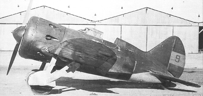
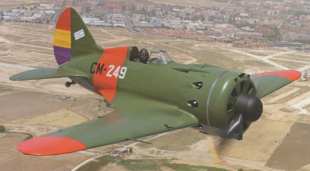
Three variants used by the Republicans were the I-16 Tip 5 with the 541-kW (725-hp) M-25, an enclosed cockpit and two machine-guns; the Tip 6 with the 544-kW (730-hp) M-25A and a strengthened airframe; and the Tip 10 with the 559-kW (750-hp) M-25V, an open cockpit and four machine-guns. Deliveries began late in 1936, and estimates for strengths (delivered and locally built) vary from 280+ to 475, while claims against it included 94 by the Nationalists, a similar number by the Germans and 242 by the Italians. The I-16 proved a good fighter in terms of performance, but was too lightly armed with just rifle-calibre guns, was an indifferent gun platform, and lacked the structural strength to deal with multiple hits from heavier guns. Some 22 aircraft fell into Nationalist hands at the end of the war, together with 90 aircraft under construction.
The I-16 was classic wood and metal design, based on the resources and capabilities of Soviet Russia’s aviation industry in the early 1930s. Its fuselage was built by covering the frame, of 11 frames, four longerons and eight stringers, with a plywood skin. The frame was of pine, ash and prima birch plywood. Areas needing reinforcement were fitted with steel struts. The skin was made by gluing together birch veneer sheets with casein glue on a special breadboard construction. Layers of veneer sheets were placed perpendicular to each other, and at an angle of 45 degrees to the aircraft’s roll axis.
The skin consisted of port and starboard halves, its maximum thickness being 5.5mm (0.2in) and its minimum thickness, in the tail, 2mrn (0.08in). Following assembly the entire wooden fuselage surface was covered with calico, puttied, and painted.
The internal fuselage surface was painted with grey oil paint during the first few years of series production, but from February 1939 it was first coated with ALG-2 primer to increase moisture resistance, and then with AE-9 grey enamel.
The wing centre section, which united the wing panels, fuselage, undercarriage and engine, was the main load-bearing unit. It comprised two trussed spars, linked and strengthened by ribs and tubular bracing struts. Its upper skin was wooden where it connected with the fuselage, and duralumin from the second rib. The upper part of the centre section had a hatch at the junction with the wing panels for access to the machine-guns or cannon. The UTI trainers and I-16 Type 29 lacked these hatches.
The lower part of the centre section had undercarriage fairings with glazed windows to enable the pilot to see whether the undercarriage was retracted.
The entire centre-section trailing edge on later I-16s was fitted with landing flaps, deflecting to a maximum angle of 60 degrees. The wing panels were similar to the centre section in design, and were connected to it by steel liners with rifled heads on the butts of tubular spars. The junction was covered by a 100mm (3.9in)-wide duralumin band. The front part of the wing was covered by a 0.6mm-thick (0.02in) duralumin skin, extending back 44.5 per cent from the leading edge on top an 14.5 percent below, and the entire wing was then covered with fabric.
At first the ailerons were fitted with a droop mechanism enabling them to act as flaps during landing, but from the Type 10 landing flaps were fitted The first series had a pneumatic flap extension, later replaced by a mechanical system.
The ailerons and tail unitwere made of duralumin and fabric covered. The fin was offset to eliminate torque. As the M-22 and M-25 (and M-62) rotated th propeller in opposite directions, the Type 4’s fin was offset 2′ to starboard, while that of followup types was offset 2′ to port.
The tailplane could be adjusted on the ground within 3′, allowin ground crew to achieve the most acceptable control column load for various c.g. positions. A removable duralumin fairing permitted easy fin adjustment. The retractable undercarriage consisted of two three-arm struts. A mechanicaljack on the starboard side of the cockpit required 44 turns to effect retraction. On aircraft of the last series the tailskid had a small 150mm (6in) tailwheel. In rainy weather pilots often fitted a tail ski, as it prevented the skid from burying itself in soft ground. Early-series I-16s had 700mm x 100mm wheels with mechanical brakes, while subsequent models had 700mm x 150mm wheels, with brake pedals mounted on the rudder bar.
The Type 10 and all subsequent variants had cotter-pins in side covers, running into the wing centre section, designed to hold the ski undercarriage retracted. These were covered with special plates in summer.
The pilot’s seat, with a pan for a parachute, initially had a light removable seat back with a soft leatherette cushion. Later it was replaced by an 8mm-thick (0.3in) 30kg (66 lb) armoured seat back. A vertical-adjustment lever on the right side of the seat provided a travel of 110mm (4.5in).
The forward -sliding windscreen had an aperture for the OP-1 gunsight, covered by a sliding panel protecting it against oil and mud and opened by the pilot immediately before openingfire.
From the Type 10, fighters were fitted with fixed Plexiglas windscreens with a stainless steel framework. The OP-1 gunsight was replaced by the PAK-1 collimator sight.
The upper part of the instrument panel, mounted on the third fuselage frame, had two round recesses for the reloading handles of the dorsal machineguns. The instrument panel stayed almost unchanged on all versions of the M 6 and was painted black. It was illuminated by two round windows inside the pilot’s windscreen in daytime, and by two cockpit hinged lamps, accommodated under the sight, at night.
The engine cowlings of I-16s powered by M-25, M-62 and M-63 engines comprised a 1,388mm (54.5in) front ring and six removable covers. The cowling was held together by hinge-rods and locks. The junction of the covers’ leading edges and the front ring was tightened by a 0.5mm-wide (0.02in) stainless-steel band.
The front part of the cowling had nine air intakes for cooling the engine. The side covers of the cowlingwere fitted with eight air outlets with ducts riveted from the inside. The exhaust pipes were connected to the same air outlets (the upper port outlet had two exhaust pipes linked to it, and the lower exhaust pipes were also coupled on aircraft fitted with retractable ski undercarriage. One of the main requirements consisted of positioning exhaust pipes flush with the cowling to reduce its sooting-up.
The propeller spinner had a diameter of 530mm (20.9in) and was fitted with a special ratchet gear for starting the engine with the help of an automobile ground-starter.
Tupolev TB-3 experiments started with two I 16 fighters, and slowly worked up to five, four of which were rolled up ramps on to cradles fixed to the bomber’s wings, while a fifth joined up in flight, hooking on to yet another version of the trapeze gear used in British and American experiments. To help get this heavy formation airborne the engines of the wing mounted fighters were run up at take off, and once up, the TB 3 could just maintain altitude under its own power.
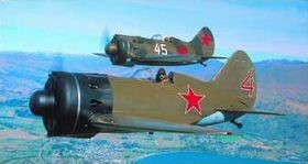
A total of 7,005 single-seat and 1,639 two-seaters were produced. Six wrecks were restored in Russia for Sir Tim Wallis and were the only flying examples in the world.
Type 4 M-22-powered first series-production I-16, with cylindrical NACA cowling. The rear edge of the cowling skirted the fuselage with a steady exit slit of about 2in, and the cowling was therefore slightly tapered
Type 5 M-25A-powered and mass-produced from mid-1935 until February 1938. Aircraft of the first series had a different engine cowling from the Type 4 and a propeller spinner. In the course of production Type 5 was gradually fitted with 700mm x 150mm wheels, a fixed windshield, and wing panels with closer rib spacing and smaller ailerons
Type 10 M-25V-powered modification of the I-16 following three years of series production. Changes included:
Two dorsal synchronised ShKAS machine-guns, mounted inside protruding fairings
Sliding canopy replaced by fixed windshield with stainlesssteel frame
OP-1 Aldis optical gunsight replaced by PAK-1 collimator gunsight
Airframe reinforced, and number of ribs on upper surface of wing increased
Ailerons reduced and aileron droop mechanism not used. Landing speed decreased with help of landing flaps. Most Type 10s fitted with pneumatic flaps. Aircraft from No 102175, produced in the spring of 1939, equipped with mechanicallyoperated landing flaps 19 Fitted with 6in oil radiator; oil cooler air intake accommodated in lower part of engine cowling
Type 12 M-25A-powered, based on Type 5, not produced in large numbers. Two wing-mounted ShKAS machine-guns augmented by two 20mm SWAK cannon
Type 14 (UTI-2) M-22-powered two-seat trainer stripped of armament
Type 15 (UTI-4) M-25A or M-25V-powered two-seat trainer stripped of armament and fitted with manual controls and extra engine controls. Undercarriage retraction jack and indicator housed in rear cockpit. M-25V-powered variants with air intakes in lower part of cowling. Undercarriage shock-absorber struts fitted with torque links. Most UTI-4s fitted with AVA propeller with locked pitch-control mechanism. From aircraft 1521109 all subsequent fighters given 35-litre wing centre-section fuel tanks. From January 1939, some UTI-4s fitted with night-flying equipment and non-retracting undercarriage
Type 17 M-25W powered modification of Type 10, armed with SWAK cannon instead of wing-mounted ShKAS machine-guns. Rounds fed from ammunition boxes inside fuselage. Hatch cut in upper fuselage for stowing ammunition belts. Upper part of engine cowling with rectangular cut-out for same purpose
Type 18 M-62-powered modification of Type 10, with more powerful engine, self-sealing fuel tank and additional 12-litre oil tank. Oil radiator mounted slightly lower, so lower part of engine cowling “sagged” slightly. Lower air intake of oil radiator enlarged. Carburettor ram-air pipe mounted on top
Type 27 M-62-powered modified Type 17; powerplant modified in similar way to Type 18 Type 24 – M-63-powered follow-on of Type 18 to comply with strength standards of 1937. It incorporated:
AVA variable-pitch propeller and new propeller spinner
Engine fitted with R-2 constant-speed unit Undercarriage shock-absorber struts with torque links. Shockabsorber travel increased to 3.8in, compared with 1.2-1.4in of previous version
Tailskid fitted with small wheel and oleo-pneumatic shock absorber
Mechanically controlled landing flaps operated by lever on port side behind pilot’s seat
Cockpit fitted with a second drop side to starboard
A manual starting system, and hatch for radio cut out of fuselage on starboard side between Frames 7 and 8.
Type 28 M-63-powered follow-on of Type 27, with same modifications as Type 24 Type 29 – Powered by M-63. 0.5in Berezin BS synchronised heavy machine-gun mounted in lower fuselage between wheel wells; no wing-mounted guns. Oil radiator moved to space between fourth and fifth engine cylinders. Undercarriage height reduced by 1.25in; wheel wells spaced further apart. Space between wheel wells covered by removable fairing. Radioequipped aircraft fitted with mast aerials mounted to starboard on engine cowling. Propeller diameter reduced to 8.85ft
1939 Production Type 10, M-25V engine – 426 Type 18, M-62 engine – 177 Type 24, M-63 engine – 155 Type 17, M-25V engine – 314 Type 27, M-62 engine – 59 Type 28, M-63 engine – 16 Type 15 (UTI-4), M-25 engine – 424 Total – 1571
Specifications
Prototype Engine: M-22 Max speed: 188 mph at 3280 ft Max speed: 175 mph at 16,400 ft Time to 16,400 ft: 10.9 min 360 deg turn: 16.5 sec
Prototype Engine: Wright Cyclone Max speed: 224 mph at 3280 ft Max speed: 195 mph at 16,400 ft Time to 16,400 ft: 7.9 min 360 deg turn: 16.5 sec
Type 4 Year: 1935 Span: 29 ft 6 in Height: 10 ft 8 in Length: 19 ft 3 in Loaded weight: 2985 lb Max speed SL: 225 mph Max speed at 9840 ft: 215 mph Landing speed: 66 mph Climb to 10,000 ft: 4.4 min Service ceiling: 24,400 ft
Type 5 Year: 1936 Span: 29 ft 6 in Height: 10 ft 8 in Length: 19 ft 8 in / 5.98m Empty weight: 2466 lb Loaded weight: 3325 lb Max speed SL: 242 mph Max speed at 8860 ft: 277 mph Landing speed: 73 mph Climb to 10,000 ft: 4 min Service ceiling: 29,855 ft Takeoff run: 720 ft
Type 10 Year: 1938 Engine: M-25V Span: 29 ft 6.5 in Height: 10 ft 8 in Length: 19 ft 11 in Empty weight: 2925 lb Loaded weight: 3783 lb / 1716 kg Max speed SL: 247 mph Max speed at 10,370 ft: 278 mph Landing speed: 78 mph Climb to 10,000 ft: 3.4 min Service ceiling: 27,780 ft Takeoff run: 850 ft
Type 12 Year: 1937 Span: 29 ft 6.5 in Height: 10 ft 8 in Length: 19 ft 8 in Empty weight: 2557 lb Loaded weight: 3788 lb Max speed SL: 244 mph Max speed at 7870 ft: 268 mph Landing speed: 80 mph Climb to 10,000 ft: 4.4 min Service ceiling: 27,000 ft Takeoff run: 900 ft
Type 15 / UTI-4 Year: 1937 Engine: M-25 Span: 29 ft 6.5 in Height: 10 ft 8 in Length: 19 ft 8 in Empty weight: 2549 lb Loaded weight: 3215 lb Max speed SL: 247 mph Max speed at 9185 ft: 280 mph Landing speed: 73 mph Climb to 10,000 ft: 3.4 min Service ceiling: 29,400 ft Takeoff run: 810 ft
Type 17 Year: 1938 Engine: M-25V Span: 29 ft 6.5 in Height: 10 ft 8 in Length: 19 ft 11 in Empty weight: 3140 lb Loaded weight: 3990 lb Max speed SL: 239 mph Max speed at 8855 ft: 264 mph Landing speed: 81 mph Climb to 10,000 ft: 4.4 min Service ceiling: 27,000 ft Takeoff run: 920 ft
Type 18 Year: 1939 Engine: M-62 Span: 29 ft 6.5 in Height: 10 ft 8 in Length: 19 ft 11 in Empty weight: 3160 lb Loaded weight: 4149 lb Max speed SL: 257 mph Max speed at 14,435 ft: 286 mph Landing speed: 82 mph Climb to 10,000 ft: 3 min Service ceiling: 30,500 ft Takeoff run: 670 ft
Type 24 Year: 1939 Engine: M-63 Span: 29 ft 6.5 in Height: 10 ft 8 in Length: 20 ft 1 in Empty weight: 3048 lb Loaded weight: 4149 lb Max speed SL: 255 mph Max speed at 15,420 ft: 287 mph Landing speed: 81 mph Climb to 10,000 ft: 3.4 min Service ceiling: 31,825 ft Takeoff run: 850 ft
Type 27 Year: 1939 Engine: M-62 Span: 29 ft 6.5 in Height: 10 ft 8 in Length: 19 ft 11 in Empty weight: 2944 lb Loaded weight: 3986 lb Landing speed: 81 mph Takeoff run: 755 ft
Type 28 Year: 1939 Engine: M-63 Span: 29 ft 6.5 in Height: 10 ft 8 in Length: 20 ft 1 in Empty weight: 3093 lb Loaded weight: 4383 lb Max speed SL: 265 mph Max speed at 6560 ft: 288 mph Landing speed: 93 mph Climb to 10,000 ft: 3.2 min Service ceiling: 32,645 ft Takeoff run: 670 ft
Type 29 Year: 1940 Span: 29 ft 6.5 in Height: 10 ft 6.5 in Length: 20 ft 1 in Empty weight: 4332 lb Loaded weight: 4227 lb Max speed SL: 260 mph Max speed at 14,700 ft: 292 mph Landing speed: 81 mph Climb to 10,000 ft: 3.3 min Service ceiling: 32,150 ft
Developed from the I-5 biplane fighter with more power, cantilever landing gear legs with faired wheels, and the upper wing gulled into the fuselage to provide the pilot with good forward and upward fields of vision, the TsKB-3 prototype flew in October 1933 with an imported 710-hp (529-kW) Wright SGR-1820-F3 Cyclone radial. The resulting I-15 Chaika (gull) entered service late in 1934 with the 480-hp (358-kW) M22 for a maximum speed of 199 mph (320 km/h) and carried an armament of two 7.62mm guns. These 404 low-performance aircraft were followed by 59 with the SGR-1820, and by 270 with the 710-hp (529-kW) M-25, a Soviet development of the Cyclone. In the meantime, armament had been doubled to four 7.62mm guns and an armoured (9mm) seat fitted.
The I-153 was first flown in May 1939 and was placed in production until the autumn of 1940 by which time 3,437 had been built, developed to incorporate retractable undercarriage and a total of 3437 were built.
The I-15 was the USSR’s standard biplane fighter of the early and mid-1930s, and from October 1936 was supplied (155) for use in the Spanish Civil War by the Republican (communist) side, which also undertook local construction (287 aircraft). Numbers are still in dispute, figures varying from 416 to 550 aircraft received or built in Spain. Spanish CASA licence-built 237 M-25-engined examples, a few of these having the M-25V engine affording 775 hp for take-off. Some 40 late-production I-15s were fitted with twin 12.7mm guns rather than the quartet of 7.62mm weapons. These figures include the basic I-15 with the 529-kW (710-hp) M-25 and two or four rifle-calibre machine-guns, the improved I-15bis (or I-152, 2,408 built) with a revised upper wing, long-chord cowling, increased fuel capacity and revised armament. At the end of the war 44 1-15 and 20 1-152 fighters fell into the hands of the Nationalists (fascists), and another 200 such fighters were found in various stages of construction.
I-152
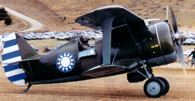
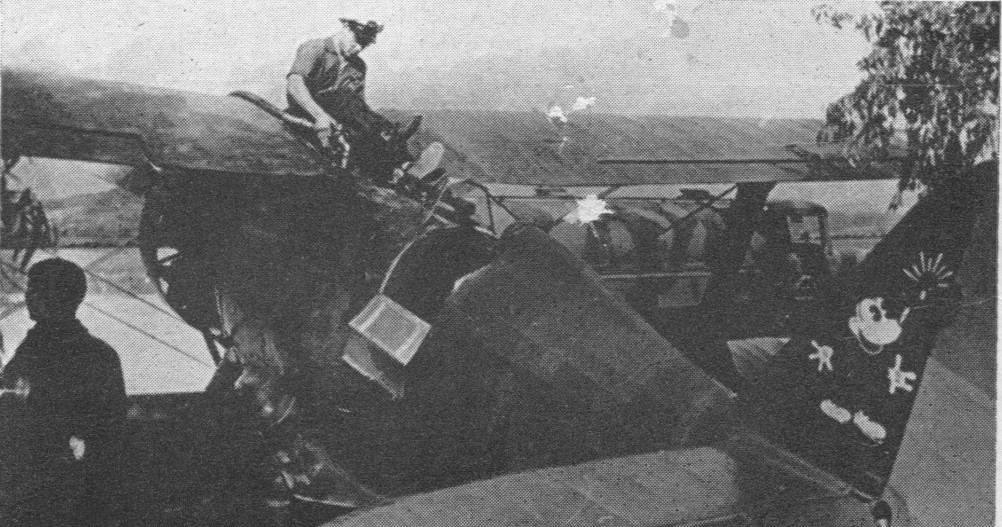
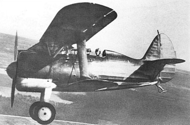
Criticism of the “gulled” upper wing centre section of the I-15, which restricted the pilot’s view for take-off and landing, led indirectly to major redesign of the fighter as the I-152 (I-15bis). The structure was restressed and extensively revised, a new Clark YH aerofoil was adopted, the span and area of the upper wing were increased, the wing centre section was carried above the fuselage by a cabane of splayed N-struts, and the 775hp M-25V engine was enclosed by a long-chord cowling. Fuel capacity was increased, but armament remained four 7.62mm guns. The I-152 was first flown early in 1937, production deliveries commencing mid-year. One of the first recipients of the I-152 was the Chinese Central Government, which was assigned 186 from late 1937 through early 1938 (an additional 86 being supplied later), and 31 reached Spain in January 1939 (a further 62 being held at the French frontier, of which 20 were subsequently released to the new Nationalist government). One example was fitted with two TK-3 turbo-superchargers as the I-152TK, one was equipped with a pressure cabin (Germeticheskaya kabina) as the I-152GK, and another was tested with DM-2 ramjets as the I-152DM. Production of the I-152 was phased out early in 1939, having totalled 2,408 examples, 60 squadrons being equipped with this type during 1939.
Despite an international trend away from the biplane configuration for fighters by the mid ‘thirties, the Soviet Air Force vigorously demanded continuation of such warplanes, and, in 1937, one of Polikarpov’s principal team leaders, Aleksei Ya Shcherbakov, was assigned the task of developing a more potent fighter biplane. Assisted by Mikhail Gurevich, Shcherbakov created the I-153 (I-15ter), prototype trials commencing in summer 1938. The basic structure of the I-152 was extensively restressed, the Clark YH wing profile was retained, but configuration reverted to the “gulled” upper wing – resulting in the sobriquet of Chaika being resurrected – and, as a concession to modernity, manually-retractable main undercarriage members were introduced. Initially, the 775hp M-25V engine was retained, armament remaining four 7.62mm guns, but comparatively early in the production run the 1,000hp Shvetsov M-62 engine was standardised, boosting max speed from 415km/h at 3000m to 444km/h at 4600m. Some aircraft were fitted with a quartet of 12.7mm guns (I-153BS) and one, experimentally, with twin synchronised 20mm cannon (I-153P). Production deliveries began during the early spring of 1939, and continued until late 1940, 3,437 examples being produced. Ninety-three were supplied to the Chinese Central Government early in 1940, and the I-153 remained in first-line service until well into 1943.
I-153
It is significant that during the late 1930s the Polikarpov I 16, the first modern fighter with cantilever monoplane wing and retractable landing gear, and I-type interplane struts, was cut back in production in favour of new versions of the Polikarpov I 15, which was a biplane.
The type served against the Japanese Army Air arm on the Manchurian border in 1939 and in the 1939-40 Winter War against Finland. More than 1,000 aircraft were still in service at the time of the German invasion of the USSR in July 1941, and these obsolete aircraft fought on into early 1942.
TsKB-3 Engine: Wright SGR-1820-F-3 Cyclone, 715hp at 2130m
I-15 Engine: 1 x M-25B, 550kW Max take-off weight: 1700 kg / 3748 lb Empty weight: 1310 kg / 2888 lb Wingspan: 10.2 m / 33 ft 6 in Length: 6.3 m / 21 ft 8 in Max. speed: 370 km/h / 230 mph Cruise speed: 290 km/h / 180 mph Ceiling: 9000 m / 29550 ft Range w/max.fuel: 600 km / 373 miles Armament: 4 x 7.62mm machine-guns Crew: 1
I-l5bis / I-152 Engine: one 775-hp (578-kW) M-25V radial Maximum speed 230 mph (370 kph) Climb to 3,280 ft (1,000 m) in 1 minute 0 seconds Service ceiling 31,170 ft (9,500 m) Range 329 miles (530 km) Empty weight 2,910 lb (1,320 kg) Maximum take-off weight 4,189 lb (1,900 kg) Wing span 33 ft 5.5 in (10.20 m) Length 20 ft 6.75 in (6.27 m) Height 7 ft 2.25 in (2.19 m) Wing area 242.52 sq ft (22.53 sq.m) Armament: four 7.62-mm (0.3-in) machine guns Bombload: 331 lb (150 kg) of bombs or six 82-mm (3.2-in) rockets Seats 1
I-l53 Engine: one 1000-hp Shvetsov M-62R radial Length: 6.17 m / 20 ft 3 in Height: 2.80 m / 9 ft 2 in Wing area: 22.14 sq.m / 238.31 sq ft Max take-off weight: 2110 kg / 4652 lb Empty weight: 1452 kg / 3201 lb Wingspan: 10.00 m / 33 ft 10 in Max. speed: 444 km/h / 276 mph Range: 470 km / 292 miles Seats: 1
With acceptance of the I-3 for series production, Polikarpov and his team commenced work on a smaller, lighter fighter, the I-6, powered by a 450hp Gnome- Rhone Jupiter VI air-cooled radial.
A single-bay, unequal- span biplane of wooden construction with fabric skinned wings and a monocoque fuselage, the I-6 was flown on 30 March 1930, two prototypes appearing in the annual May Day fly-past over Moscow in that year. Prior to the commencement of flight testing, Polikarpov had been arrested (in September 1929), accused of “exercising insufficient energy in bringing assigned work to fruition”, and, together with Dmitri P Grigorovich, was already working whilst in detention on a further fighter (the I-5). Comparative trials were subsequently performed between the I-6 and the I-5, the latter being selected for series manufacture after prolonged evaluation. The I-6 was the faster in level flight, but offered a poorer rate of climb and was less manoeuvrable. Development was therefore discontinued in favour of the I-5.
Max take-off weight: 1280 kg / 2822 lb Empty weight: 868 kg / 1914 lb Wingspan: 9.70 m / 32 ft 10 in Length: 6.78 m / 22 ft 3 in Wing area: 20.50 sq.m / 220.66 sq ft Max. speed: 280 km/h / 174 mph Range: 700 km / 435 miles
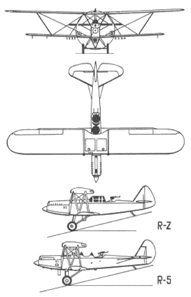
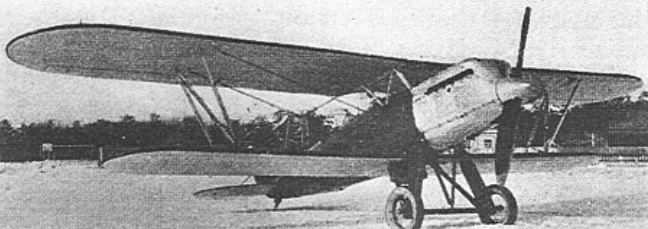
The Polikarpov R-Z or R-Zet was developed at the aircraft factory GAZ No 1 (State Aircraft Factory No 1) at Moscow as a development of, and a replacement for the Polikarpov R-5, the standard light reconnaissance bomber of the Soviet Air Force. Based on the R-5SSS, the most advanced variant of the R-5, the R-Z had a new, deeper, monocoque fuselage, with a sliding canopy for the pilot and fixed glazed fairing for the observer. Smaller than the R-5, with a more powerful engine driving a two-bladed fixed-pitch propeller. Construction however was lighter than of the R-5. The 544 kW (730 hp) M-17F engine (a licenced built copy of the BMW VI was replaced with the 611 kW (820 hp) M-34 engine. The R-Z first flew in January 1935 and was accepted for the Soviet Air Force in preference to the competing Kochyerigin LR, also an R-5 derivative. By the time production finished in spring 1937, 1,031 R-Zs had been built.
Like its predecessor the R-5, the R-Z was used in large numbers by both the Soviet Air Force and Aeroflot.
Its first use in combat was during the Spanish Civil War from 1937. 61 R-Zs were delivered to the Spanish Republican Air Force, where they were nicknamed Natacha. These were heavily used, flying in tight formations and using co-ordinated defensive fire to defend against fighter attack, while returning individually at low levels. Although many R-Zs were damaged by ground fire, complete losses were relatively low with 36 surviving to be captured by the Nationalists at the end of the war in April 1939.
R-Zs were used by the Soviet air force against Japan above Mongolia in the Battle of Khalkhin Gol in 1939, and the Winter War against Finland in the same year. By the time of the German invasion of the Soviet Union in June 1941, the R-Z was in the process of being replaced by the Ilyushin Il-2, although it remained in service with a number of light bomber regiments.
An unequal-span two-seat biplane constructed largely of wood with fabric covering, the R-5 reconnaissance light bomber flew in prototype form in 1928. Pilot and observer/gunner were seated close together in tandem open cockpits – the pilot beneath a cutout in the upper wing trailing-edge. The BMW VIb in-line engine of the prototype was replaced by the 507kW Soviet-built M-17B in production aircraft. The R-5 could operate on skis or twin-floats (the latter designated R-5A or MR-5), as well as on the more normal axle-type fixed undercarriage. Standard armament was a fixed 7.62mm PV-1 machine-gun and a DA-1 weapon of the same calibre operated by the observer. Up to 250kg of bombs could be carried on underwing racks.
Many variants of the R-5 were used in the Soviet Union. These included the single-seat R-5T torpedo bomber; the heavily armed R-5Sh ground-attack aircraft; and the SSS of 1934 with 533kW M-17F engine, spatted landing gear and new ShKAS machine-guns. Civil versions were the P-5 and P-5A, the latter with cabin accommodation for four passengers, and an enclosed pilot’s cockpit.
Some 7,000 of all versions of the R-5 were built. Military operations included the Spanish Civil War (31 R-5s serving with the Republicans), the campaigns in 1938-39 against the Japanese in the Far East, the ‘Winter War’ against Finland, and the fighting against Germany from 1941. At the time of the German invasion most R-5s had been relegated to training and liaison duties, but several hundred returned to first-line duties to equip light night-bombing ‘nuisance raid’ units alongside the Polikarpov U-2.
As early as 1930, the possibility of equipping the R-5 with a wing equipped with leading edge flaps and slats was considered. It was appreciated that an aircraft with this wing configuration would be much safer to perform the role of a night bomber.
R-5 # 4681 with leading edge slats and top plane flap
Originally the development of this variant was assigned to the TsKB-39 and later transferred to the TsKB. The modifications were made by a group under the leadership of LI Sutigun in S A. Kochierigin’s brigade. The upper wing received straight ends, trailing edge flaps following the ailerons, and slats on the wing leading edge. Two examples were modified in 1933 as Polikarpov R-5 with sectioned wing (Russian: Поликарпов Р-5 с разрезным крылом). The first, with serial number No.4681 was called Sectioned Wing – 1 and the second with number No.5563 Sectioned Wing – 2.
R-5 No.4681
During the tests it was possible to reduce the landing speed to 70 km / h. The ceiling increased and the maximum speed decreased slightly.
Despite the results obtained, the series production of the model was not approved as it was considered that the take-off and landing characteristics of the R-5 were not bad and the wing mechanization complicated the production process.
R-5 No.4681 on February 9, 1933 with slightly low flaps.
In 1933 R-5 No.4681 was used to test the VAP containers for chemical weapons developed by engineer Vaxmistrov.
Variation: Grokhovsky G-61 Polikarpov ARK-5
Engine: 1 x M-17, 370kW Max take-off weight: 3351 kg / 7388 lb Empty weight: 2108 kg / 4647 lb Wingspan: 15.5-12.0 m / 51 ft 10 in – 39 ft 4 in Length: 10.6 m / 35 ft 9 in Height: 3.6 m / 12 ft 10 in Wing area: 50.2 sq.m / 540.35 sq ft Max. speed: 230 km/h / 143 mph Ceiling: 6150 m / 20200 ft Range w/max.fuel: 600 km / 373 miles Armament: 3 machine-guns, 250kg of bombs Crew: 2
Kochierigin R-5 Engine: 1 M-17B 500/680 hp Wingspan upper: 15.50 m Wingspan lower: 12.0 m Length: 10.65 m Wing area: 50.84 m² Empty weight: 2085 kg Normal takeoff weight: 2985 kg Wing loading: 58.7 kg / m² Power load: 5.9kg / hp Fuel weight: 427 kg Total load capacity: 900 kg Maximum speed at sea level: 205 km / h Maximum speed at 3000 m: 189 km / h Landing speed: 70 km / h Practical range: 800 km Endurance: 4.5h Climb to 1000 m: 7.5 min Climb to 2000 m: 15.0 min Practical ceiling: 5140 m Landing run: 120 m Seats: 2 Armament: A 7.62mm PV-1 synchronized machine gun/ 2 x 7.62mm DA machine guns in rear cockpit.
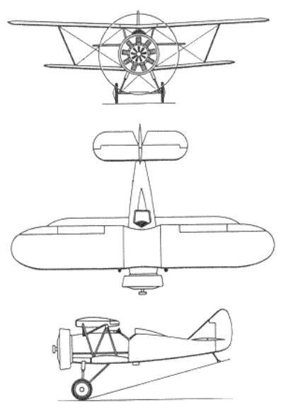
The first prototype of this diminutive single-seat unequal-span biplane flew on 29 April 1930. Power was provided by an imported Gnome-Rhone Jupiter VII radial engine with individual helmet-type fairings over each cylinder head. The second prototype was named Klim Voroshilov after the Soviet Defence-Minister. It had a Jupiter VI radial and was intended for low-level operations. The third and final prototype had a Soviet M-15 radial engine with a ring cowling. In the summer of 1930 seven evaluation aircraft were built, powered by the 358kW M-22 radial – in fact a Russian version of the Jupiter VI. Tests were successful and series production was undertaken. A total of 803 was built and the type formed the main equipment of Soviet fighter units until 1936.
Standard armament of the I-5 was two synchronised 7.62mm PV-1 machine-guns and up to 40kg of bombs could be carried on underwing racks. The circular-section fuselage had a metal tubular framework with metal sheet covering forward and fabric aft. The wooden wings were fabric covered. The axle-type undercarriage could be fitted with wheel spats.
A number of I-5s were still in use at the time of the German invasion of the Soviet Union in June 1941, when a few were pressed into service by Black Sea naval airmen for ground attack. Interestingly, I-5s had previously been used in Soviet Zveno ‘parasite’ experiments, being launched in the air from the TB-3 mother ship.
Engine: 1 x M-22, 355kW Max take-off weight: 1355 kg / 2987 lb Empty weight: 943 kg / 2079 lb Wingspan: 10.2/7.4 m / 33 ft 6 in / 24 ft 3 in Length: 6.8 m / 22 ft 4 in Wing area: 21.3 sq.m / 229.27 sq ft Max. speed: 278 km/h / 173 mph Cruise speed: 250 km/h / 155 mph Ceiling: 7300 m / 23950 ft Range w/max.fuel: 660 km / 410 miles Armament: 2 x 7.62mm machine-guns Crew: 1
Polikarpov D-2 (DI-2) two-seat fighter in its original version.
Despite the failure of the 2I-N1 fighter, the VVS was not willing to give up having a two-seat fighter. In 1927 it was decided to obtain a model from the I-3 single-seat fighter, which was successfully mass produced.
Nikolai Polikarpov considered it more important to work on the creation of the I-5 single-seat fighter with an air-cooled engine and expressed his opinion at the meeting of the Aviotrust technical committee, held on August 12, 1927. Despite his opinion, the development of the I-5 fighter with a 480 hp Gnôme-Rhöne Jupiter engine was entrusted to TsAGI and the OSS collective, under the direction of Polikarpov, received the task of creating the D-2 or DI-2 (Russian: Поликарпов Д-2 (ДИ-2)) two-seat fighter. with 500 hp BMW VI engine.
Constructively, the DI-2 two-seat fighter repeated the layout and characteristics of the I-3 single-seat fighter.
The construction was mixed. The fuselage was presented as a monocoque wooden structure. The structure was made up of 4 stringers, 4 stringers and 13 frames. The stringers were constructed from rectangular pieces of pine wood. Towards the tail section the sectional area of these spars decreased.
The construction of the fuselage at Factory No.25 was carried out in two halves. On a mold with the appropriate shape, the coating began with sheets of birch bark in several layers, fixed with the use of glue. In the bow area, 5 layers were used and only four in the tail area. Between each application of a layer, the previous one was left to dry for 6 – 7 hours. Once the gluing process was completed, the entire structure was left to dry for 10 – 12 days.
The two halves were located on the wooden structure, fixed with screws and nails. In the joining area, a 50 mm wooden strip was placed, which was glued and also fixed with screws. The fuselage, once completed, was painted with two layers of enamel and the bow area was protected by sheets of duralumin.
The engine cowling was fixed to the structure, in the same way as the upper part of the fuselage located from the machine gun position to the windshield of the pilot’s position. Behind the gunner’s position the fuselage continued with a duralumin upper fairing, which could be removed and to which the rudder control cables were attached.
The wing box was made up of planes of different spans joined by N-shaped supports made of aluminum tubes. These supports were fixed to the wing using screws, which also served to adjust the wing. The upper and lower planes had a Clark Y profile and a double wooden spar structure with plywood covering from the leading edge to the first spar. The upper plane featured ailerons constructed from a fabric-covered duralumin structure. To attach the ailerons, the upper plane had a third additional spar.
The upper center plane in its front part had two tanks intended to store water and fuel. The fuel tank, with a capacity of only 2.5 liters, was used to start the engine, reaching the engine by gravity. The second, slightly larger tank was part of the engine cooling system. This system was composed of a retractable honeycomb radiator. The retraction system was operated from the cockpit using a crank located on the left side of the cockpit.
The tail unit featured aluminum construction. The keel was made of wood and was incorporated into the structure of the plane. To facilitate flight control in different regimes, the stabilizer could vary its deployment angle. This angle could be modified by the pilot in flight using a lever located on the right side of the cockpit.
The landing gear was of the conventional type with a tail skid. The main landers featured a steel skeletal structure with duralumin fairings with a central flat piece within which the rubber shock absorbers were located. The half-axles of the wheels in the central area were joined by a common axle. To guarantee greater rigidity, support arms were used. The spoked wheels had dimensions of 800 x 150 mm. It is noteworthy that in many cases the spokes were covered by duralumin discs to improve rigidity. The tail skid was made of duralumin and had cushioning using a rubber strip. Its operation was synchronized with the position of the rudder.
In winter the wheels were replaced by ash skis similar to those used by the R-1.
The D-2 was equipped with the BMW VI liquid-cooled engine with a nominal power of 500 hp and a maximum calculated between 680 and 730 hp. This engine was considered high altitude, prepared to obtain its highest performance at altitudes of 2500 – 2700 m.
The fuel system, apart from the small tank on the upper plane, consisted of a tank located in the fuselage. The engine was powered by AM type fuel pumps that were driven by the engine itself.
The engine was started by using a 5 liter cylinder of compressed air. In case of failures, an emergency starting system was used.
The cockpit equipment was quite standard for a fighter of the time. Of note is the use of a large AP compass located under the instrument panel, between the pilot’s legs.
The D-2’s armament consisted of a pair of synchronized PV-1 machine guns firing through the propeller and one or two PV-1 machine guns in a ring mount located in the gunner’s cockpit. For aiming, the pilot used an OP-1 type collimator located in the center of the windshield. As additional support, a KP-5 annular mechanical collimator was located on the right side of the fuselage and near the windshield.
The technical task for the construction of the two-seat fighter was modified several times. In 1928 Polikarpov received the task of designing the ND-2 night fighter and the builder himself presented a version with a 480 hp Gnôme-Rhöne Jupiter radial engine. However, these “deviations” were discarded and finally the D-2 was built from the original specifications.
The BMW VI- powered D-2 prototype was built at Factory No.25 in the spring of 1929.
D-2 two-seat fighter in original version
Factory tests began on March 15 and lasted until July 1929. The plane was flown by test pilot BL Buxgolts and in his opinion the plane showed no disadvantages of any kind in relation to most fighters of the time. With the installation of more powerful weapons, this fighter could be more effective than single-seat fighters.
On the other hand, Buxgolts highlighted that the D-2 had a centering that was too late, which affected the characteristics of the plane in a spin.
After the development of the tests, the plane remained abandoned for a long time, almost a year, due to the lack of requests for the continuation of the work. By this time Polikarpov was arrested and Factory No.25 was absorbed by Factory No.39.
In the spring of 1930 work on the D-2 fighter was continued. In order to improve the behavior in spin, the tail unit was modified by adding V planes located with an inclination of 8º with respect to the horizontal. This type of tail was used for the first time in the USSR).
Other modifications included the addition of a TUR-7 turret to the rear gunner position. This new installation was simply a TUR-6 ring mount with the ring diameter reduced from 710 to 636 mm. Two paired Lewis machine guns were originally installed there, but later a single Degtiariov light machine gun for aircraft was located there.
On June 13, 1930, the first flight was made with the new V-tail unit. Kozlov was appointed as test pilot. The following days were dedicated to making certain adjustments and the aircraft was transferred to the NII VVS to begin state testing.
In the NII VVS the D-2 was flown by Buxgolts, Zhukov and Pisarienko. None of these pilots in their reports stated anything in relation to the new tail unit. Only Buxgolts describes that he failed to notice any improvement in the plane’s behavior.
The general assessment was positive, considering that the D-2 was overall a good combat aircraft. A request was made to develop a small batch in series, mainly motivated by the need for VVS in two-seat fighters.
At the end of July 1930, pilot Vladimir Ivanovich Chekariov joined the D-2 tests. By that time, a total of 6 hours and 48 minutes of flight had been reached.
On August 4, 1930, Chekariov received the task of testing the control of the D-2 at altitudes of 3000 m, but the first flight of the day, carried out together with the observer Vasily Ivanovich Blagonadiezhni, was intended to measure the maximum ceiling of the plane. Equipped with oxygen cylinders and masks, the pilots soared until they reached a height of 7,170 meters and landed happily.
After a rest they began to prepare to make the second flight. Responsible for the flights that day was the head of the first brigade of the fighter department of the NII VVS Nikolai Alexeyevich Zhemchuzhin. According to his words, the pilot Chekariov, when heading to the second flight, said: “Now I will tame him as he should. ”
The pilot was referring to pushing the plane with maximum overloads. Zhemchuzhin snapped: “Stop this nonsense, this is not the VT” (he was referring to the VT-11 or I-5, flown by Chekariov).
Among the ground observers were the renowned builder and assistant to the head of the TsKB-39 D. P. Grigorovich and the deputy head of the TsKB I.M. Artamonov. According to their statements, after executing its task the plane came out of the clouds at a height of 1,200 m and then began to descend in a spiral to about 100 m. Observers noted a strong vibration in the tail, which would soon be accompanied by the destruction of the right section of the stabilizer. This caused the destruction of the wing box and the plane hit the ground. The crew died instantly. Despite having both parachutes, it was impossible for them to leave the plane due to the low altitude.
Investigations showed that the vibration in the tail had been noticed before, but none of the testers had given it importance. It was considered that when the tail was raised, the upper wing exerted an important influence on its operation, which caused these vibrations.
It was considered that the rough handling of the plane resulted in damage to the attachment points and the vibration accelerated the process, which ended in the destruction of the tail.
With the loss of the D-2 the small batch approved for production was cancelled. The accident contributed to worsening the position of the detained Polikarpov and his specialists.
Despite the loss of the D-2 prototype, work on the development of two-seat fighters did not stop. Following VVS requirements, the development of a combat and reconnaissance version with a BMW VI engine began , whose model was presented for evaluation on October 8 , 1930 . This project would never be finished because the DI-3 would soon appear, created in the OGPU system and in which great hopes were placed.
Powerplant: 1 x 730 hp BMW VI Wingspan: 11.80 m / 39 ft 9 in Wing area: 31.80 sq.m / 342.29 sq ft Length: 8.20 m / 27 ft 11 in Height: 3.12m Max take-off weight: 2122 kg / 4678 lb Empty weight: 1557 kg / 3433 lb Fuel capacity: 210 kg Lubricant capacity: 33 kg Total load capacity: 565 kg Wing loading: 67.0 kg/m² Power load: 2.9 kg/hp Max. speed: 256 km/h / 159 mph at SL Speed at 5000 m: 243 km/h Landing speed: 100 km/h Cruising speed: 231 km/h ROC: 455 m/min Range: 510 km / 317 miles Endurance: 2 hours Service ceiling: 6,300 m Spin time: 14s Time to 1000 m: 2.2 min Time to 2000 m: 4.5 min Time to 3000 m: 7.2 min Time to 5000 m: 17.5 min Landing run: 250 m Takeoff run: 180 m Armament: 4 x 7.62 mm PV-1 machine guns Accommodation: 2