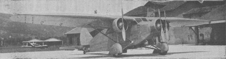
In 1930 the Direection Générale Technique issued a programme for an aircraft to operate in the French Colonies. It was to have three Lorraine 9N Algol engines and an all-metal structure, capable of reconnaissance, observation, policing and bombing as well as medical evacuations or general transport. The Romano R.16 was one of nine prototypes built to this programme.
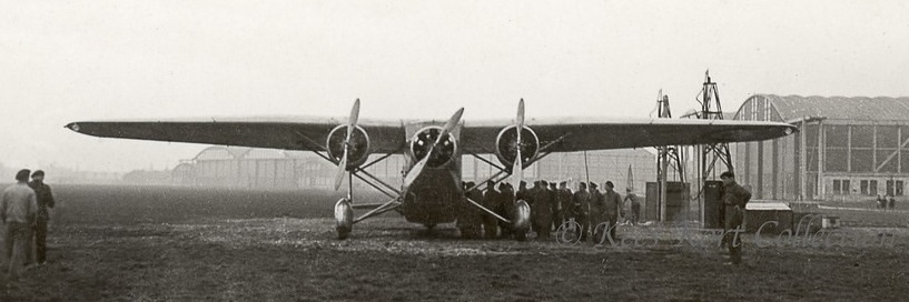
Despite the all-metal requirement, the Romano R16 initially flew with a wing of mixed construction which was originally built for the rather similar Romano R.6 civil passenger aircraft. It is not known if the intended wing, all-metal and expected to be lighter, ever replaced it. On each side the high wing was in two parts, with a rectangular inner section attached to the top of the fuselage. The outer panels were straight tapered to rounded tips. The wing had two wooden box spars and spruce ribs and was entirely plywood covered. The centre section, over 40% of the span, was braced at its outer ends with a pair of parallel steel wing struts between the wing spars and the lower fuselage longerons, so that the R.16’s wing was a semi-cantilever one. High aspect ratio ailerons occupied the whole outer panel trailing edge and camber changing flaps filled those of the centre section.
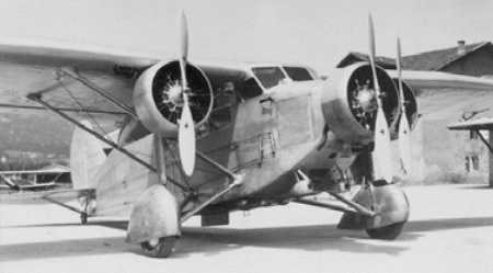
The R.16 was powered by three 220 kW (300 hp) Lorraine 9N Algol nine cylinder radial engines enclosed by long chord NACA-type cowlings. One was in the nose of the fuselage and the other were mounted under the wing centre section from the forward wing struts, aided by bracing struts rising inwards to the wing root and short vertical struts to the forward spar. Long nacelles behind the outer engines tapered to the rear wing strut.
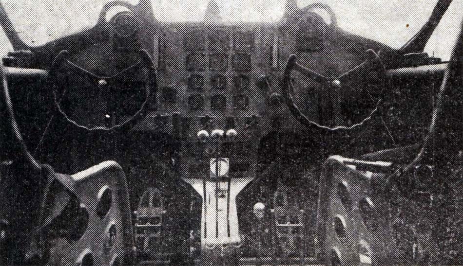
Structurally the R.16’s fuselage was built around steel tube longerons, giving it a simple rectangular cross-section. The pilots’ enclosed cabin was below and just ahead of the wing leading edge, fitted with side-by-side seating and dual controls. Behind them there was a generous cabin, accessed via a large port side door. Aft of the cabin, just behind the trailing edge was a dorsal gunner’s position. At the rear the fixed surfaces were approximately triangular and carried a balanced rudder and elevators, also balanced. Each tailplane was braced on the vertex of a V-strut from the lower fuselage. The tail surfaces were steel tube structures with fabric covering.
The colonial aircraft were expected to have to use basic or unprepared strips, so needed a robust undercarriage. The R.16 had large 1,150 mm (45 in) diameter wheels, independently mounted and fitted with brakes that could be use for steering, enclosed under large fairings. Each wheel was on a cranked steel half axle from the lower fuselage with a trailing recoil strut and a vertical oleo leg to the engine mounting.
The R.16 flew for the first time in February 1933. By May the initial development tests at Romano’s Cannes factory were complete. It then went to Villacoublay for its official tests, which were completed by early September.
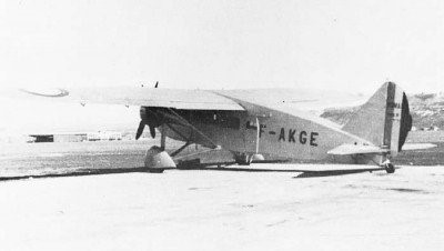
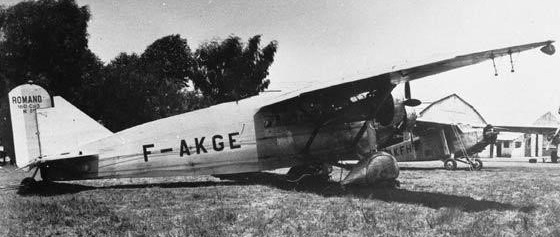
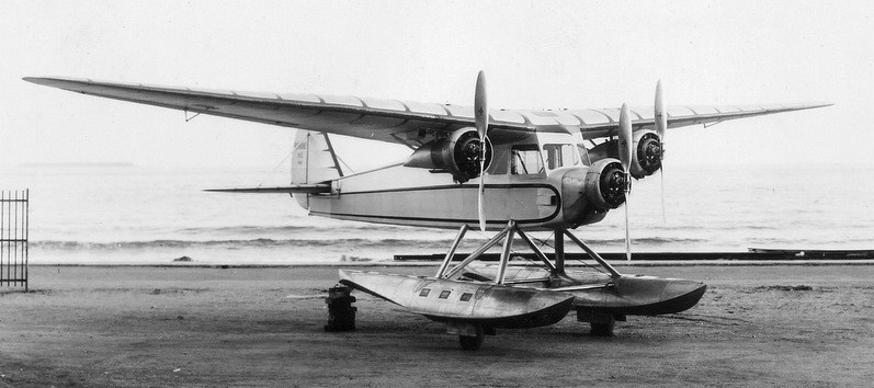
The Colonial trimotor contract was awarded to the Bloch MB.120, so no more R.16s were built. The sole example appeared in the prototypes section of the French civil aircraft register as F-AKGE, with the type name Romano 160 and was used by the Commander of the 5th Aerial Region of French North Africa as his personal transport. A photograph taken at Cannes in 1937 shows that by then it had been adapted to carry passengers, the cabin now lit by long, continuous windows on each side. It also had a revised vertical tail with an unbalanced rudder.
Romano R.16 Powerplant: 3 × Lorraine 9Na Algol, 220 kW (300 hp) each Propellers: 2-bladed Ratier Wingspan: 21.60 m (70 ft 10 in) Wing area: 70 m2 (750 sq ft) Length: 13.90 m (45 ft 7 in) Height: 4.05 m (13 ft 3 in) Empty weight: 3,138 kg (6,918 lb) Gross weight: 5,200 kg (11,464 lb) Fuel capacity: 415 l (91 imp gal; 110 US gal) Maximum speed: 230 km/h (140 mph, 120 kn) at ground level Cruising speed: 195 km / h Landing speed: 81 km/h (50 mph; 44 kn) Range: 1,200 km (750 mi, 650 nmi) Service ceiling: 2,400 m (7,880 ft) theoretical Time to altitude: 13 min 5 sec to 3,000 m (9,800 ft) Take-off distance: 150 m (490 ft) Crew: Three
The R.15 was a high-wing floatplane of all-metal construction built in France by Romano. The pilot and passenger were seated in an enclosed cabin. It first flew in 1933 and showed good flight characteristics, but failed to win orders from the civil aviation industry.
Powerplant: 1 × Salmson 9Aer, 56 kW (75 hp) Wingspan: 14.45 m (47 ft 5 in) Length: 9.06 m (29 ft 9 in) Height: 3.47 m (11 ft 5 in) Wing area: 26.30 m2 (283.1 sq ft) Empty weight: 928 kg (2,046 lb) Gross weight: 1,268 kg (2,795 lb) Maximum speed: 186 km/h (116 mph, 100 kn) Cruise speed: 160 km/h (99 mph, 86 kn) Range: 500 km (310 mi, 270 nmi) Service ceiling: 6,500 m (21,300 ft) Crew: 2
The Romano R.6 was a transport aircraft built by Romano in France in the early 1930s. It was a three engine, high wing monoplane transport of all-metal construction.
First flying on 20 December 1932, only the one was built.
A longer wing-span colonial police transport was also built as the Romano R.16.
Engines: 3 × Gnome & Rhône 7Kb, 220 kW (300 hp) each Propellers: 2-bladed Ratier Wingspan: 19.64 m (64 ft 5 in) Wing area: 63.00 m2 (678.1 sq ft) Length: 13.90 m (45 ft 7 in) Height: 3.27 m (10 ft 9 in) Empty weight: 3,047 kg (6,717 lb) Gross weight: 4,473 kg (9,861 lb) Maximum speed: 216 km/h (134 mph, 117 kn) at ground level Range: 1,000 km (620 mi, 540 nmi) Service ceiling: 6,850 m (22,470 ft) theoretical Crew: Three Capacity: 8 passengers
In 1929 the French Air Ministry drew up a programme of military aircraft specifications to meet France’s needs over the next few years. One part called for a reconnaissance and observation seaplane and the R.5 was Romano’s response; at least two other manufacturers also built prototypes, though funding was not yet assured.
The Romano R.5 was an all-metal flying boat. Its parasol wing was built in three parts; its centre section mounted a 480 kW (650 hp) Hispano-Suiza 12Nbr water-cooled V-12 engine in tractor configuration on its leading edge and was braced 1,650 mm (65 in) over the fuselage by parallel pairs of struts from its outer ends to the mid-fuselage. Six short cabane struts braced it centrally. The inner and cantilever outer panels together provided a trapezoidal plan wing out to rounded tips; ailerons occupied most of the outer panels’ trailing edges. Structurally a mixture of steel and duralumin, with dural skinning, the wing was built around two spars; in the centre section these were elaborated into a trellised girder.
Its 15-metre-long (49 ft 3 in), flat-sided hull was built with of dural and with vedal, layers of dural and pure aluminium, for parts in direct contact with sea-water. The V-form underside had a single step under the wing and, further aft, a water rudder. The R.5 had a pair of Dornier-style sponsons, 6.3 m (20 ft 8 in) in span and 2.5 m (8 ft 2 in) at their broadest, mounted on the lower sides of the fuselage instead of wing mounted floats. There were plans to use these to contain retractable wheels to turn the R.5 into an amphibian.
In the nose there was a position for mooring operations, navigation equipment and a machine gun mounting. The pilots’ cabin was ahead of the propeller disc, fully enclosed and with side-by-side seats and dual controls. Behind the wing there were positions for a navigator who also operated the bomb release controls and for a radio and camera operator. Behind them was a dorsal gunner’s position, midway between the trailing edge and the tail. The fuselage became slender to the rear, where the tall fin carried a deep, rounded unbalanced rudder. The R.5’s tapered tailplane was raised out of the spray well up on the fin and supported from below with a pair of parallel struts from the upper fuselage. Its elevators were inset and unbalanced but far enough forward to only require a small central nick for rudder movement.
R-5
The Romano R.5 first flew in September 1932. Soon after, it was delivered to the Forces Aérienne de la Mer along with its competitors, the Amiot 110-S and CAMS 80. Only one was built.
Engine: 1 × Hispano-Suiza 12Nbr, 480 kW (650 hp) Wingspan: 22.60 m (74 ft 2 in) Wing area: 67.5 m2 (727 sq ft) Aspect ratio: 7.6 Length: 16 m (52 ft 6 in) Height: 4.50 m (14 ft 9 in) Empty weight: 3051 kg Gross weight: 4,300 kg (9,480 lb) Maximum speed: 217 km/h (135 mph, 117 kn) at 1,500 m (4,900 ft) Cruise: 172 kph Range: 1,500 km (930 mi, 810 nmi) Service ceiling: 6,700 m (22,000 ft) Time to altitude: 6 min 5 sec to 1,500 m (4,900 ft) Armament: two 7.5-мм Darne machine guns Bomb load: 200 kg Crew: Three
Built R-3 seaplane with Hispano-Suiza engine in early 1920s to carry out research on seaplane floats. Subsequently produced series of aircraft from the R-5 all-metal flying-boat to R-16 general-purpose tri-motor monoplane.
Liore-et-Olivier, Potez, Romano, and SPCA formed SNCASE in 1936.
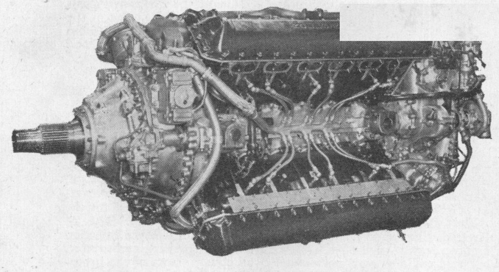
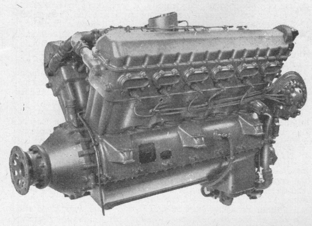
First run in May 1937, the Rolls-Royce Vulture liquid-cooled engine had its 24 cylinders arranged in four banks of six, in the form of an X, and may be considered as two Kestrel-size units with a common crankshaft. It was test flown in a modified Hawker Henley and was used on operations in Avro Manchester bombers, though various troubles, and the desirability of concentrating on the Merlin and Griffon, led to discontinuance of development. (The basic Manchester airframe, with four Merlins in place of two Vultures, became the splendidly successful Lancaster.) The Vulture was also installed in the Hawker Tornado fighter and Vickers-Armstrongs Warwick bomber.
Although the Vulture used cylinders of the same bore and stroke of the Kestrel, the redesigned cylinder blocks had increased cylinder spacing to accommodate a longer crankshaft, necessary for extra main bearings and wider crankpins.
Few details of the engine were ever released, but when it was first described in Flight, in June 1942, it was noted that the capacity was 2,592 cu in. Maximum power ratings were 1,845 h.p. at 3,000 r.p.m. at 5,000 ft in low gear, and 1,710 h.p. at 3,000 r.p.m. at 15,000 ft in high gear. Detail construction followed previous practice in that light-alloy cylinder blocks, head and coolant jacket were employed, with “wet” cylinder liners of steel. The crankshaft was carried in seven bearings. Each cylinder had four valves, operated by overhead camshaft, and two sparking plugs; there were two independent screened magnetos. Variabledatum automatic boost control, with two-position mixture control, was used in conjunction with an S.U. twin-choke, down draught carburettor, and there were two vertical air intakes, coupled by a single entry. The two-speed supercharger delivered mixture to two trunk pipes, each feeding two blocks of cylinders.
The engine was originally designed to produce around 1,750 horsepower (1,300 kW), but continuing problems with the Vulture design meant that the engines were derated to around 1,450-1,550 hp in service by limiting the maximum rpm.
The Vulture had been intended to power the Hawker Tornado interceptor, but with the cancellation of Vulture development, Hawker abandoned the Tornado and concentrated on the Hawker Typhoon, which was powered by the Napier Sabre. Likewise, the same cancellation caused the abandonment of the Vulture-engined version of the Vickers Warwick bomber.
The only aircraft type designed for the Vulture to actually go into production was the twin-engined Avro Manchester. When the engine reliability problems became clear, the Avro team persuaded the Air Ministry that switching to a four-Merlin version of the Manchester, which had been in development as a contingency plan, was preferable to retooling Avro’s factories to make the Handley Page Halifax. The resulting aircraft was initially called the Manchester Mark III and then renamed Avro Lancaster, going on to great success as the RAF’s leading heavy bomber.
The engine suffered from an abbreviated development period and the reliability of the Vulture was very poor. Apart from delivering significantly less than the designed power, the Vulture suffered from frequent failures of the big end connecting rod bearings, which was found to be caused by a breakdown in lubrication, and also from heat dissipation problems. Rolls-Royce were initially confident that they could solve the problems, but the company’s much smaller Merlin was already nearing the same power level as the Vulture’s original specification, and so production of the Vulture was discontinued in 1943 after only 538 had been built.
This special racing engine, first developed for the Supermarine S.6s participating in the Schneider Trophy Contest of 1929, was a development of the Buzzard, and having most moving parts in common with that engine, it differed considerably in appearance. External modifications, made in order to allow better streamlining, affected the valve covers, cylinder blocks, bottom cover and bearer feet. Auxiliaries were redisposed to reduce the depth, and the length of the reduction-gear housing was increased in order to fine down the cowling lines. The gear itself was of 6 : 1 ratio. A major factor in achieving the output of 1,900 h.p. at 2,900 r.p.m. was an entirely new supercharger.
The 1931 model gave 2,300 h.p. at 3,200 r.p.m. for a weight of only 1,630 lb. This meant that the power had increased 21 per cent for a weight increase of only 6.5 per cent, an advance obtained largely by increasing the engine speed, the supercharger gear ratio and the size of the air intake.
Rolls-Royce decided that a one-hour run at full power should be the first mark to be passed before the 1931 “R” engines could be delivered as airworthy. By the end of April the early specimens were usually lasting about 20 min before some kind of failure. By the middle of July they would still only do about half an hour non-stop; but on August 3rd a run of 58 min was accomplished at 2,360 h.p., and on August 12th one hour non-stop was completed at 2,350 h.p.
As part of the re-design of the 1931 engine, an entirely new type of connecting rod was developed, and very considerable modifications were effected in the crankshaft and crankcase, to withstand the terrific loads. “Some idea of the magnitude of the crank-chamber stresses,” Flight remarked, “may be gained from the fact that the load on the centre main bearing due to centrifugal and inertia forces was no less than nine tons. Alternative bearing metals were tried, but white metal was finally made to stand up. An obscure trouble experienced at one time was sidelashing of the big-end bearings against the webs, which caused failure of the white metal on either side of the big ends.”
Considerable trouble occurred with valve springs, more than was expected, considering that the speed was raised by only 300 r.p.m.; in fact, at one time two or three would be found broken after a ten-minute run. Extensive tests were run on a valve-spring rig consisting of one cylinder block. and all aspects of design and material were thoroughly reviewed. The springs finally arrived at were somewhat reactionary, but no further failures at all were experienced on the engines after fitting them.
“The oil consumption,” Flight reported, “rose to terrific figures at the 1931 speeds and powers, partly owing to great quantities lost through the breathers. On one 25-min run the oil consumption was at the rate of 112 gallons an hour. By weeks of work on combinations of scraper rings and crankcase breathers, by modification of the scavenging system, and by the final adoption of a deeper sump which filled all the available space in the machine, the consumption was reduced to about 14 gallons an hour for the final race engines. It also effected a considerable reduction in the oil temperature rise through the engine; oil entered the engine at about 80 deg C and came out at about 140 deg C. The oil used was pure castor.”
The fuel to be used was the subject of many tests, for a compromise had to be effected between power and specific consumption. Invaluable assistance was rendered by the Ethyl Export Corporation. The plugs used in both 1929 and 1931 were Lodge Type X170, which gave very little trouble indeed. During the course of development it was found that an actual engine-run was a more severe test of insulation and general performance than anything the plug-makers could impose themselves.
It was decided to give all plugs an endurance test in an engine before sending them to Calshot. After this run they were returned to the Lodge firm, who examined the inners, repolished them and fitted new outer bodies, before despatching them to Calshot. A few doubtful cases, which might have caused trouble in flight, were found in this way. Actually, no plug troubles of any description were experienced in the air, and the same plugs could be used for warming-up and taxying as for full-throttle flying.
Both B.T.H. and Watford magnetos were used on the race engines. Some trouble was experienced with these on the test-bed, due to the vibration to which they were subjected; consequently every nut on them had to be split-pinned, and certain parts had to be stiffened up.
Before despatch the engines were tested in a hangar with an airscrew fitted. The tick-over speed was set at 475 r.p.m., and the engines were remarkable (as racing units) for their tick-over and flexibility. Once in the aircraft they were started by compressed air or with a Bristol gas starter.
Hiduminium alloys (R.R.50 series) were extensively used and, the life of the engines being short, aluminium-alloy forgings replaced bronze and steel in many parts. From the experience gained from many smashed-up engines, a “life of parts” list was drawn up, and pieces were scrapped after their allotted span, whether broken or not. This procedure was found to be cheaper and quicker than rebuilding smashed engines. There was hardly a single component part in the engine which did not receive design attention and which was not improved in someway-from large units like the crankcase and cylinders down to individual nuts and bolts all over the engine.
For short periods powers appreciably greater than 2,350 b.h.p. were obtained from the “R,” and on September 9th, 1931, a power of 2,530 h.p. was taken from a “sprint” engine, enabling an S.6B to establish a world record of 407.5 m.p.h.
The total production of “R” engines was 20.
Engines of the “R” type were used not only in the S.6, S.6A and S.6B seaplanes, but for land-speed records in Bluebird, Speed of the Wind and Thunderbolt and for water-speed records in Miss England If and III and Bluebird II and III.
The D-12 was one of the most powerful engines of its era, and continued to swap records with other contemporary high-power engines. No British company could offer anything like it, and when Fairey imported 50 of the type (renaming them as the Fairey Felix) the Air Ministry had enough and ordered Napier & Son and Rolls-Royce to start work on cast-block engines of their own.
Arthur Rowledge, one of Napier’s chief engineers and the designer of the Napier Lion engine, became fed up with management and left for Rolls. In this one move any Napier design effort ended while Rolls’ got a boost. Applying every known advance since the D-12 was introduced, Rowledge designed the new engine to use supercharging at all altitudes, allowing it to outperform naturally aspirated engines by as much as they were willing to increase the boost pressure.
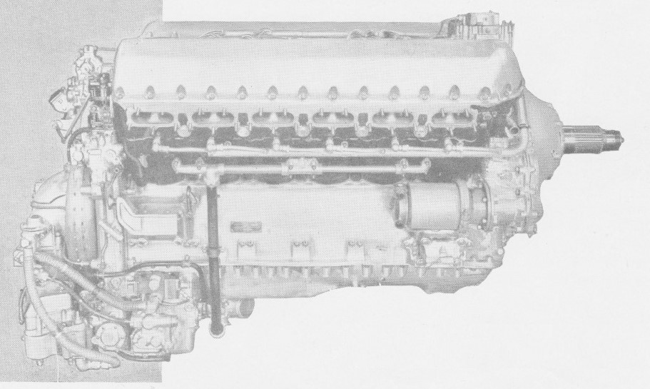
The year 1925 saw the beginnings of a new engine which differed radically from its forebears in having each of the two banks of six cylinders formed from a single aluminium-alloy block. Of 21.24 litres capacity, it was of compact design and first appeared, under the designation F.10, as a direct drive unit. During June 1927 Flight was able to announce that the F.10 had completed its official 100 hr type test at the first attempt, and had been granted a Certificate of Airworthiness. The maximum b.h.p. was 490 at 2,350 r.p.m. and the fuel consumption, at normal power and speed, 30 gal/hr. Dry weight was 760 lb.
The blocks were set at an angle of 60 deg, the cylinder heads, with the necessary inlet and exhaust passages, being cast integrally with the walls forming the water-jackets. Renewable valve-seating rings were screwed into the heads and the valve-guide bushes were of cast iron. The flanged joint between the upper end of the carbon steel cylinder liner and the head was made gas-tight by a soft aluminium ring, and near the lower end of the liner a sliding watertight joint was formed by means of a rubber ring fitted into a groove in the liner. Just below this joint a flange formed on the liner abutted on the crankcase and the whole assembly was held in position by long bolts. Where these bolts passed through the water space between the liners they were enclosed in aluminium tubes, swaged at the ends to make a watertight joint with the jacket casting. The two inlet and two exhaust valves per cylinder were operated by an overhead camshaft, through a separate rocker for each valve.
The three oil pumps were of the gear type and were driven by spur gearing from the vertical shaft which drove the water pump. Lubrication was on the dry-sump principle.
The engine was fitted with hand-starting gear, comprising a worm wheel incorporating a multi-plate clutch mounted on the sleeve carrying the main bevel wheel for the auxiliary drive; the clutch was set to slip when a predetermined torque was exceeded. In the event of backfire also the clutch would slip, thus saving the gears from damage.
In Kestrel engines of the types A and B, two Rolls-Royce Duplex carburettors were mounted between the cylinder blocks. The two throttles of each carburettor were connected by a pair of toothed quadrants, and one quadrant of each pair was mounted on the end of a longitudinal shaft so that all four throttles were opened and closed simultaneously and to the same extent. The carburettors were fitted with a device by which the flow of petrol from the float chamber to the jet was automatically regulated in accordance with altitude.
The supercharger consisted of a high-speed centrifugal fan mounted co-axially with the crankshaft at the rear of the engine and drawing air through the carburettors. The aluminium-alloy impeller, with radial blades, was driven through a speed-multiplying gear comprising a system of three planets. These were frictibnally driven from a pinion on the crankshaft by means of slippers, held in engagement with the insides of the gear rims by light springs. As the speed of rotation of the crankshaft-and therefore of the slippers-increased, the radial pressure of these springs was augmented by centrifugal force, and consequently the torque which the planets could transmit increased as the square of the speed. As the torque required to drive the impeller increased at a like rate, the gear was capable of driving the impeller with a predetermined margin of torque above that causing slip, which was constant throughout the working range of speed.
The object of this special friction drive was to protect the gearing against damage on sudden acceleration or deceleration of the crankshaft due to the inertia of the impeller. The impeller inertia, however, in combination with the friction drive, served to damp out torsional oscillations of the shaft which drove the camshaft and auxiliaries, including the supercharger itself.
For all the varieties of Kestrel so far mentioned the normal crankshaft speed was 2,250 r.p.m. and at this speed the unsupercharged low-compression engine developed 490 h.p. at sea level. The unblown high-compression types gave 480 h.p. up to 3,000 ft, the medium-supercharged models 525 h.p. at sea level and 500 h.p. at 3,000 ft, and the fully supercharged versions 480 h.p. at 11,400 ft.
The next series of Kestrels bore the series numbers IV, V, VI, VII, VIII, IX, X, XI and XII. Of these the IV, V and VI were fully supercharged, with 0.632, 0.5S3 or 0.477 reduction gear; the VII, VIII and IX were medium supercharged, with the same sequence of gear ratios; and the X, XI and XII were unsupercharged, with a compression ratio of 7A. The fully supercharged engines were rated at 600 h.p. at 11,000ft, and the medium supercharged and unsupercharged versions at 630 h.p. at 3,000ft and 575 h.p. at sea level respectively.
The ultimate in Kestrel development were the Series XIV, XV and XVI, fully supercharged, but more highly rated than the IV, V and VI. The supercharger ran at 9.4 times the crankshaft speed, whereas on the IV, V and VI it ran at 8.8 times that speed. The rating was 690 h.p. at 2,600 r.p.m. (an increase of 100 r.p.m. over the earlier engines) at 11,000 ft, and at 3,000 r.p.m. the output was 745 h.p. at 14,500 Oft. The weight was 975 lb.
Kestrel XVI
The Kestrel XXX was a later development for training aircraft, and had a rated power of 535 h.p. at 12,500 ft.
One key advance in the Kestrel was the use of a pressurised cooling system. Water boils at 100 °C at standard atmospheric pressure, but this temperature decreases with altitude. Since the amount of heat carried out of the engine is a function of coolant temperature and volume, if the coolant has to be kept below boiling point an increasing amount of fluid has to be used, along with an increasingly large radiator to cool it. The solution was to pressurise the entire cooling system, thereby not only preventing the decrease in cooling performance with altitude, but in fact increasing the boiling point even on the ground. The Kestrel was built to maintain enough pressure to maintain the boiling point at about 150 °C.
In May of the following year Flight again reported on the development of the “F” series, introducing the F.12, and desscribing it as “in a general way the geared version of the F.1W’ Later, fuller designations and characteristics of the “F” series were made known; thus the FXIA, FXIB, FXIIA and RXIM differed with regard to gear ratio and compression ratio; the FXI engines had a gear ratio of 0.632:1, and the FXII a ratio of 0.552:1. The letters A and B indicated compression ratios of 6:1 and 7:1 respectively. SubsequentIv, the FXIVA and FXIVB were added to the series; the FXIV had a gear ratio of 0.475:1.
During 1930 the “F” type engine was named the Kestrel, and yet another system of designation was introduced. The name was followed by the series number I, II or III, indicating 0.632, 0.552 and 0.475 reduction gear ratios respectively; then followed the letters A, B, MS, or S, indicating 6:1 compression, 7:1 compression, medium supercharger, or full supercharger.
The Kestrel was first produced in 1927 at 450 hp (340 kW), which soon improved in the IB version to 525 hp (390 kW). This variant saw widespread use in the Hawker Hart family that was the mainstay of British air power during the early 1930s. However it was not long before line improvements increased power dramatically; the V model provided 695 hp (520 kW) at 3,000 rpm with no basic change to the design, while the XVI used in the Miles Master delivered 670 hp (500 kW). Messerschmitt also tested its first Messerschmitt Bf 109 V1 prototype, bearing German civilian registration D-IABI, with a Kestrel engine in 1935 as the German designed intended engines were not yet ready. Junkers also used a Kestrel for the first prototype of the Ju 87 “Stuka” dive bomber. The Reich Air Ministry (RLM) acquired four Kestrel VI engines by trading Rolls-Royce a Heinkel He 70 Blitz as an engine test-bed.
Increased availability of higher octane aviation fuels in the late 1930s allowed the engine to be boosted to higher power levels without suffering from detonation, and the Kestrel eventually attained a power output of 720 hp (537 kW) in the XXX variant of 1940.
The Kestrel was produced in 40 distinct variants which can be divided into three main groups, normally aspirated, medium supercharged and fully supercharged. One variant, the Kestrel VIII was configured as a ‘pusher engine’ for the Short Singapore flying boat. Apart from supercharging, the variant differences centred around varying compression ratios and propeller reduction gearing.
The total production of Kestrel engines was 4,750. Unit cost in 1934 was £2,051. Further developments of the Kestrel were the Goshawk and the Peregrine (and therefore the Vulture).
Aircraft applications: Airco DH.9 Avro Antelope Blackburn Nautilus Blackburn Sydney Fairey Fleetwing Fairey Hendon Fairey S.9/30 Fairey Fox I, II, III and IV, IIIF Fairey Firefly II and III Fokker C.V Fokker C.X Fokker D.XVII Gloster Gnatsnapper Gloster TC.33 Gloster TSR.38 Gloster C.16/28 Handley Page Hamilton Handley Page Heyford Handley Page H.P.30 Hawker Audax Hawker Demon Hawker Fury Hawker Hardy Hawker Hart Hawker Hind Hawker Hornet Hawker Nimrod Hawker Osprey Hawker High-Speed Fury Hawker Hartebeeste Heinkel He 70 G-1 Heinkel He 112 Henschel Hs 122 Junkers Ju 86 Junkers Ju 87 Messerschmitt Bf 109 Miles Master Miles Kestrel Parnall Pipit Praga E-45 Renard R.31 Saro A.10 Short Gurnard Short Singapore Supermarine Scapa Supermarine Southampton Vickers 141 Vickers B.19/27 Vickers F.21/26 Vickers Type 150 Vickers Type 163 Westland Wizard
Other applications Speed of the Wind
Specifications: Kestrel V Type: Supercharged liquid-cooled 60-degree V12 engine Bore: 5 in (127 mm) Stroke: 5.5 in (140 mm) Displacement: 1,295.88 in³ (21.24 L) Length: 74.61 in (1,895 mm) Width: 24.41 in (620 mm) Height: 35.63 in (905 mm) Dry weight: 957 lb (434 kg) Valvetrain: Two inlet and two exhaust poppet valves per cylinder Supercharger: Gear-driven centrifugal type supercharger Fuel system: Rolls-Royce carburettor Fuel type: 87 octane petrol Cooling system: Liquid-cooled, pressurised to 300°F (150°C) Reduction gear: Spur, 0.553:1 Power output: 685 hp (511 kW) at 2,240 rpm for takeoff 631 hp (471 kW) at 2,900 rpm at 14,400 ft (4,400 m) Specific power: 0.53 hp/in³ (24.05 kW/L) Compression ratio: 6.0:1 Oil consumption: 0.18-0.35 oz/(hp/hr) (7-13 g/(kW/hr)) Power-to-weight ratio: 0.72 hp/lb (1.18 kW/kg)
According to Arthur Rubbra’s memoirs, a de-rated version of the “R” engine, known by the name Griffon at that time, was tested in 1933. This engine, R11, which was never flown, was used for “Moderately Supercharged Buzzard development” (which was not proceeded with until much later), and bore no direct relationship to the volume-produced Griffon of the 1940s.
The Griffon 37.V.12 was originally developed to meet Fleet Air Arm requirements specifically, to give high powers at low altitudes and thus to be suitable for installation in torpedo-bombers. The decision to go ahead with it was taken in December 1939, and it was recognized that the same basic engine should be suitable for installation in existing fighters, then powered with the Merlin.
On 8 November 1939 N E Rowe of the Air Ministry suggested fitting the Griffon in a Spitfire. Three weeks later permission was given to Supermarine to explore the possibilities of adapting the Griffon to the Spitfire; in response Supermarine issued ‘Specification 466’ on 4 December. This decision led to a change in the disposition of the engine accessories to reduce the frontal area of the engine as much as possible. As a result the frontal area of the bare Griffon engine was 7.9 square feet (0.73 m2) compared with 7.5 square feet (0.70 m2) of the Merlin. This redesigned engine first ran on 26 June 1940 and went into production as the Griffon II.
In early-1940, on the orders of Lord Beaverbrook, Minister of Aircraft Production, work on the new engine had been halted temporarily to concentrate on the smaller 27 L (1,650 cu in) Merlin and the 24 cylinder Vulture which had already surpassed the output achieved with the early Griffon.
Relative frontal areas were 7.5 sq ft and 7.9 sq ft. “It would seem well-nigh impossible,” Flight remarked, when describing the Griffon for the first time, “that with such similarity of overall dimensions in two engines of the same basic type the swept volume of one should be 35.9 per cent larger than that of the other. Piston area of the Griffon is 23 per cent greater than that of the Merlin, this having been achieved by increasing the cylinder bore to 6in.”
Though following Merlin lines, the Griffon differed very extensively in detail design. A prominent innovation was the taking of the camshaft and magneto drives from the front; this was decided upon in order to reduce torsional vibration in the camshaft drive. By interpolating a semi-floating coupling between the crankshaft and the driving wheel of the reduction gearing, and, in addition, by taking the cam drives from the airscrew-driving gear, angular variations in crankshaft speed were greatly reduced in their transmission to the camshafts.
A feature of the crank assembly is that the main bearings and big ends are all lubricated from the hollow interior of the shaft.
In 1938 the Fleet Air Arm approached Rolls-Royce and asked whether a larger version of the Merlin could be designed. The requirements were that the new engine have good power at low altitude and that it be reliable and easy to service. Work began on the design of the engine soon afterwards. The design process was relatively smooth compared with that of the Merlin, and the first of three prototype Griffon Is first ran in the Experimental Department on 30 November 1939.
Compared with earlier Rolls-Royce designs, the Griffon engine featured several improvements which meant it was physically only slightly larger than the Merlin, in spite of its 36% larger capacity of 37 litres (2,260 cu in). One significant difference was the incorporation of the camshaft and magneto drives into the propeller reduction gears at the front of the engine, rather than using a separate system of gears driven from the back end of the crankshaft; this allowed the overall length of the engine to be reduced as well as making the drive train more reliable and efficient. The Griffon was the first Rolls-Royce production aero engine to use a hollow crankshaft as the means of lubricating the main and big end bearings, providing a more even distribution of oil to each bearing. In another change from convention, one high efficiency B.T.H-manufactured dual magneto was mounted on top of the propeller reduction casing; earlier Rolls-Royce designs using twin magnetos mounted at the rear of the engine.
First run in November 1939, early Griffons-the II, III and IV-had two-speed, single stage blowers, and gave a maximum power of 1,735 h.p. at 16,000 ft and 1,495 h.p. at 14,500 ft. For take-off 1,720 h.p. was available. These engines differed in reduction gear ratio, the II and III being geared 0.451:1, and the 4, 0.510:1. Until superseded by the Griffon XII the series II engine was installed in the Firefly I and II; the Griffon III and IV were mounted in the clipped-wing Spitfire XII specially developed to tackle the Fw 190 at low and medium levels. By increasing boost pressure to 15 lb/sq in the take-off power of the Griffon VI was raised to 1,815 h.p., an increment of importance in that this engine powered the Seafire XV and XVII carrier-borne fighters. The Griffon XII resembled the VI except in supercharger and reduction gear ratios; it delivered 1,645 h.p. at 11,500 ft.
The system of designating the two-stage supercharged Merlins with series numbers beginning with 6 was also adopted for the Griffon range. For a weight increase of 290 lb, accounted for by the new blower system, the Griffon 61 delivered 2,035 h.p. at 7,000 ft and 1,820 h.p. at 21,000 ft; its most famous application was in the Spitfire 21. Identical in all but reduction gear, the Griffon 65 powered the Spitfire XIV, and the Griffon 66 was again similar but had a cabin supercharger for P.R. work in the Spitfire XIX. Griffons 64 and 67 were derived, respectively, from the 61 and 64, and gave no less than 2,375 h.p. at 1,250ft, and 2,145 h.p. at 15,500 ft; the 64 powered the Spitfire 21 and Seafire 46, and the 67 appeared in the Spitfire XIV.
The Griffon 61 series introduced a two stage supercharger and other design changes: the pressure oil pumps were now housed internally within the sump and an effort was made to remove as many external pipes as possible. In addition, the drive for the supercharger was taken from the crankshaft at the back of the engine, via a short torsion shaft, rather than from the front of the engine, using a long drive shaft as used by earlier Griffon variants.
Though early examples of the Vickers-Supermarine Spiteful had the Griffon 61, the production model had the Griffon 69, the maximum power of which exceeded that of the earlier two stage Griffons by some 300 h.p., with no increase in weight. Official maximum powers were 2,375 h.p. at 1,250ft in M.S. gear, and 2,130 h.p. at 15,500 ft in F.S. gear. Boost pressure was plus 25 lb/sq in, made possible by 150 grade fuel.
Griffons 72 and 74 were further developments of the 65 for the Fleet Air Arm; they delivered 2,245 h.p. at 9,250ft. The 74 was distinguished from the 72 in having a Rolls-Royce injection pump instead of the Rolls-Royce Bendix/Stromberg carburettor. These engines were, respectively, the power plants of the prototype Firefly IV and production Fireflies of the same mark.
Basic component overview – Griffon 65
Cylinders Twelve cylinders consisting of high-carbon steel, floating wet liners set in two, two-piece cylinder blocks of cast aluminium alloy having separate heads and skirts. Cylinder liners chromium plated in the bores for 2 1⁄2 inches from the head. Cylinder blocks mounted with an included 60-degree angle onto inclined upper faces of a two-piece crankcase. Cylinder heads fitted with cast-iron inlet valve guides, phosphor bronze exhaust valve guides, and renewable “Silchrome” steel-alloy valve seats. Two diametrically opposed spark plugs protrude into each combustion chamber. Pistons Machined from “R.R.59” alloy forgings. Fully floating gudgeon pins of hardened nickel-chrome steel. Two compression and one drilled oil-control ring above the gudgeon pin, and another drilled oil-control ring below. Connecting rods H-section machined nickel-steel forgings, each pair consisting of a plain and a forked rod. The forked rod carries a nickel-steel bearing block which accommodates steel-backed lead-bronze-alloy bearing shells. The “small-end” of each rod houses a floating phosphor bronze bush. Crankshaft One-piece, machined from a nitrogen-hardened nickel-chrome molybdenum steel forging. Statically and dynamically balanced. Seven main bearings and six throws. Internal oilway, with feed from both ends, used to distribute lubricants to main and big end bearings. “Floating” front end bearing consisting of an internally toothed annulus bolted to crankshaft, meshing with and incorporating a semi-floating ring, internally splined to a short coupling shaft. Coupling shaft splined at front end to driving wheel of propeller reduction gear. Clockwise rotation when viewed from rear. Crankcase Two aluminium-alloy castings joined together on the horizontal centreline. The upper portion bears the wheelcase, cylinder blocks and part of the housing for the airscrew reduction gear; and carries the crankshaft main bearings (split mild-steel shells lined with lead–bronze alloy). The lower half forms an oil sump and carries the main pressure oil pump, supercharger change-speed operating pump and two scavenge pumps. It also houses the main coolant pump which is driven through the same gear-train as the oil pumps. Wheelcase Aluminium-alloy casting fitted to rear of crankcase. Carries the supercharger; and houses drives to the supercharger, auxiliary gearbox coupling, engine speed indicator, airscrew constant-speed unit, intercooler pump and fuel pump, as well as the oil and coolant pumps in the lower half crankcase. Valve gear Two inlet and two exhaust poppet valves of “K.E.965” austenitic nickel-chrome steel per cylinder. Exhaust valves have sodium-cooled stems. “Brightray” (nickel-chromium) protective coating to the whole of the combustion face and seat of the exhaust valves, and to the seat only of the inlet valves. Each valve is held closed by a pair of concentric coil springs. A single, seven-bearing camshaft, located centrally on the top of each cylinder head operates 24 individual steel rockers; 12 pivoting from a rocker shaft on the inner, intake side of the block to actuate the exhaust valves, the others pivoting from a shaft on the exhaust side of the block to actuate the inlet valves.
An innovation of more than usual interest was the adoption, on the Griffon 85, of a drive for contra-rotating airscrews; this engine appeared in the Spitfire XIV, 21 and Seafire 45. The Griffon 87 was a further development, rated at 2,145 h.p. maximum at 15,500 ft, and the 88 differed only in having an injection pump. “Contraprop” Griffons, of the 85, 87 and 88 series, were mounted in the Spitfire XIV and 21, and Seafire 45 and 47.
For the Barracuda V Rolls-Royce developed the Griffon 37, with a modified two-speed, single-stage blower, maintaining 18 lb/sq in boost in either gear. Though the Barracuda was provided with 2,055 h.p. at 2,250 ft, only Merlin powered machines of this type went into squadron service.
The most impressive of all Griffon developments was the three-stage supercharger incorporated in the 101 series, together with Rolls-Royce fuel injection. The new blower made possible an output of over 2,000 h.p. up to 20,000 ft with no increase in dimensions. Weight rose by 40 lb.
Notable among post-war developments is the Griffon 67, for use in long-range Service aircraft and having provision for contra-rotating airscrews. On this engine water/methanol injection is automatically brought into play when the boost pressure for the standard fuel approaches maximum value. The controlling unit works in conjunction with the boost control and progressively increases the flow of water methanol with boost pressures from 18.5 to 25 lb/sq in. Contraprop Griffons power the Avro Shackleton maritime-reconnaissance aircraft. Other variants of the Griffon are serving in the numerous marks of Fairey Firefly.
Unlike the Merlin, the Griffon was designed from the outset to use a single-stage supercharger driven by a two-speed, hydraulically operated gearbox; the production versions, the Griffon II, III, IV, and VI series, were designed to give their maximum power at low altitudes and were mainly used by the Fleet Air Arm. The Griffon 60, 70, and 80 series featured two-stage supercharging and achieved their maximum power at low to medium altitudes. The Griffon 101, 121, and 130 series engines, collectively designated Griffon 3 SML, used a two-stage, three-speed supercharger, adding a set of “Low Supercharger (L.S)” gears to the already existing Medium and Full Supercharger (M.S and F.S) gears. Another modification was to increase the diameters of both impellers, thus increasing the rated altitudes at which maximum power could be generated in each gear.[18] While the 101 continued to drive a five-blade propeller, the 121 and 130 series were designed to drive contra-rotating propellers. In 1946 a Griffon 101 was fitted to the Supermarine Spiteful XVI, RB518 (a re-engined production Mk.XIV); this aircraft achieved a maximum speed of 494 mph (795 km/h) with full military equipment.
The Griffon was the last in the line of V-12 aero engines to be produced by Rolls-Royce with production of the aero version ceasing in December 1955 after 8,108 were built, the Griffon 130 being the last in the series. Griffon engines remained in Royal Air Force service with the Battle of Britain Memorial Flight and power the last remaining airworthy Avro Shackleton.
A marine version, the Sea Griffon, continued to be produced for the RAF’s High Speed Launches.
Several North American Mustangs raced in the Unlimited Class races at the Reno Air Races have been fitted with Griffons. These include the RB51 Red Baron (NL7715C), “Precious Metal” (N6WJ) and a Mustang/Learjet hybrid “Miss Ashley II” (N57LR).[33] In all cases, Griffons with contra-rotating propellers, taken from Avro Shackleton patrol bombers were used in these aircraft. The RB51 Red Baron is noteworthy for holding the FAI piston-engine 3-kilometer world speed record from 1979 to 1989.
In 1965, SFR Yugoslavia used Griffon engines as the main power unit for their first domestically produced self-propelled artillery system, the S65, but the system was withdrawn from service in the early 1980s, because of poor fuel economy.
The 1980 Miss Budweiser Unlimited Hydroplane dominated the race circuit with a Rolls-Royce Griffon engine. It was the last of the competitive piston-engined boats, before turboshaft powerplants took over.
In modern day tractor pulling, Griffon engines are also in use, a single or double, rated each at 3,500 hp (2,600 kW).
Type: 12-cylinder supercharged liquid-cooled 60° Vee aircraft piston engine Bore: 6 in (152.5 mm) Stroke: 6.6 in (167.6 mm) Displacement: 2,240 cu.in (36.7 L) Length: 81 in (2,057 mm) Width: 30.3 in (770 mm) Height: 46 in (1,168 mm) Dry weight: 1,980 lb (900 kg) Valvetrain: Two intake and two exhaust valves per cylinder with sodium-cooled exhaust valve stems, actuated via an overhead camshaft. Supercharger: Two-speed, two-stage centrifugal type supercharger, boost pressure automatically linked to the throttle, water-air intercooler installed between the second stage and the engine. Fuel system: Triple-choke Bendix-Stromberg updraught, pressure-injection carburettor with automatic mixture control Fuel type: 100 Octane (150 Octane January to May 1945) Oil system: Dry sump with one pressure pump and two scavenge pumps Cooling system: 70% water and 30% ethylene glycol coolant mixture, pressurised. Liquid-cooled Intercooler radiator with its own separate system, again using 70/30% water/glycol mix. Reduction gear: 0.51:1, left-hand tractor Power output: 2,035 hp (1,520 kW) at 7,000 ft (2,135 m MS gear), +18 psi boost pressure at 2,750 rpm 2,220 hp (1,655 kW) at 11,000 ft (2,135 m MS gear), +21 psi at 2,750 r.p.m using 150 Octane fuel 1,820 hp (1,360 kW) at 21,000 ft (6,400 m) at 2,750 rpm Specific power: 0.91 hp/cu.in (41.4 kW/L) Compression ratio: 6:1 Power-to-weight ratio: 1.03 hp/lb (1.69 kW/kg)
Variants:
Griffon IIB 1,730 hp (1,290 kW) at 750 ft (230 m) 1,490 hp (1,110 kW) at 14,000 ft (4,270 m) Single-stage two-speed supercharger Impeller diameter 10 in (25.4 cm) Gear ratios 7.85:1, 10.68:1. Used on Firefly Mk.I and Spitfire XII.
Griffon VI Increased maximum boost pressure 1,850 hp (1,380 kW) at 2,000 ft (610 m) Impeller diameter 9.75 in (24.7 cm) Used on Seafire Mk.XV and Mk. XVII, Spitfire XII.
Griffon 57 and 57A 1,960 hp (1,460 kW) 2,345 hp (1,749 kW) with water-methanol injection on take-off Used on Avro Shackleton.
Griffon 58
Griffon 61 Introduced a two-speed two-stage supercharger with aftercooler similar to that on Merlin 61 2,035 hp (1,520 kW) at 7,000 ft (2,100 m) 1,820 hp (1,360 kW) at 21,000 ft (6,400 m) Used on Spitfire F.Mk.XIV, Mk.21.
Griffon 65 Similar to Griffon 61 with different propeller reduction gear Impeller diameters 1st stage: 13.4 in (34 cm), 2nd stage: 11.3 in (29 cm) Used on Spitfire F.Mk.XIV.
Griffon 72 Increased maximum boost pressure to take advantage of 150-grade fuel 2,245 hp (1,675 kW) at 9,250 ft (2,820 m)
Griffon 74 Fuel-injected version of Griffon 72; used on Firefly Mk.IV
Griffon 83 Modified to drive contra-rotating propellers 2,340 hp (1,745 kW) at 750 ft (230 m) 2,100 hp (1,565 kW) at 12,250 ft (3,740 m)
Griffon 85 2,375 hp (1,770 kW) Used on Spiteful Mk.XIV
Griffon 89 2,350 hp (1,755 kW) Used on Spiteful Mk.XV
Griffon 101 2,420 hp (1,805 kW) Two-stage, three-speed supercharger using Low Supercharger (L.S), Moderate Supercharger (M.S), or Full Supercharger (F.S) Reduction gear ratio 4.45 Rolls-Royce fuel injection system Used on Spiteful Mk.XVI
Griffon 130 2,420 hp (1,805 kW) at 5,000 ft (1,524 m) in L.S gear 2,250 hp (1,678 kW) at 14,500 ft (4,419 m) M.S 2,050 hp (1,529 kW) at 21,000 ft (6,400 m) F.S Reduction gear ratio 4.44 Modified to drive contra-rotating propellers Rolls-Royce fuel injection system