First flown in 1934 DH Gipsy Six.
Inter-Wars
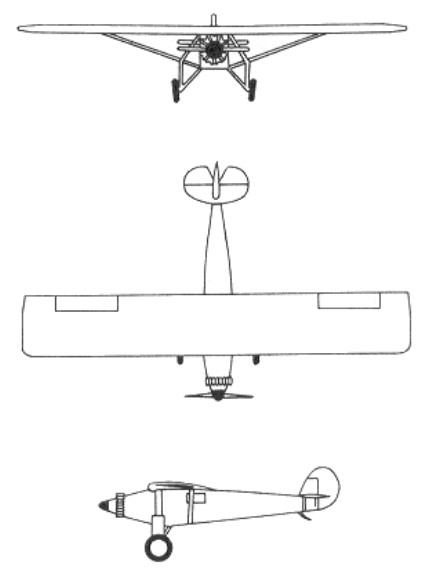
ASJS Viking I
First flown in June 1931
Cirrus-Hermes, 105hp
Later repowered Walter Gemma, 150 hp
Svenska Aero Jaktfalken / J5 / J6
1929 prototype
Armstrong Siddeley Jaguar, 425 hp
1 to Swedish Air force as J5, 1 to Norway
Re-engined Bristol Jupiter VI as J6A
Bristol Jupiter VII as J6B
SAAB
Svenska Aero
AB Svenska Järnvägsverkstäderna (ASJA)
Svenska Aeroplan Aktiebogalet (SAAB)
Svenska Aero, as a subsidiary of Heinkel, was taken over by AB Svenska Järnvägsverkstäderna (ASJA) in 1932.
The Bofors Company at Trollhattan formed in 1937 Svenska Aeroplan Aktiebogalet (SAAB). Following its merger in 1939 with the AB Svenska Jarnvagsverkstadernas Aeroplanavdelning (AJSA). In 1939 amalgamated with Aircraft Division of Svenska Jarnvagsverkstaderna and moved main establishment to Linkoping. From 1950 acquired other important facilities, including underground factory at Linkoping.
Built 82 Tiger Moth, 43 Hawker Hart, 11 NA-16-4M, FW-44, and Northrop 8A-5 under licence.
In 1945, in the hope of a lasting peace, the Company decided to scale down its production of military aircraft and to develop its civilian operations – a change in policy signified by the ap¬pearance of the Saab 90 Scandia airliner and the Saab 92 car.
Name changed to Saab Aktiebolag May 1965; Malmo Flygindustri became a subsidiary in 1967; in 1968 merged with Scania-Vabis group to became Saab-Scania. Current name Saab Group, comprising five main divisions: Saab AB, Saab Dynamics AB for guided weapons and electronics, Saab Training Systems AB, Saab Aircraft AB for marketing and supporting commercial aircraft, and Saab Combitech AB. Saab AB parent division established January 1997 to combine activities of previous Saab Military Aircraft, Saab Aircraft and Saab Service Partner, and develops and manufactures military and commercial aircraft within business units known as Gripen, General Military Aircraft, Future Products and Technology, Operations Commercial Aircraft, and Collaborative Programs.
First airplanes were license-built Junkers Ju 86K twin-engined bombers, Northrop-Douglas dive-bombers (Douglas 8A-1, similar to the US Army Air Corps’ A-17) and North American NA-16 trainers. First own-design production aircraft was Saab 17 dive-bomber of 1940, used widely and 60 delivered to Ethiopia from 1947. Saab 18 was twin-engined bomber of 1942, some late examples of which had ejection seats. Saab 21A of 1943 was piston-engined single-seat fighter, and 21-R was jet development of the same aircraft. Saab 29 was the so-called “flying barrel” swept-wing jet fighter, in production until 1956, while Saab 32 Lansen of 1952 was swept-wing fighter/attack/reconnaissance two-seater. Saab 35 Draken “double-delta” fighter appeared in 1955, and a squadron remained active as interceptors until 1999. Saab 105 of 1963, a twin-jet light side-by-side two-seater armed multipurpose aircraft, still in use as a trainer in 1999; Swedish Air Force aircraft have just undergone an upgrade with new engines and thus redesignated Sk 60W. Saab 37 Viggen multirole combat aircraft, first flown February 1967, has foreplane and delta wings, and with its STOL capability remains a very potent weapon system. Produced for service between 1971 and 1990, it has been continuously upgraded; redelivered in latest upgraded form 1998 for continued service in JA 37 interceptor and AJS 37 attack/interceptor/maritime-reconnaissance variants. Latest combat aircraft is Saab AB Gripen JAS 39 Gripen, first flown December 1988 and taken into Swedish Air Force service from 1996. Grippen is the world’s first combat aircraft of the new-generation type and the first to combine the roles of interceptor, attack, and reconnaissance in a single aircraft (all as primary roles) by the adoption of push-button control to select the required function in the computer programs of the totally integrated avionics suite.
Civil types have included Saab 90 Scandia twin-engined 32-passenger transport (first flown November 1946); Saab 91 Safir all-metal 3/4-seater (first flown November 1945); two/three-seat high-wing Safari (first flown in July 1969) and its military Supporter development (first flown 1972). In production until 1999 has been the Saab 340 turboprop regional transport (first flown January 1983, and finally produced in 340B and BPIus variants with accommodation for up to 37 passengers) and the Saab 2000 50/58-seat turboprop regional airliner (first flown March 1992). Saab has also developed an airborne early warning and control variant of the 340B airliner as the S100B Argus (first flight of AEW&C prototype with overfuselage radar July 1994), plus a search-and-rescue variant for the Japanese Maritime Safety Agency as the SAR-200 (delivered 1997).
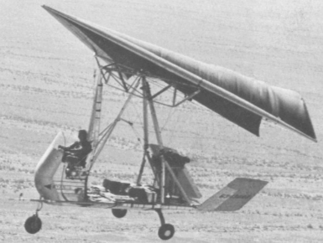
Ryan Flex-Wing / XV-8A Fleep
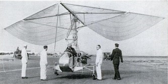
The XV-8A aircraft (designated FLEEP) resulted from Ryan Aeronautical Company design studies of the application of the Rogallo flexible-wing concept to a manned aircraft. This aircraft is an improved version of the origional Ryan flexible-wing manned test vehicle. The aircraft was designed as a single-place, lightweight utility vehicle, capableof carrying a 1000-pound payload and having short-field take-off and landing characteristics.
The US Army Precision Drop Glider was designed and constructed by the Ryan Aeronautical Co. Cecil Craigo was the program manager. This cargo delivery system was designed for a payload of 300 pounds which is contained in a rectangular box attached to the bottom of the wing control platform. Four riser straps are attached to the sides of the control platform and the suspension lines from the wing are attached to the risers.
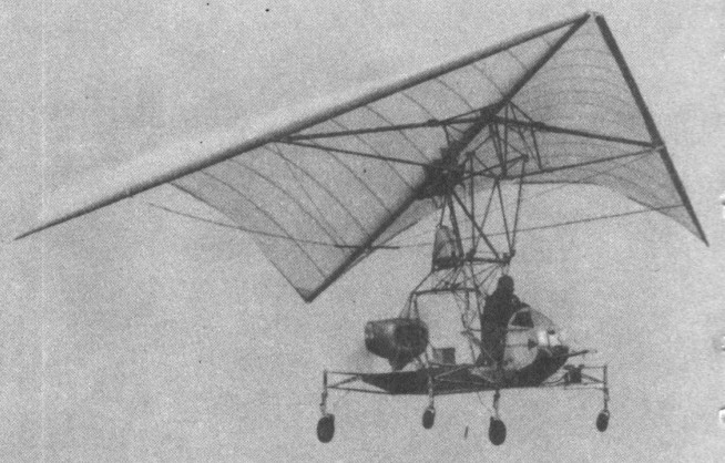
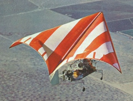
The XV-8A was a delta-shaped, fabric Rogallo wing with inflatable leading edge, attached to a podlike cockpit on a tri-gear platform; V-tail. It folded into a relatively small package for transport. It was nicknamed “Fleep,” short for “Flying Jeep.”
The basic body structure was in the form of a flat deck. A raised platform at the forward end supports the pilot’s seat, nose wheel, control mechanism, instrument panel, and nose fairing. Fittings on the pilot’s seat back and at the sides of the platform attach the wing support struts. Other fittings at the aft end of the platform provide attachment for the engine mount truss and tail surfaces. The useable cargo area, 64 inches wide and 80 inches long, is fitted with twelve standard flush-type cargo tie-down rings. Because of the open-deck design, long slender cargo items may extend both forward and aft of the normal cargo area. Riveted aluminum alloy sheet and extruded sections are utilized in fabricating the platform structure. Jacking pads are provided on the lower surface of the platform at the main landing gear and at the forward end of the cargo area. The forward end of the pilot’s cockpit is a removable fiberglass fairing. The fairing support framework also supports the instrument panel and the transparent plastic windshield. The pilot’s seat, an integral part of the vehicle structure, is equipped with a standard seat belt and shoulder harness. Space has been provided to accommodate a back-pack type parachute.
The wing is composed of three main structural members: a rigid center keel, and rigid right and left leading edges. The two leading edges join the keel at the apex and form a near-triangular wing planform. The keel runs longitudinally aft from the apex along the center line of the wing. The flexible membrane, made of Dacron with a polyester coating, is continuously attached to the leading edges and keel. The leading edges have a 50-degree sweep angle. The total wing area in flat planform is 450 square feet.
The wing had 6-inch-diameter inflated-tube leading edges and keel, which are 22 feet long and a cloth lifting surface. Air for inflating the leading edges and keel is supplied by a high-pressure storage bottle in the rear of the keel. Directional control is achieved by pulling on the suspension line on either wing tip and is actuated by a motor in the control platform. The control system was designed for steering by radio command from a ground or air controller, or by an automatic homing system that seeks a radio beacon located on the ground in the target drop area.
The wing is of the foldable flexible type made up of a rigid keel, two rigid leading edges, a rigid spreader bar, flexible membrane, fittings, and attaching hardware. The forward ends of the leading edges attach to the forward end of the keel to form an apex which sweepsback at a 50 degree angle. The spreader bar which attaches to the keel at about midway, supports the leading edges to produce the proper sweepangle, and transmits the leading edge lift loads to the keel. The wing keel is a tapered sheet aluminum alloy boxtype structure. A fitting at its forward end supports the leading edge members. The keel attaches to the spreader bar by a hinge fitting at the keel 46 percent station. Fittings are provided forward and aft of the main hinge to attach the pitch trim control cables. The leading edges are hollow aluminum alloy spars which have a symmetrical streamlined cross section, and taper from a maximum cross section near the spreader bar attachment toward both ends. An aluminum alloy channel at the maximum cross section serves as a shear web. The attachment at the spreader bar is a swivel fitting with one axis lying along a chord-line and the other axis forward of and parallel to the leading edge. The attachment at the keel is aspherical rod end type fitting. Since the spar is free to align itself to the load, and the wing membrane is attached along the trailing edge, membrane tension is always applied to the plane of maximum spar stiffness. The aft 13-1/2 percent of the leading edge is hinged to permit a 5 degree motion in a chordwise direction to provide additional lateral control. The hinge mechanism incorporates linkage to multiply the mechanical advantage of the actuating cable used to control the position of the hinged leading edge portion in flight.
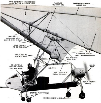
The original wing was nylon sealed with Mylar but this was replaced with Dacron cloth sealed with a resin as the Dacron was more durable in sunlight. The wing membrane fabric is square weave Dacron cloth coated on both sides with olive drab polyester resin. The coated material is flexible and extremely weather resistant. Total weight of the coated fabric is 8 ounces per square yard. The coated fabric has a tensile strength of not less than 200 pounds per inch in the warp direction, and not less than 120 pounds per inch in the fill direction. The membrane is attached along the keel and leading edges with machine screws. Metal reinforcing strips are bonded into the reinforced, bonded, and sewn edges of the membrane. To prevent trailing edge flutter, the aft edge of the membrane is scalloped, and thin wooden battens (3 per lobe) are retained in pockets sewn in the trailing edge membrane. A reinforcing cable, the length of which is adjustable on the ground for roll trim, is sewn into a hem along the aft edge of the membrane.
The wing is folded in a compact package similar to a parachute pack and was located in the control platform before deployment. The cargo box and packaged wing are discharged from an aircraft and wing deployment is initiated by a static line. Deployment loads are attenuated by use of an initial parachute like phase. After the tubes have been inflated the reefing lines are cut, and the wing completes deployment and then makes a transition from vertical flight to gliding flight.
The landing gear is of the tricycle type. The nose and main tires and wheels are the same size and type to minimize spare part requirements. The main landing gear tread is 9.0 feet, and the wheel-base is 10.63 feet. Large, low-pressure type III tires aid operation from soft ground or rough fields. Landing loads at the main wheels are absorbed by cantilever Fiberglas springs extending from both sides of the platform structure. Heat treated steel axles which mount the aluminum alloy wheels are bolted and clamped to the outboard ends of the springs. Single disc type hydraulic brakes incorporated in the main wheels are hydraulically actuated by a master cylinder in the pilot’s cockpit. Pressurized hydraulic fluid is supplied to the brakes through flexible hoses encased in wire braid. An oleo strut type shock absorber is incorporated in the nose landing gear. The nose landing gear assembly attaches to the forward end of the sheet metal platform by a tubular tripod type structure. The nose wheel which can be steered through an angle of 25 degrees either side of center by operating foot pedals in the pilot’s cockpit produces a turning radius of 27.83 feet. The foot pedals are connected to arms extending from the sides of the shock absorber piston tube by a simple cable and pulley system. The nose wheel is aligned in a fore and aft position in flight by a centering cam.
The propulsion system consisted of a six cylinder, aircraft reciprocating engine equipped with a fixed-pitch propeller employed as a pusher, and an exhaust-driven ejector cooling system. A steel tube truss supported the engine near the aft end of the platform structure. Four flexible rubber mounts are used to attach the engine to the truss. The propeller thrust line is inclined 3 degrees up at the rear with respect to the platform surface. The exhaust driven ejector cooling system is self-regulating, and requires no action on the part of the pilot. Sheet aluminum baffles direct the cooling air through cooling fins on the engine cylinders and heads.
A pilot’s seat and the necessary flight controls are provided at the forward end of the platform. An engine, pusher propeller, and a V-tail are mounted at the rear of the platform. Provision is made for manually folding the wing and tail surfaces. A rudder was also added to provide better control in crosswinds and the original engine was replaced with a larger 185 hp engine.
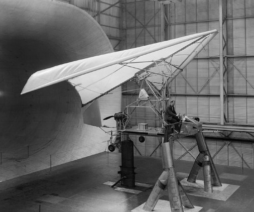
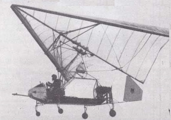
A full scale of XV-8A Fleep prototype, a flexible wing aircraft built by Ryan, was flown in NASA Langley Research Center’s Full Scale Tunnel. The Ryan testbed was not a prototype for a production aircraft. It was for research alone, hence all its cables and linkages were exposed. Adjustmenst could be made without opening panels.
This program was successful in demonstrating the feasibility of aerial delivery of cargo by means of a deployable parawing. It was anticipated that development of this use for a parawing would continue and additional controls can be included to provide flare capability for reduction of landing speeds.
The performance capabilities of the airplane were all within predicted values. The cruise capability was such that a 100-mile mission can be flown at maximum gross weight. Take-off and landing performance proved the STOL capability of the airplane. At maximum gross weight, the take-off distance over a 50-foot obstacle is 1,000 feet. Landing distance to clear a 50-foot obstacle is 400 feet. During the course of the test program, the airplane proved to be a reliable and easy aircraft to maintain and service. Some test operations were conducted from unprepared desert surfaces, establishing the capability for operation from areas other than regular airfields. The operational and flying techniques are basically similar to those of lightweight conventional aircraft. The two-control system lends itself to simplicity and provides adequate control power to permit a fixed wing incidence trim setting for the entire flight including take-off, climb, cruise, descent, and landing.
The handling characteristics of the aircraft were good. Control harmony between the longitudinal and lateral control systems was excellent, enabling the aircraft to be flown with one hand. Stability in all cases was positive with only light forces required. The flight characteristics of this airplane were similar in most respects to those found in a conventional airplane with a comparable light wing loading.
The aircraft was safe and pleasant to fly for an Army pilot of average skill. In flight the craft got light at 30 mph for takeoff and the platform remained level during climb and turns. Occasionally the platform rocked gently back and forth or from side to side in gusty air, yet the cloth remained completely stable. Data available indicated that, with improvements, the concept can be developed into a flying truck with reduced experience and skill requirements for the operator. Helicopter and light plane experience aids in transition to this aircraft, although such experience was by no means necessary. The aircraft is capable of rough field operation with certain advantages over fixed-wing aircraft or helicopters.
Safe landing characteristics with engine power at idle were demonstrated. The system was highly sensitive to turbulence and rough air which is uncomfortable, but is self-damping to a high degree. The wing appeared to lose lift in some conditions of turbulence, causing some degradation of climb and descent performance. Crosswind operation investigations were continuously conducted. The results suggested that limitations will eventually be established that were quite compatible with light aircraft of about the same weight.
The idea of a primitive, low-cost, low-maintenance, limited-performance but useful aerial device was clearly demonstrated. For example, only one operation out of 47 was delayed due to aircraft maintenance. This program did not represent an operational evaluation environment; however, the low maintenance and support required was very unusual for an experimental aircraft. The aircraft met or exceeded all predicted performance goals and demonstrated its ability to haul bulky cargo shapes and a useful load almost equal to its empty weight. The ability of the aircraft to operate as a light STOL utility vehicle with a 100-mile range was established.
Engine: Lycoming, 180 hp
Propeller Diameter: 7 feet
Length: 26 feet
Wing Span (spread): 33.4 feet
Wing Area (flat plan form): 555 square feet
Wing Sweep (leading edge): 50 degrees
Wing Keel Length: 26. 0 feet
Height (wing at zero incidence): 14. 5 feet
Width (wing folded): 10 feet
Length of Platform (cargo area): 80 inches
Width of Platform: 64 inches
Wheel Base: 10. 6 feet
Wheel Tread: 9 feet
Weight Empty: 1,115 pounds
Engine Oil: 15 pounds
Fuel: 150 pounds
Flying Weight Without Cargo: 1,450 pounds
Cargo Payload: 850 pounds
Design Gross Weight: 2,300 pounds
Cruise: 90 mph
Takeoff distance: 500 ft
Ceiling: 20,000 ft
Ryan O-51 Dragonfly
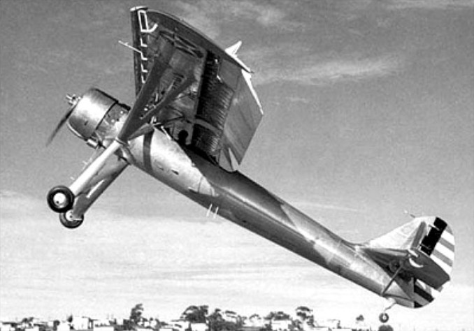
The YO-51 Dragonfly of 1940 was observation monoplane built for the USAAC.
Engine: 1 x 440hp Pratt and Whitney R-985-21 Wasp Junior
Max take-off weight: 1908 kg / 4206 lb
Wingspan: 15.85 m / 52 ft 0 in
Length: 10.51 m / 35 ft 6 in
Max. speed: 208 km/h / 129 mph
Cruise speed: 172 km/h / 107 mph
Crew: 2
Ryan ST / PT-22 / STM / NR-1
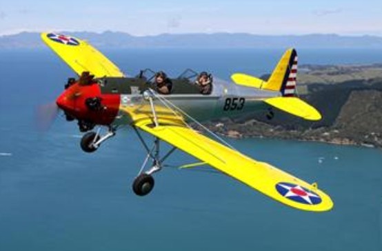
The Ryan ST as had been built in strict accordance with military requirements
With Stearman and Vultee, Ryan was one of three companies selected in 1940 to produce primary trainers for the USAAC’s great expansion of the period, and its initial type was the PT-16 modelled on the civil STA with wheel spats/leg fairings, a wire-braced low-set monoplane wing, and the 93-kW (125-hp) Menasco L-365-1 inline. The Army tested it as the XPT-16. Its performance won a 15-plane service evaluation order, these to be designated YPT-16s.
In the redesign for the YPT-16s, the basic and familiar ST airframe underwent its first external appearance change. The cockpit openings were cut larger, down to meet the channel stiffeners. Addition of a turnover mast at the front cockpit windshield, A Bendix hand-cranked direct drive inertia engine starter, toe brakes and parking brake completed the redesign and met the immediate military specifications. This was the first low-wing trainer to convince the Army to break away from their 30-year precedent of biplanes being used for initial instruction of aviation cadets.
The 16 prototype and trials aircraft were followed by 40 improved PT-20s. Adoption of the 94-kW (132-hp) Kinner R-440-3 radial with a stronger structure led to the PT-21, of which 100 were produced ; re-engining of older aircraft with the R-440-1 produced the PT-16A and PT-20A.
Next came the PT-22 Recruit with the 119-kW (160-hp) Kinner R-540-1 radial, swept back wings, and the 1,023 army aircraft were complemented by 100 naval equivalents designated NR.
The PT 22 was first ordered by the U.S. Army in 1941, and deliveries commenced the same year. The PT-22 was somewhat different to meet military requirements for ease of accessibility to both cockpits with a parachute. The designations PT-22A and PT-22B were applied respectively to 25 aircraft taken over from a Dutch order in 1942, and to 250 PT-22s retrofitted with the R-540-3 radial. The PT-22 was known post WW2 as the civil ST-3-KR.
In the mid ‘thirties, Ryan offered a single-seat armed version of its tandem two-seat STM primary trainer, which, in turn, had been derived from the S-T initially flown on 8 June 1934. Dubbed STA-Special, the single-seater was powered by a 150hp Menasco C4S air-cooled engine, and a second batch of six ordered in December 1938 for the Guatemalan Cuerpo de Aviacion Militar were each fitted with two 7.7mm wing-mounted guns and referred to as light fighters.
The first of the STM-2s were ordered to be equipped with Menasco C-4S “Pirate” supercharged 150hp engines.
The first group of STM-2s was shipped to the Pilots and Observers School (Army Primary Flying School) at the Kalidjati Air Base to the north of Bandung in Western Java. These ships replaced the Koolhoven FK-51s as basic trainers.
Although training was the main duty of the Ryans, when the war got hot in the area, they were constantly being dispersed and used in other roles. The airplanes were pressed into service as reconnaissance aircraft and to supply remote outposts or patrol ships. It was not unusual for the pilots to strap a five-gallon fuel tank in the front cockpit and go out on a long coastal patrol. When the fuel became low the pilot would land at a convenient clearing, refuel the aircraft and continue his flight. During air raids the Ryans would be hidden under palm leaves.
There are a number of reports involving the agile Ryans serving with the Dutch colonial military services. Several were caught or chased by Japanese aircraft while on training or reconnaissance flights; some managed to get back to their base safely, while others were shot down. During another attack the aviators were given orders to fly at a very high altitude in order to report Japanese airplanes approaching the airfield. At times the Ryans engaged in dogfights with the Zeros. The Ryan showed such maneuverability that it did a fair job of staying out of the firing range of the Japanese airplane. One Ryan had an aileron shot off and still the pilot was able to set the airplane down safely.
ST
Engine: Menasco B4, 95 hp
STM S2
Engine: Menasco C-4S, 150 hp
Propeller: Sensenich wooden, fixed pitch
Fuel: Aviation Gasoline 100 Octane
Wingspan: 29′ 11″ / 9.12 m
Length: 21′ 5″ / 6.54 m
Wing Area: 124.0 sq. ft / 11.52 sq. m
Height: 6′ 11″ / 2.11 m
Empty: 1,083 lb / 491 kg
Maximum Takeoff weight: 1,600 lb / 726 kg
Armament: Nil
Maximum Speed: 123 knots / 141 mph / 228 km/h
Cruise Speed: 111 knots / 128 mph / 206 km/h
Loading: +/- 10G
STA
Engine: Menasco C4
STA-Special
Engine: Supercharged Menasco, 150 hp
ST-R
Engine: Menasco C-4/D-4, 125 hp
HP range: 125-160
Height: 6.9 ft
Length: 21.5 ft
Wing span: 30 ft
Wing area: 124 sq.ft
Fuel cap: 24 USG
Weight empty: 1030 lb
Gross: 1575 lb
Speed max: 140 mph
Cruise: 120 mph
Range: 350 sm
Stall: 42 mph
ROC: 850 fpm
Take-off dist: 525 ft
Landing dist: 1000 ft
Service ceiling: 17,500 ft
Seats: 2
Landing gear: tail wheel
ST3KR / PT-21-RY
Engine: Kinner
PT-16
Powerplant: l x Menasco L-365-1, 93kW (125 hp)
Span: 9.14m (30ft )
Length: 6.55m (21 ft 6in)
Max TO weight: 726 kg (1,600 lb)
Max speed: 128 mph at sea level
Operational range: 350 miles
Armament: none
PT-22 Recruit
Engine: Kinner R-540 1 5 cylinder radial, 540ci, 160 hp
Empty wt: 1316 lb
MAUW: 1860 lb
Fuel cap: 20 Imp Gal
Cruise approx: 105 mph
Loading: +/- 10G
Stall: 62-64 mph
NR-1
Engine: Kinner R-440, 132 hp
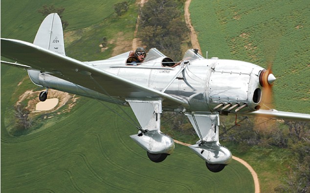
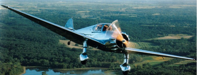
Ryan SC
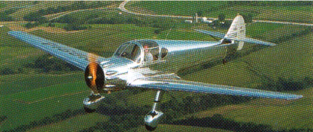
Only 12 Ryan SC-W were built.
Ryan NYP / Spirit of St. Louis
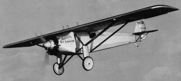
Early in 1927 Charles A. Lindbergh obtained the backing of several St. Louis men to compete for the $25,000 prize offered by Raymond Orteig in 1919 for the first non-stop flight between New York City and Paris. In February of that year Lindbergh placed an order with Ryan Airlines in San Diego for an aircraft with specifications necessary to make the flight.
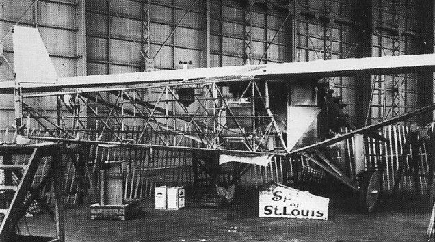
Development began based on a standard Ryan M-2, with Donald A. Hall as principal designer, under the direct supervision of Charles Lindbergh. Certain modifications to the basic high-wing, strut-braced monoplane design had to be made because of the nature of the flight. The wingspan was increased by 10 feet, the ribs had to be spaced 11 in. apart instead of the usual 14 15 in, and the structural members of the fuselage and wing cellule were redesigned to accommodate the greater fuel load (around 2,750 lb). Plywood was fitted along the leading edge of the wings. The fuselage design followed that of a standard M-2 except that it was lengthened 2 feet and streamlined, with no “step” for a windscreen. The cockpit was moved further to the rear for safety and the engine was moved forward for balance, thus permitting the fuel tank to be installed at the center of gravity, completely filling the fore part of the fuselage, up to the roof. The pilot could see forward only by means of a periscope or by turning the aircraft to look out of a side window. A Wright Whirlwind J-5C engine supplied the power. The changes involved only 850 design man hours of work.
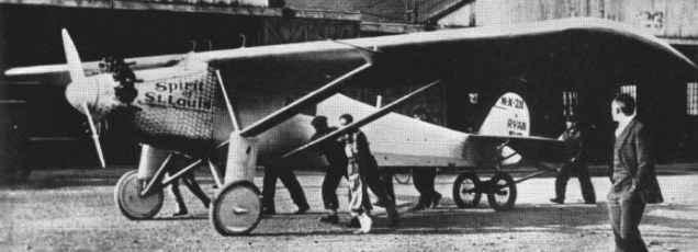
Late in April 1927, the work on the aircraft was completed. It was painted silver and carried registration number N-X-211, which, with all other lettering on the plane, was painted in black. Lindbergh made several test flights, and then flew the aircraft from San Diego to New York on May 10-12, making only one stop, at St. Louis. His flight time of 21 hours, 40 minutes set a new transcontinental record.
Flying the Tallmantz Spirit of Saint Louis
After waiting several days in New York for favourable weather, Lindbergh took off for Paris alone, on the morning of May 20, 1927. Thirty-three hours, 30 minutes, and 3,610 miles later he landed safely at Le Bourget Field, near Paris, where he was greeted by a wildly enthusiastic crowd of 100,000.
No flight in history captured the imagination of the Public more than the solo flight across the Atlantic by 24 year old Charles Lindbergh, from New York to Paris, In May, 1927. The distance of 3,610 miles and the time of 33 hrs 39 min spent alone in the air were formidable enough at an average speed of 107 m.p.h. (171 kph). Added to them was the fact that Lindbergh carried no radio or navigation aids, relying instead on dead reckoning, which brought him within three miles of his planned landfall in Ireland.
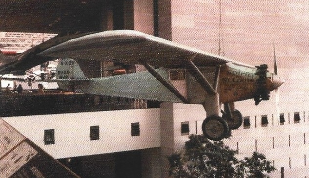
Lindbergh and the Spirit of St Louis returned to the United States aboard the U.S.S. Memphis on June 11. He received tumultuous welcomes in Washington, D.C. and New York City. From July 20 until October 23 of that year he took the famous plane on a tour of the United States. Then, on December 13, he and the Spirit of St. Louis flew nonstop from Washington to Mexico City; through Central America, Colombia, Venezuela, Puerto Rico; and nonstop from Havana to St. Louis. Beginning in Mexico City, flags of the countries he visited were painted on both sides of the cowling. The two tubes beneath the fuselage are flare dispensers that were installed for Lindbergh’s flights to Latin America and the Caribbean.
On April 30, 1928, the Spirit of St. Louis made its final flight – from St. Louis to Washington, D.C where Lindbergh presented the aircraft to the Smithsonian Institution.
Replica:
Tallmantz Aviation Spirit of Saint Louis
Whitney Spirit of Saint Louis
Engine: One Wright J 5C Whirlwind, 200 hp / 165kW
Wing span: 46 ft (14.02 m)
Length: 27 ft 8 in / 8.4328 m
Height: 9 ft 10 in / 2.9992m
Wing area: 29.7 sq.m / 319.69 sq ft
Wing chord: 7 ft
Weight empty: 975 kg / 2150 lb
Weight loaded: 5135lb / 2329.2kg
Fuel capacity : 571 gal / 2160 lt
Cruise speed: 105 mph (170 kph)
Ceiling: 17,500 ft (5,300 m) fully loaded
Max speed: 124 mph
Crew: 1
Ryan M-2
Twenty-one M-2s were built.
