RUSSIA
Established 1992 as a subsidiary of Myasishchev. First flew in 1993 its SL-A light plane, as a derivative of the Interavia SL-90 Leshiy. A-211 is version meeting JAR VLA regulations, while a kit-built version is A-211K.
RUSSIA
Established 1992 as a subsidiary of Myasishchev. First flew in 1993 its SL-A light plane, as a derivative of the Interavia SL-90 Leshiy. A-211 is version meeting JAR VLA regulations, while a kit-built version is A-211K.
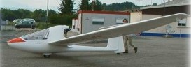
The Exel is a single-seater designed by Claude Noin to offer more performance than the Sirius. It is available as a fast-build kit or ready to fly, and uses composite materials only.
Alpaero pre-manufacture Exel sub-assemblies in their facilities at Gap-Tallard. The most difficult parts, requiring the use of composite materials, large molds, special tools or skills, are all pre-manufactured. The wings can be built easily with traditional wood and fabric techniques, and all other fabrications can be accomplished by the average builder.
The Exel is a very simple motorglider concept with no retractable engine or propeller but with enough soaring performance to fly long distances. The Exel is a light motorglider, and complies with the FAI international requirements for ultralight aircraft. It is marketed as a fast-build kit (around 300 hours), or ready to fly.
The Exel is designed as a small single-place powered sailplane, and uses a “pod and boom” concept with a pusher engine installation, driving an automatic folding propeller. It uses a modern laminar airfoil and a light 2-stroke engine. The pilot enjoys a comfortable reclined position and a perfect visibility inside a roomy cockpit. This motorglider is focused on strength, economy, and performance in thermals, for true recreational soaring. The design is uncomplicated, but incorporates the modern design advantages, like automatic control connections, ballistic rescue parachute and low maintenance thanks to the composite materials.
The landing gear is a fixed monowheel and the tailwheel is integrated into the rudder, making turns easy on the ground. The aircraft can be launched and landed on rough fields. The canopy is a simple and economical flat-wrapped screen. A rescue parachute can be easily installed inside the fuselage.
After testing various powerplants the JPX D-330 two-cylinders engine is used. The JPX D-330 is a flat twin opposed construction, and delivers 20 hp with muffler, electric start and CDI and a TBO (Time Between Overhaul) of 500 hours.
During Summer 2006 an Exel based on the single-cylinder Hirth F-33 was developed. This engine is more powerful (28 hp), and enables more performance in motorized flight (especially climb speed) as well as power-off, thanks to the lower drag of the engine cowling.
The fuselage is molded in two halves of fibreglass/epoxy, with plywood bulkheads. Carbon spar caps and fibreglass wing skins. Lexan/polycarbonate canopy with carbon fibre frame. Fabric-covered rudder.
Flying controls are: pitch control by a conventional elevator, actuated by teleflex. Combined flaps/ailerons (flaperons) for roll control and speed adjustment, with three positions as flaps : -5°, 0°, +5°. Conventional rudder actuated by cables. Airbrakes on upper surface wing. Standard control system (stick and pedals).
The landing gear is monowheel type, fixed. Tail wheel integrated into the rudder for directional control on ground. Small wheels under each wing tip. Drum brake.
A ballistic parachute recovery system (optional).
Engine :
One 14.91 kw (20 hp) JPX D-330 engine with 2.38:1 reduction gear driving a foldable carbon fibre 2-blade propeller at 6,500 rpm. Fuel capacity 19 litres (5.02 US gallons, 4.18 Imp gallons).
or One 20,90 kw (28 ch) Hirth F-33 BS engine driving a foldable carbon fibre 2-blade propeller. Fuel capacity 19 litres (5.02 US gallons, 4.18 Imp gallons).
Wing span: 13.74 m (45.1 ft)
Length overall: 5.90 m (19.3 ft)
Propeller diameter: 1.28 m (4.2 ft)
Wing area: 11.62 sq.m (125.1 sq ft)
Aspect ratio: 16.2:1
Weight empty: 190 kg (432 lb)
Max T-O weight: 310 kg (683 lb)
Max wing loading: 26.67 kg/sq.m (5.46 lb/sq ft)
Cruising speed at 75% power: 120 km/h ( 65 kt, 75 mph)
Max speed: 180 km/h ( 97 kt, 112 mph)
Stalling speed: 64 km/h ( 34 kt, 39 mph)
Max rate of climb: 2.2 m/s (434 ft/mn)
Endurance: 3 hours
T-O run: 150 m (492 ft)
Landing run: 140 m (459 ft)
Best glide ratio: 30:1
Min rate of sink: 0.75 m/s (148 ft/mn)
G limits (operational): + 4.4 / -2.2 G
Seats: one pilot
Noin Aeronautiques Exel
Engine: König 430, 24 hp
Wing span: 12.45 m
Wing area: 10.90 sq.m
MAUW: 290 kg
Empty weight: 165 kg
Fuel capacity: 38 lt
Max speed: 180 kph
Cruise speed: 120 kph
Minimum speed: 55 kph
Climb rate: 3 m/s
Seats: 2
Fuel consumption: 5 lt/hr
Price (1998): 1 744 870 Fttc
Kit price (1998): 55 000 Fttc

Claude Noin designed the Choucas, a side-by-side touring motorglider of tailless configuration, using the same materials as the Sirius. The Choucas (French for “jackdaw”) is a two-place side-by-side (may be flown from either seat) touring motorglider (ULM under French regulations) with front-mounted engine.
Designed as a light, economical and safe touring motorglider, the Choucas is available for amateur construction. It is commercialized as a partial kit for homebuilders, including all the molded composite components. This motorglider has a fast-build fuselage kit.
The Choucas design was initiated in 1994 and the prototype flew for the first time at the end of 1996. The Choucas accumulated over 500 hours of testing in a flight school environment. It has proven itself as an incredibly versatile and easy-to-fly aircraft.
ALPAERO, pre-manufacture Choucas sub-assemblies the facilities at Gap-Tallard, the most difficult parts, requiring the use of composite materials, large molds, special tools or skills, are all pre-manufactured. The wings can be built easily with traditional wood and fabric techniques, and all other fabrications can be accomplished by average builders.
Flying controls: flying wing formula, pitch control by elevators in inboard wing trailing-edge, ailerons outboard, large rudder. Trim tabs on elevators, DSF spoilers/airbrakes on upper surface wing.
Structure: standard fuselage molded in half-shells of carbon fibre/epoxy (with glass fibre/epoxy fuselage available at lower cost with weight penalty), composites wing structure with wooden main spar and glass fibre/epoxy stiffened Styrofoam ribs. The wing uses a modified Abrial/St Cyr airfoil, with 17 % thickness, it can be detached in two parts weighing 55 kg each (on the prototype). Leading edge made of hot wire cut foam laminated with glass fibre and epoxy resin, as an alternative the leading edges can be built as a birch plywood D-section, or molded in carbon fibre. Wing covered with heat-shrink Dacron. Lexan/polycarbonate canopy with carbon fibre frame.
Landing gear: The landing gear is a one-piece composite part, and can be used as a step to access the cockpit.
tailwheel type, fixed. Streamlined fairings on main legs and wheels. Drum brakes.

Engine: One 37.3 kW (50 hp) Rotax 503
Reduction: 2.58:1 gear
Propeller: two-blade carbon fibre, Folding forward optional
Propeller diameter: 1.60 m (5.3 ft)
Wing span: 14.35 m (47.1 ft), optional extension to 15 m
Length overall: 5.35 m (17.6 ft)
Height overall: 1.95 m (6.4 ft)
Wing area: 21.30 sq.m (229.3 sq ft)
Aspect ratio: 9.44:1
Airfoil: modified Abrial/St Cyr 17% airfoil
Fuel capacity: 36 litres (9.5 US gallons, 7.9 Imp gallons) in fuselage tanks
Usable fuel: 35 litres (9.25 US gallons, 7.7 Imp gallons)
Optional fuel: wing tanks (2 x 35 litres) in the Carbon version
Weight empty:
FAI ultralight version : 265 kg (573 lb)
experimental version : 290 kg (639 lb)
Max T-O weight:
FAI ultralight version : 450 kg (992 lb)
experimental version : 510 kg (1124 lb)
Max wing loading :
FAI ultralight version : 21.12 kg/sq.m (4.33 lb/sq ft)
experimental version : 23.94 kg/sq.m (4.90 lb/sq ft)
Cruising speed at 75% power: 130 km/h (70 kt, 81 mph)
Max speed: 180 km/h (97 kt, 112 mph)
Stalling speed: 60 km/h (33 kt, 38 mph)
VNE: 97 kt / 112 mph / 180 kmh
Max rate of climb: 180 m/mn (590 ft/mn)
T-O run: 100 m (328 ft)
Take-off distance (50ft obstacle): 660 ft / 200 m
Landing distance (50ft obstacle): 820 ft / 250 m
Landing run: 150 m (492 ft)
Best glide ratio: with a fixed propeller: 26:1
with a folding propeller: 24:1 (14.35 m version)
26:1 (15 m version + winglets)
Min rate of sink: less than 1.00 m/s (3.28 ft/s) at 80 km/h with a fixed propeller
G limits: + 8 / -4 G
Noin Aeronautiques Choucas
Engine: Rotax 503, 50 hp
Wing span: 14.35 m
Wing area: 21.80 sq.m
MAUW: 450 kg
Empty weight: 260 kg
Fuel capacity: 38 lt
Max speed: 170 kph
Cruise speed: 130 kph
Minimum speed: 60 kph
Climb rate: 4 m/s
Seats: 2
Fuel consumption: 12 lt/hr
Kit price (1998): 55 000 Fttc
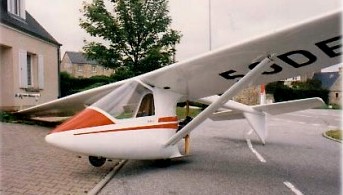
In 1984, Claude Noin created a single-place motorglider powered by a light two-stroke engine : the Sirius. Twenty-two kits were delivered to customers, mainly in France. The Sirius used composite materials for the fuselage, and wood and fabric for the wing, and was powered by a light two-stroke engine, driving a two-blade propeller.
The first prototype flew in August 1984. It used a tube, wood and fabric structure and an 11 m wing.
The production types have a composite fuselage and a longer wing. The design focused on economy and performance at low speeds, features a high wing, a fixed engine and propeller and a fixed gear, with conventional control system with stick and pedals. Pitch control by elevator, including a trim tab, actuated by cables. Ailerons for roll control. DSF Spoilers / Airbrakes on upper surface wing.
The fuselage is molded in two halves of fibreglass/epoxy, with plywood bulkheads and a Lexan/polycarbonate one-piece removable canopy. With a fabric-covered rudder, the composites wing structure has wooden main spar and glass fibre/epoxy stiffened Styrofoam ribs. The leading edge made of hot wire cut foam laminated with glass fibre and epoxy resin. Wings are covered with heat-shrink fabric.
The landing gear is fixed with the main wheel at the C of G location, with drum brakes. Equipped with a nose wheel and small wheels under the tail and under each wing tip.
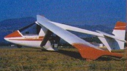
Sirius
Engine: one Koenig 3-cylinders (24 hp)
Sirius C
Engine: One JPX-D-320 (18 hp)
Prop: fixed 2-blade
Fuel capacity 19 litres
Wing span: 13.4 m
Length overall: 5.90 m
Wing area: 14.30 sq.m
Weight empty: 142 kg
Max T-O weight: 270 kg
Max speed: 130 km/h
Stalling speed: 48 km/h
Max rate of climb: 2 m/s (394 ft/mn)
Best glide ratio: 23:1
Min rate of sink: 0.90 m/s
G limits: + 4.4 / -2.2 G
Seats: 1
Noin Aeronautiques Sirius C
Engine: König 430, 24 hp
Wing span: 13.48 m
Wing area: 13.40 sq.m
MAUW: 270 kg
Empty weight: 150 kg
Fuel capacity: 29 lt
Max speed: 130 kph
Cruise speed: 90 kph
Minimum speed: 48 kph
Climb rate: 2 m/s
Seats: 1
Fuel consumption: 5 lt/hr
Plan price (1998): 1929 Fttc
Kit price (1998): 27 386 Fttc
Since 1973, the Noin brothers have been constructing free-flying wings (first sold under the Dahuplane brand).
Much more interested in research than commercial, they have tackled free flight trying to achieve aerodynamically safe aircraft. They are at the origin of the rods for the maintenance of the twist at the end of the wing and of the return halyards to give reflex to the sail.
They designed and built DAHU-PLANE, FLEX-PLANE, STRATUS 1, III B, and IV, CUMULUS 1, II and III, NIMBUS 1 and D 122 (double internal transverse surface) EDELWEISS and the TORNADO.
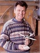
ALPAERO is owned and operated by Claude Noin, a skilled expert in composite and wood structures with over 20 years of design/build experience. Claude Noin is the son of a famous glider pilot, Felicien Noin, who was the first pilot to cross the Alps in a glider. He is able to use the latest technologies as well as the more traditional ones. He founded his firm Noin aeronautique in 1976 and manufactured or repaired several airplanes, motorgliders, boats (single hull or multi-hulls), and hang-gliders. ALPAERO is the trademark used by Noin aeronautique to manufacture and market the Choucas and Exel motorgliders on the international scale. ALPAERO tightly cooperates with experts specialized in aerodynamics and structures, with the stringent JAR-22 as a guideline.
1998:
RN 85
F-05130 Tallard
France
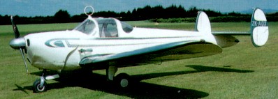
The Ercoupe originated from aeronautical engineer Fred Weick and industrialist Henry Berliner. Henry invited Fred to join his privately owned Engineering Research Corporation (ERCO) to build a commercial version of an earlier Weick design, the W-1A.
The prototype first flew in 1937 as the model 310, and was constructed of metal, with the outer panels of the wings covered with doped fabric to lessen weight. The fuselage aft of the cockpit consisted of four sheets of aluminium that were riveted together on the flat, and wrapped around four bulkheads. The wing structure was equally simple with a single main spar located at 25 percent chord and a small false spar where the ailerons were attached. A sheet metal cover extended round the wing leading edge, back to the aft edge of the spar. This both increased the wings structural rigidity and ensured the crucial part of the aerofoil would maintain shape.
Initial test flights revealed that the basic design was sound but the designers introduced numerous refinements to optimise the characteristics. Refinements were needed in the engine mounting, the up elevator limitation, the fin arrangement and the wing filleting. The production version was assigned ERCO job No 415C and had a 12 inch longer fuselage to increase longitudinal damping.
The aeroplane went into production in 1940 and was available with rudder pedals or with a simplified control without rudder pedals. Equipment offered varied between models, ranging from no radio or gyro instruments to a reasonably complete fit on the later models.
A series of flight tests to trial various fillets and other design features were carried out and in the end the outer portion of the wing did not stall at all, even at full aft elevator. This was due to three factors. Firstly, the wing root so definitely stalled that the spanwise lift distribution was broken down in the centre, and the outer wing panels acted somewhat in the manner of two separate low aspect-ratio airfoils and could go up to a higher angle of attack before stalling. Secondly, the pitching moment of the main wing changed as the centre portion stalled in such a way as to tend to decrease the wings total average angle of attack. Thirdly, the loss of lift in the centre of the wing reduced the downwash on the tail, thus reducing the effectiveness of the elevator. With all three factors at work, even full aft elevator was insufficient to cause the outer portions of the wing, which in this case comprised most of it, to stall. Lateral stability and control were therefore maintained throughout the entire range of speed and angle of attack, at least in power-off flight.
With the 40hp engines these characteristics were maintained, however with the installation of the more powerful 65hp Continental engine modifications were required. The increased slipstream required a further limitation to the up elevator travel to obtain satisfactory power-on stalling characteristics, but then the tail could not be lowered as much as desired during take-off and landing. This problem was overcome by giving the leading edges of the wings a sharply pointed contour for a distance of a few inches adjacent to the fuselage. This caused the air passing over the wing root to break away earlier at high angles of attack even with full power on, thus returning the wings stall characteristics back to those of the earlier model.
One of the more significant design changes during the flight testing stages was the replacement of the conventional single fin with twin fins and resulted from the two-control flight trials.
The undercarriage is designed to allow the aeroplane to be landed crabbed, and the Ercoupe has no flaps.
The US CAA (forerunner of the FAA) purchased the first four aircraft produced and gave them an exhaustive evaluation. A thorough comparison between two groups of trainees with no previous experience was carried out. One group trained in Ercoupes, the other in Piper Cubs. The results were striking, one of the Ercoupe students soloing after only two hours and fifteen minutes of dual instruction. The average time being four and a half hours. The CAA went on to reduce the time required to solo an Ercoupe from the usual eight to five.

Although the first production model of the Ercoupe was ready in 1940, the war blocked further development of the project until the postwar boom, when it looked as though the little company were off and running as it turned out nearly 5,000 aircraft during the first year of production. Production resumed in 1945 with models 414 E, F and G appearing between 1947 and 1949. Finally, in 1951, production ceased when the bottom dropped out.
Forney Manufacturing Company acquired production rights for Engineering and Research Corporation’s Ercoupe 415 two-seat light aircraft in April 1955. The first production Forney F-1 Aircoupe flew on September 1956 and it was later offered as the Fornaire Execta, Explorer, and Expediter.
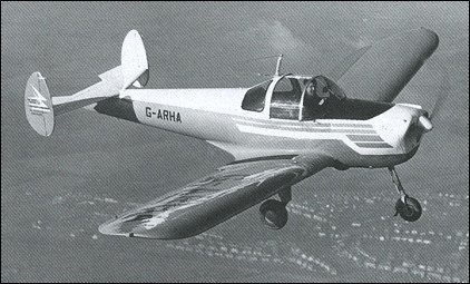
The rights were sold in 1960 to the city of Carlsbad, New Mexico.
Air Products took over production between 1960 and 1962, and then it passed to Alon Aircraft in 1964.
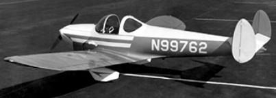
Two ex-Beech employees formed Alon Inc and bought assets, jigs, tools and engineering of the Ercoupe and planned to deliver 30-50 planes in 1964 at $8000 each, with a 100 hp Continental engine.
Alon called its airplane—still virtually unchanged from the original Ercoupe—the Aircoupe A-2. The Alon version did have rudder pedals and a modified landing gear, which on some models is a backward- bending, spring-steel gear leg rather than an oleo strut. The Alon A-2 also featured a blown sliding-bubble canopy instead of the lift-up type fitted on earlier models. Alon Aircoupes had attractive upholstery, and all flight gauges were shock-mounted on a floating subpanel in front of the pilot. Dual toe brakes were standard, operated by a bar running across and above the rudder pedals.
The 1964 A2 Aircoupe was a modernized continuance of Forney Aircoupe with conventional three-control system. 245 were built.
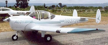
Mooney Aircraft purchased the Aircoupe rights in 1968, changed the double tail to a single tail, and sold the airplane with as the Mooney Cadet. The A-2 Cadet and M.10 Cadet were produced until 1970, when Mooney sold out to Aerostar.
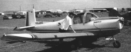
In 1974 Univair Aircraft Corporation purchased the type certificates for the Ercoupe and all its successors from Mooney. They have since been manufacturing nearly all the airframe items necessary to keep any model ‘coupe’ airworthy. From a low point of round 2000 Ercoupes registered as airworthy in 1965, the number has recovered to round 2700 entering the nineties.
Variant:
Thrasher Twin Ercoupe
Erco 415C Ercoupe
1940-41
Engine: Continental A65, 65 hp
Erco 415C Ercoupe
1945-47
Engine: Continental C75-12F, 75 hp
Erco 415E Ercoupe
1947
Engine: Continental C85-12, 85 hp
Empty Weight: 815 lb
Maximum Speed: 144 mph
Service Ceiling: 13,000 ft.
Range: 400 miles
Erco 415F Ercoupe
1947
Engine: Continental C85-12J, 85 hp
Gross weight: 1,400 lb
Empty weight; 838 lb
Fuel capacity: 25 US gal
Top speed: 125 mph
Cruise speed: 110 mph
Stall speed: 47 mph
Initial climb rate: 560 fpm
Service ceiling: 11,000 ft
Range: 430 nm
Seats: 2
Ercoupe 415-G Club Air
1949-51
Engine: Continental C-85-12F, 85
TBO: 1800 hrs
Fuel type: 80 Octane
Propeller: McCauley two-blade, fixed-pitch 71 in
Wingspan: 30 ft
Wing area: 142.6 sq. ft
Overall length: 20 ft. 2 in
Height: 5 ft. 6 in
Gross weight: 1400 lb
Max landing weight: 1400 lb
Empty weight, std: 815 lb
Equipped weight: 857 lb
Useful load, std: 585 lb
Payload, full std. fuel: 416 lb
Landing gear type: Tri/Fixed
Max speed: 99 kt
Cruise speed 75% power: 96 kt
Max range (no reserve): 360 nm
Fuel consumption 75% power: 5.6 USgph
Stall speed: 64 kt
Best rate of climb SL: 1225 fpm
Max operating altitude: 13,500 ft
Takeoff over 50-ft. obstacle: 320 ft
Wheel size, main:6.00 x 6 in
Wheel size, nosewheel: 5.00 x 5 in
Power loading: 16.47 lb/hp
Seating capacity: 2
Cabin doors: 2 sliding windows
Cabin width: 36 in
Cabin height: 48 in
Baggage capacity: 75 lb
Forney F-1 Aircoupe / Execta / Expediter / Explorer
1955-59
Engine: Continental C-90F, 90 hp
Wingspan: 30 ft 0 in / 9.14 m
Length: 20 ft 2 in / 6.15 m
Empty weight: 890 lb / 404 kg
Gross weight: 1,400 lb / 635 kg
Fuel capacity: 25 US gal
Top speed: 129 mph
Max cruise 75%: 105 kt / 121 mph / 195 kph
Cruise speed: 114 mph
Stall speed: 48 mph
Initial climb rate: 640 fpm
Range: 434 nm / 500 mi / 805 km
Service ceiling: 15,500 ft / 4725 m
Takeoff run: 540 ft
Landing roll: 350 ft
Seats: 2
Baggage area: 75 lb / 34 kg
Air Products F-1A Aircoupe
1960-62
Air Products Air-Coupe 415D Club Trainer
Modified F-1A
Alon A-2 AirCoupe
1964-67
Sliding bubble canopy, lower seats
Engine: Continental C-90-16F, 90 hp
Useful load: 520 lb
Max speed: 129 mph
Cruise: 114 mph
Stall: 45 mph
Range: 455 mi
Ceiling: 17,300′
Seats: 2
Mooney A-2A Cadet
1967-68
Cantilever spring steel main wheel legs
Mooney M10 Cadet
1968-69
New rear fuselage, single fin and rudder
Engine: Continental C-90, 90 hp
Gross weight: 1,450 lb
Empty weight: 950 lb
Fuel capacity: 24 US gal
Top speed: 118 mph
Cruise speed: 110 mph
Stall speed: 46 mph
Initial climb rate: 835 fpm
Service ceiling: 12,500 ft
Range: 480 nm
Takeoff distance (50 ft): 953 ft
Landing distance (50 ft): 1,016 ft
Seats: 2
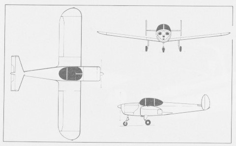

The Pratt & Whitney/Allison 578-DX was an experimental aircraft engine, a hybrid between a turbofan and a turboprop known as a propfan. The 578-DX was developed as a joint venture between Pratt & Whitney and Allison. Unlike the competing General Electric GE-36 UDF, the 578-DX was fairly conventional, having a reduction gearbox between the LP turbine and the propfan blades. First run in 1986, noise considerations, plus a significant reduction in the real cost of aviation fuel, brought the NASA funded program to a halt
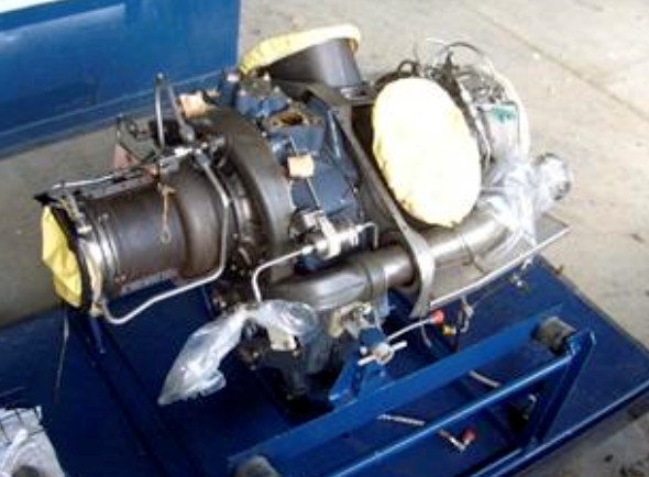
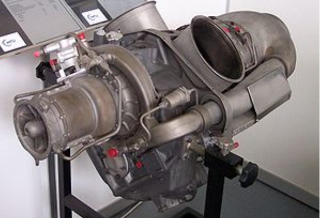
The Allison Model 250, known as the Rolls-Royce M250, (US military designations T63 and T703) is a successful turboshaft engine family, originally developed by the Allison Engine Company in the early 1960s. The Model 250 has been produced by Rolls-Royce since it acquired Allison in 1995.
Allison adopted a reverse airflow engine configuration for the Model 250: although air enters the intake/compression system in the conventional fashion, the compressed air leaving the centrifugal compressor diffuser is ducted rearwards around the turbine system, before being turned through 180 degrees at entry to the combustor; the combustion products expand through the two stage HP turbine, which is connected, via the HP shaft, to the compression system, before expanding through the two stage power turbine; the exhaust gases then turn through 90 degrees to exit the engine in a radial direction; a stub shaft connects the power turbine to a compact reduction gearbox, located inboard, between the centrifugal compressor and the exhaust/power turbine system.
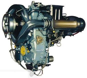
One of the latest versions of the Model 250 is the -C40, which has a centrifugal compressor pulling a pressure ratio of 9.2:1, at an airflow of 6.1 lb/s (2.8 kg/s), and developing, at the shaft, 715 hp (533 kW).
Some of the earlier versions have axial compressor stages mounted on the HP shaft to supercharge a relatively low pressure ratio centrifugal compressor. The -C20R is typical, pulling an overall pressure ratio of 8.0:1, at an airflow of 4.0 lb/s (1.8 kg/s), with a power output, at the shaft, of 450 hp (340 kW).
The Model 250 powers a large number of helicopters, small aircraft and even a motorcycle (MTT Turbine Superbike). As a result, nearly 30,000 Model 250 engines have been produced, making the Model 250 one of the highest-selling engines made by Rolls-Royce.
Variants:
250-B15
250-B15A
250-B15C
250-B17
250-B17B
250-B17C
250-B17D
250-B17F
250-B17F/1
250-B17F/2
250-C18
250-C18A
250-C20
250-C20B
250-C20F
250-C20J
250-C20R
250-C20R/1
250-C20R/2
250-C20R/4
250-C20S
250-C20W
250-C22B
250-C28
250-C28B
250-C28C
250-C30
250-C30G
250-C30G/2
250-C30M
250-C30P
250-C30R
250-C30R/3
250-C30R/3M
250-C30S
250-C30U
250-C34
250-C40B
250-C47B
250-C47E
250-C47M
T63-A-5
T63-A-5A
T63-A-700
T63-A-720
T703-AD-700
Applications:
Fixed-wing
Beechcraft Bonanza {Prop-jet conversions}
Britten-Norman BN-2T Turbine Islander
Extra EA-500
GAF Nomad
Gippsland GA10
Partenavia AP.68TP variants – Spartacus & Viator
Soloy Cessna 206 turbine conversion
Rotary-wing
Agusta A109A
Bell 206B/L/LT
Bell 407
Bell 222SP
Bell 230
Bell 430
Bell OH-58 Kiowa
Bell YOH-4
Boeing AH-6
Cicaré CH-14
Enstrom 480
Eurocopter AS350 Soloy AS350RM AllStar
Eurocopter AS355F
Fairchild Hiller FH-1100
Hughes OH-6 Cayuse
MBB Bo 105
MD Helicopters MD 500
MD Helicopters MD 600
MD Helicopters MH-6 Little Bird
Northrop Grumman MQ-8 Fire Scout
PZL Kania
PZL SW-4
Schweizer 330/330SP
Schweizer S-333
Sikorsky S-76
Kamov Ka-226
Others
Loral GZ-22, non-rigid airship
MTT Turbine Superbike, motorcycle
Specifications:
T63-A-5
Type: Turboshaft
Length: 40.5 in (1,029 mm)
Diameter: 22.5 in (572 mm)
Dry weight: 136 lb (62 kg) dry
Compressor: 6-stage axial + 1-stage Centrifugal compressors
Combustors: Single can combustion chamber
Turbine: 2-stage axial gas generator power turbine + 2-stage axial free-power output turbine
Fuel type: JP-4 Aviation kerosene (alternatively JP-1 or JP-5)
Oil system: pressure spray/splash, dry sump
Maximum power output: 250 hp (190 kW) for Take-off, sea level 59 °F (15 °C)
Overall pressure ratio: 6.2:1
Turbine inlet temperature: 1,805 °F (985 °C)
Specific fuel consumption: 0.77 lb/hp-hr (0.468 kg/kW-hr) at 90% power cruise rating
Power-to-weight ratio: 1.838 hp/lb (3.022 kW/kg)
C20B/F/J
Weight: 73 kg
Airflow rate: 1.230 kg/s
Pressure ratio: 6.2 :1
Takeoff power: 420 WPS
Continuous power: 317 WPS
Height: 571 mm
Width: 483 mm
Length: 986 mm
C20R
Weight: 78 kg
Airflow rate: 1.733 kg/s
Pressure ratio: 7.9 :1
Takeoff power: 450 WPS
Continuous power: 380 WPS
Height: 589 mm
Width: 528 mm
Length: 986 mm
B17D
Weight: 90 kg
Airflow rate: 1.624 kg/s
Pressure ratio: 7.2 :1
Takeoff power: 420 WPS
Continuous power: 370 WPS
B17F
Weight: 93 kg
Airflow rate: 1.733 kg/s
Pressure ratio: 7.9 :1
Takeoff power: 450 WPS
Continuous power: 380 WPS
C30M
Weight: 115 kg
Airflow rate: 2.54 kg/s
Pressure ratio: 8.6 :1
Takeoff power: 650 WPS
Continuous power: 540 WPS
Height: 638 mm
Width: 555 mm
Length: 1041 mm
C30S
Weight: 114 kg
Airflow rate: 254 kg/s
Pressure ratio: 8.6 :1
Takeoff power: 650 WPS
Continuous power: 501 WPS
Height: 638 mm
Width: 555 mm
Length: 1041 mm
C30P
Weight: 114 kg
Airflow rate: 2.54 kg/s
Pressure ratio: 8.6 :1
Takeoff power: 650 WPS
Continuous power: 501 WPS
Height: 638 mm
Width: 555 mm
Length: 1041 mm
C40B
Weight: 127 kg
Airflow rate: 2.77 kg/s
Pressure ratio: 9.2 :1
Takeoff power: 715 WPS
Continuous power: 613 WPS
Height: 638 mm
Width: 555 mm
Length: 1040 mm
C47B/M
Weight: 124 kg
Airflow rate: 2.77 kg/s
Pressure ratio: 9.2 :1
Takeoff power: 650 WPS
Continuous power: 600 WPS
Height: 638 mm
Width: 555 mm
Length: 1040 mm
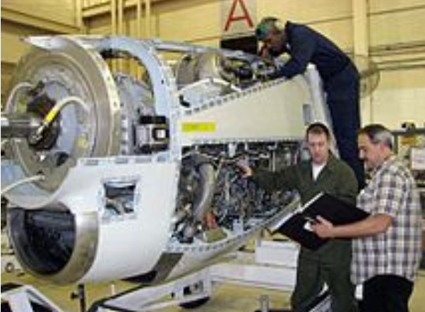
The Allison T56 is a single shaft, modular design military turboprop with a 14 stage axial flow compressor driven by a four stage turbine. It was originally developed by the Allison Engine Company for the Lockheed C-130 transportentering production in 1954 but was produced under Rolls-Royce which acquired Allison in 1995. The commercial version is designated 501-D. With an unusually long and numerous production run, over 18,000 engines have been produced since 1954, logging over 200 million flying hours.
The engine evolved from Allison’s previous T38 series. It was first flown in the nose of a B-17 test-bed aircraft in 1954. Originally fitted to the Lockheed C-130 Hercules, the T56 was also installed on the P-3 and E-2/C-2 aircraft, as well as civilian airliners such as the Lockheed Electra and Convair 580. A shipboard version, the 501K engine, is used to generate electrical power for all U.S. Navy cruisers and destroyers currently in commission.
More than 18,000 have been built.
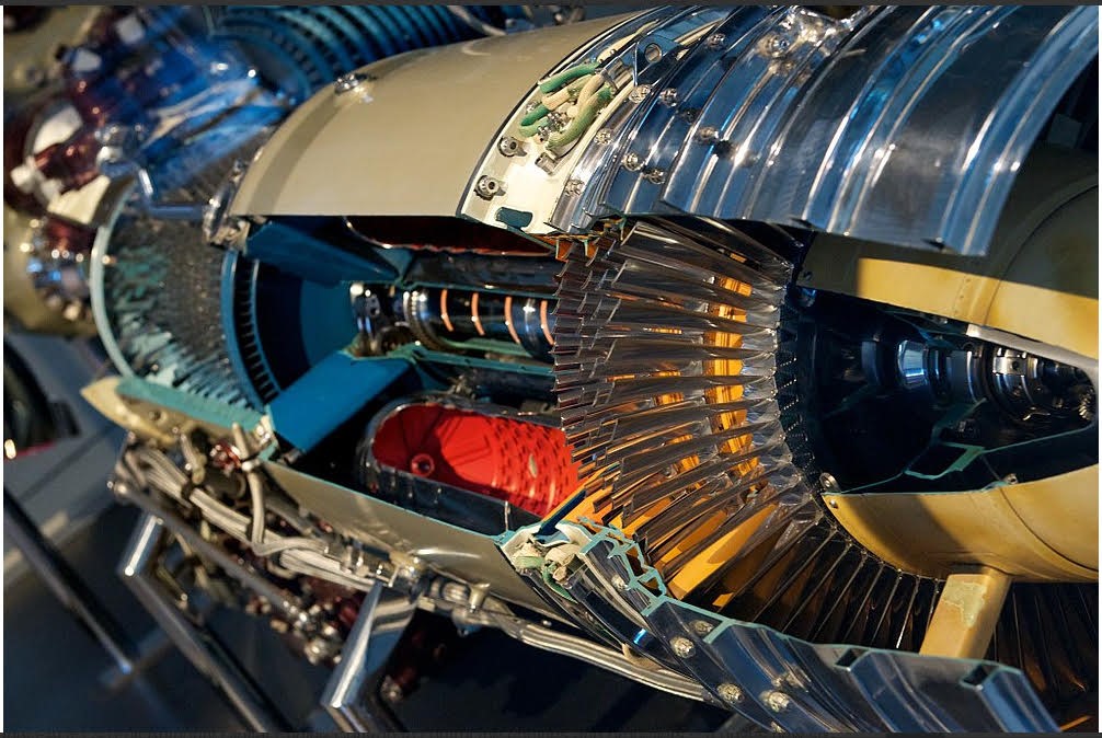
In the Lockheed Martin C-130J Super Hercules which first flew in 1996, the T56 is replaced by the Rolls-Royce AE 2100, which uses dual FADECs (Full Authority Digital Engine Control) to control the engines and propellers. It drives new six-bladed scimitar propellers from Dowty Rotol.
Variants:
501-D13
(Series I) Lockheed L-188 Electra and Convair CV-580 (Replacing P & W R-2800) starting December 1957
501-D13A
(Series I) Similar to -D13
501-D13D
(Series I) Similar to -D13
501-D13H
(Series I) Similar to -D13
501-D22
(Series II) Lockheed L-100 Hercules
501-D36A
(Series II) (non-type certified)
501-D22A
(Series III)
501-D22C
(Series III) similar to -D22A
501-D22G
(Series III) similar to -D22A
501-M62
Company designation for the T701-AD-700 Turbo-shaft engine to power the Boeing-Vertol XCH-62 Heavy-lift helicopter.
T56-A-7
(Series I)
T56-A-8
(Series I)
T56-A-9
(Series I)
T56-A-9D
(Series I) Lockheed C-130A Hercules Starting December 1956 and on all Grumman E-2A Hawkeyes from 1960
T56-A-9E
(Series I) Similar to -A-9D
T56-A-10W
(Series I) with water injection
T56-A-7A
(Series II) Lockheed C-130B Hercules Starting May 1959
T56-A-7B
(Series II) Similar to -A-7A
T56-A-10WA
(Series II)
T56-A-14
(Series III) Lockheed/Kawasaki P-3/EP-3/WP-3/AP-3/CP-140 Aurora from August 1962
T56-A-15
(Series III) Lockheed C-130H Hercules from June 1974
T56-A-16
(Series III)
T56-A-425
(Series III) Grumman C-2A Greyhound from June 1974
T56-A-14+
(Series III.V) Fuel efficiency and reliability upgrade
T56-A-15+
(Series III.V)
T56-A-16+
(Series III.V)
T56-A-425+
(Series III.V) Northrop Grumman E-2 Hawkeye from August 2011
T56-A-427
(Series IV) Northrop Grumman E-2 Hawkeye upgrades from 1972
T56-A-427A
(Series IV) similar to the -A-427
T701-AD-700
(501-M62) Turbo-shaft engine for the Boeing-Vertol XCH-62 Heavy-lift helicopter.
Applications:
Lockheed Martin C-130 Hercules
Lockheed P-3 Orion
Northrop Grumman E-2 Hawkeye
Grumman C-2A Greyhound
Convair 580 and Convair 5800
Lockheed L100 Hercules
Lockheed L-188 Electra
Lockheed R7V-2 Constellation – Done for testing the model 501D for use on the L-188 Electra. Was nicknamed “Elation” during testing.
Aero Spacelines Super Guppy
Specifications:
T56 Series IV
Type: Turboprop
Length: 146.1 in (3,711 mm)
Diameter: 27 in (690 mm)
Dry weight: 1,940 lb (880 kg)
Compressor: 14 stage axial flow
Combustors: 6 cylindrical flow-through
Turbine: 4 stage
Fuel type: JP8 2412 pounds per hour
Maximum power output: 4,350 shp (3,915 kW) limited to 4,100
Turbine inlet temperature: 860°C
Power-to-weight ratio: 2.75:1 (shp/lb)
The Allison Engine Company has its roots in September 1904, when the Concentrated Acetylene Company was founded by James Allison, Percy C. ‘Fred’ Avery and Carl G. Fisher. Avery was the holder of the patent for the product. This company was the predecessor of the Prest-O-Lite Company, a manufacturer of acetylene headlights. An explosion at the acetylene gas works in downtown Indianapolis caused the company to relocate out of town, near the race track in Speedway, Indiana. Allison and Fisher raced automobiles at that track, each owning a race car team. This hobby resulted in Allison building a shop at the track in Speedway where he maintained his fleet of race cars. This shop became the site for Allison Plant #1. Fisher and Allison sold their interest in Prest-O-Lite to Union Carbide for $9,000,000.
Allison started as an engine and car “hot rodding” company servicing the Indianapolis Motor Speedway in Indianapolis. James Allison was the owner of the Indianapolis Speedway Team Company, a race car business in Indianapolis, Indiana. While it was originally known as the Indianapolis Speedway Team Company, its name changed numerous times, first to the Allison Speedway Team Company, then the Allison Experimental Company and last as the Allison Engineering Company before becoming a division of General Motors.
The company’s only regular production item was a patented steel-backed lead bearing which was used in various high performance engines. It also built various drive shafts, extensions and gear chains for high power engines, on demand. Later its main business was the conversion of older Liberty engines to more powerful models, both for aircraft and marine use.
Allison needed a place where his race car engines could be modified and repaired. On January 1, 1917 Allison moved into a building at what in later years was to become the Indianapolis Motor Speedway. Along with the move, Allison hired engineer Norman H. Gillman, from a competing race team as his Chief Engineer.
Allison moved to Florida to invest in real estate after the war, leaving Gillman in charge. Allison did not want the company to wither, so he asked Gillman to build a V-12 marine engine worthy of the Allison name. Gillman then proceeded to build an engine that relied on what was learned from building and modifying the Liberty engine.
Allison’s company was sold to Captain Eddie Rickenbacker in 1927 for $700,000 after Allison moved to Florida. In 1929, shortly after the death of James Allison, the company was purchased by the Fisher brothers, who instructed it to use the cylinder design for a six-cylinder engine for a “family aircraft”. Before work on this design had progressed very far, Fisher sold the company to General Motors, who owned it for most of its history, which ended development due to financial pressures of the Great Depression. Nevertheless Gilman pressed ahead with the cylinder design, building a “paper project” V-12 engine. The Army was once again uninterested, but instead suggested Allison try selling it to the United States Navy. The Navy agreed to fund development of A and B models to a very limited degree for its airships, until the crash of the USS Macon in 1935, when the Navy’s need for a 1,000 hp (750 kW) engine disappeared.
The very first V-1710 was purchased by the US Navy as their GV-1710-2, and appears to have had an Allison serial of number 1, suggesting that they restarted numbering for the V-1710. The first V-1710 engine purchased by the USAAC was AAC 33-42, Allison SN 2, the XV-1710-1, while SN’s 3, 4, 5 were V-1710-4 engines for USN airships, followed by a batch of 11 Air Corps engines purchased with FY-1934 funds (34-4 through 34-14) that covered Allison serials 6 through 16. After these the production totaled over 70,000 V-1710s.
By this point the Army had become more interested in the design, and asked Allison to continue with a new “C” model. They had few funds of their own to invest, and Allison supported much of the development out of their own pocket. The V-1710-C first flew on 14 December 1936 in the Consolidated A-11A testbed. The V-1710-C6 successfully completed the Army 150 hour Type Test on 23 April 1937, at 1,000 hp (750 kW), the first engine of any type to do so. By this point all of the other Army engine projects had been cancelled or withdrawn, leaving the V-1710 as the only modern design available. It was soon found as the primary powerplant of the new generation of United States Army Air Corps (USAAC) fighters, the P-38 Lightning, P-39 Airacobra and P-40 Warhawk.
The Army had been leaning heavily towards exhaust-driven turbochargers instead of the more common mechanically driven superchargers, feeling that their added performance more than made up for the added complexity. Thus little effort was invested in equipping the V-1710 with a reasonable supercharger, and when placed in aircraft designs like the P-39 or P-40 which lacked the room for a turbo the engine suffered tremendously at higher altitudes. It was for this reason in particular that the V-1710 was later removed from the P-51 Mustang and replaced with the Rolls-Royce Merlin.
With the need for the V-1710 winding down at the end of the war, Allison found itself with a massive production infrastructure that was no longer needed. For this reason, in 1947, the Army decided to take General Electric’s versions of Frank Whittle’s jet engines and give them to Allison to produce instead. The main production model was GE’s 4,000 lbf (18 kN) I-40, produced as the Allison J33. By the time production ended in 1955, Allison had produced over 7,000 J33s.
Allison also took over GE’s axial flow engine design, becoming the Allison J35. The J35 was the primary powerplant for the F-84 Thunderjet and F-89 Scorpion, as well as appearing on numerous prototype designs. The J35 also finished production in 1955, by which point over 14,000 had been delivered.
Allison also started the development of a series of turboprop engines for the U.S. Navy, starting with the T38 and a “twinned” version as the T40. The Navy was interested only in the T40, but the complexities of the driveshaft arrangement doomed the engine and the project was eventually cancelled. Allison tried again with the T56, basically an enlarged T38 with the power of the T40, and was eventually rewarded when this engine was selected to power the C-130 Hercules.
Over the years a family of engines, based on the T56 basic configuration has been developed, culminating in the T406/Allison AE1107 turboshaft for the V-22 Osprey, the Allison AE2100 turboprop, used on newer models of the C-130 and the Allison/Rolls-Royce AE 3007 turbofan which propels many commuter aircraft, such as the Embraer ERJ 135 family.
One of Allison’s most successful projects is the Model 250 turboshaft/turboprop engine family, which was started by the company in the early 60s, when helicopters started to be powered by turbine, rather than reciprocating, engines.
In the mid-1970s the Allison Division of General Motors Corporation in Detroit designed ceramic components into the Allison GT 404-4 truck engine. Allison continued to work with General Motors on development of ceramic-turbine powered engines until the early 1990s. During their work they were able to engineer fairly stable automobile engines that were capable of burning a variety of fuels including (but not limited to) gasoline, diesel, kerosene, alcohol, vegetable oil, and coal powder.
In the 1980s Allison collaborated with Pratt & Whitney on demonstrating the 578-DX propfan. Unlike the competing General Electric GE-36 UDF, the 578-DX was fairly conventional, having a reduction gearbox between the LP turbine and the propfan blades. Noise considerations, plus a significant reduction in the real cost of aviation fuel, brought the NASA funded program to a halt.
LHTEC (Light Helicopter Turbine Engine Company) is a joint venture between Rolls-Royce and Honeywell founded in 1985. The company was originally a partnership between the Allison Engine Company and AlliedSignal Aerospace. In 1995 Rolls-Royce acquired Allison, and AlliedSignal merged with Honeywell in 1999, and adopted its name.
In 1995, Allison tested a prototype lift fan for the Joint Strike Fighter Program and a LiftFan nozzle was tested in 1997 at NASA’s Lewis facility. By 1997, a complete prototype had been demonstratedby the Rolls-Royce owned but American controlled Allison Advanced Development Company.
In 1992 GM tried to sell Allison to concentrate on repairing automobile market share. Rolls-Royce attempted to buy the company in 1993, but GM opted for a management buyout instead for $370 million.
In 1995 authorities approved (with restrictions on JSF) the purchase of Allison by Rolls-Royce to become a subsidiary. The price was $525 million. In the year 2000, some of these restrictions were alleviated, and in 2001 the US government chose the F-35 with Allison/RR technology.

