Nanchang CJ-6 / Shengyang Chujiao 6 / BT-6

In the early 1950s, the primary trainer aircraft used by the Air Force was the Soviet Yak-18. At that time, the Nanchang Aircraft Factory was able to independently produce the aircraft in accordance with Soviet drawings. The steel frame of the Yak 18 type of steel frame, the structure of the outer cover was relatively backward, and the airborne power supply was insufficient. Designers such as Xu Shunshou believe that it is no longer necessary to introduce the improved Yak 18A, and it is entirely possible to independently develop a primary trainer based on domestic technical strength.

Nanchang CJ-6 Article

In July 1957, the Chujiao 6 design was begun, and the prototype flew for the first time in August of the following year. On January 5, 1962, Chujiao-6 completed the design finalization. After the successful test flight of the Chujiao 6 in Nanchang, many people in the aviation industry system and the air force still believed in the Soviet aircraft and advocated the production of the Yak 18A. Until a new leader of the Aviation Industry System took office, he decided to continue to improve the elementary trainer 6.

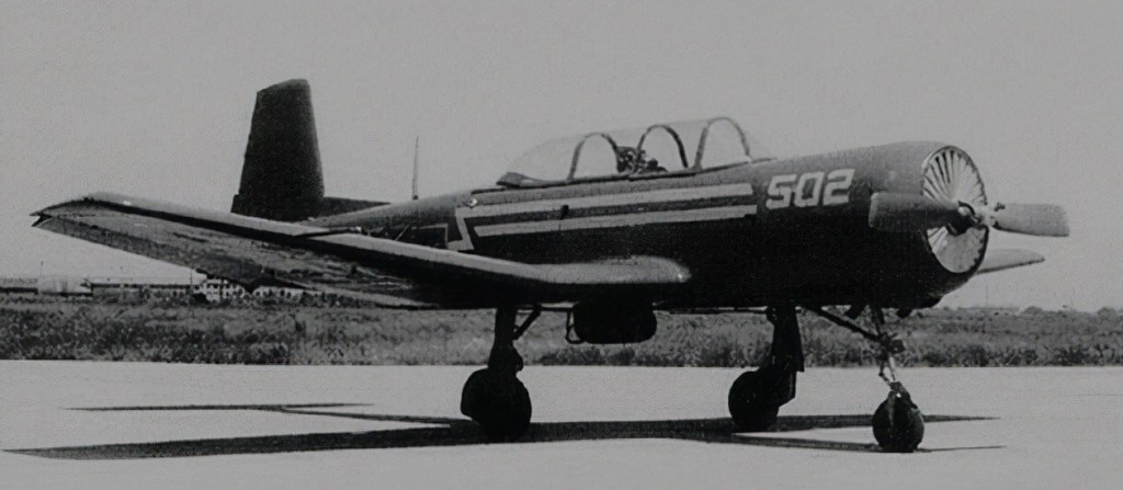
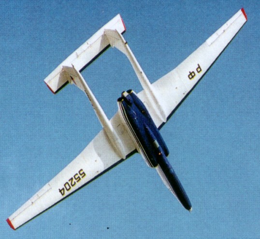
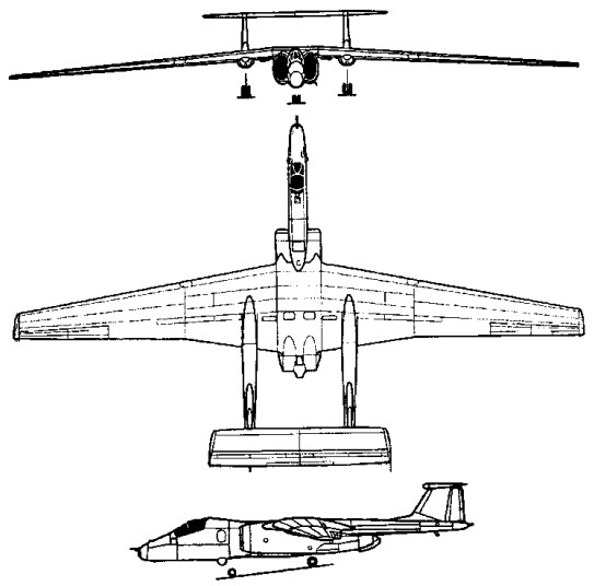
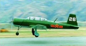
The body of Chujiao 6 adopts an all-metal thin-skinned shell structure, which is similar to the Yak 18 in appearance. The actual fuselage, wings and front three-point landing gear are all new designs.

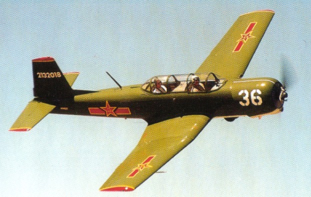
A Chinese derivative of the Yak-18, and development of the CJ-5, the CJ-6 is aerobatic, with a fully retracting undercarriage.

A military primary trainer, approximately 2000 were built for the Peoples Liberation Army Air Force from 1962. It has also served with the air forces of Albania, Bangladesh, Cambodia, Tanzania and Zambia.

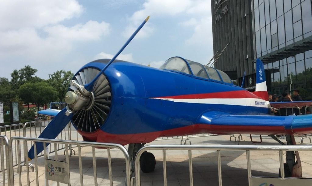
The improved CJ-6A still being built in the late 1990s in very low volume for the same radial piston-engined primary training role.

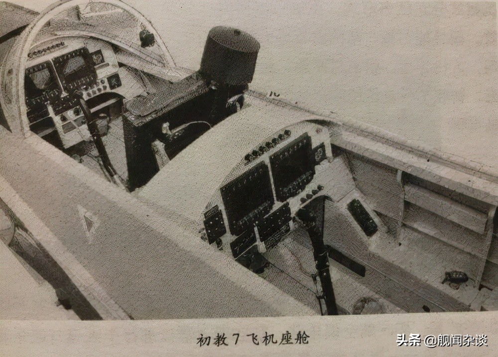
Elementary Education 6 also has many shortcomings: the onboard equipment is backward, there is no ejection rescue system, the cockpit is not sealed, the noise is loud, and the operating environment is not good in cold weather. Therefore, the domestic development of a new generation of primary trainers has been brewing since the 1990s. In August 2007, Chujiao 7 was formally established, and the first flight was successful in 2010, and it was publicly unveiled at the Zhuhai Air Show.

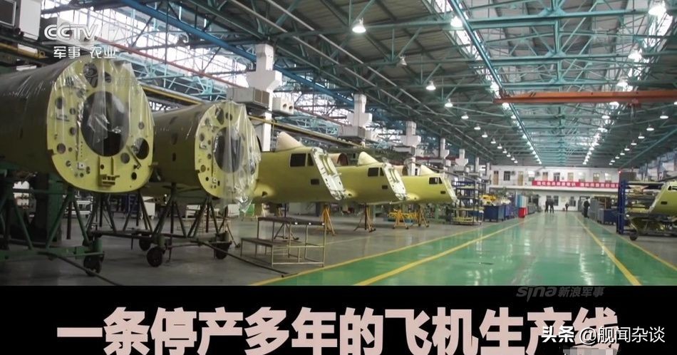
In 2015, Hongdu Company officially began to resume primary education 6. It can be seen in the news that there are a large number of newly manufactured Chujia 6 in the Hongdu Aviation Workshop. The production number of the fuselage shows that the output is at least dozens of aircraft. The Air Force has resumed bulk purchase of Chujia 6, and Chujia 7 is completely yellow.

Gallery

CJ-6A
Engine: Huosai-6 9 cyl radial, 285 hp
ROC: 1500 fpm
Cruise: 135 kt
Length: 8.46m
Wingspan: 10.22m
Wing area: 17sq.m
Loading: +6/-3G
Empty wt: 1095 kg
MAUW: 1400 kg
Max speed: 350 kph
Range: 625 km
Endurance: 2.5 hr

Nanchang Aircraft Manufacturing Company

Formed in 1951; produced a variant of the Soviet Yakovlev Yak-18 trainer known locally as the CJ-5, the improved CJ-6A still being built in the late 1990s in very low volume for the same radial piston-engined primary training role. Also co-produced (with Shenyang) a Soviet MiG-19 fighter variant known as the J-6, and license-built the Antonov An-2 general-purpose biplane as the Y5 before this was taken over by the Shijiazhuang Aircraft Manufacturing Corporation. Very important program to develop the Q-5 dedicated attack aircraft from J-6 technology was begun at Shenyang in 1958 but transferred to Nanchang.

June 1965 saw first flight of a Q-5 Fantan prototype, featuring an area ruled fuselage for minimum transonic drag, cockpit armour protection, a “solid” nose and a weapon bay (for early test and production aircraft, but omitted from improved production versions). Entered Chinese service in 1970 and also exported from 1983 as upgraded A-5. Also developed the N-5A agricultural aircraft (first flown December 1989) and partnered Pakistan Aeronautical Complex in development of the K-8 Karakorum jet trainer (first flown November 1990). Name changed to Hongdu Aviation Industry (Group) Corporation Ltd. in March 1998.

Myasishchev M-201-M

One other version of the M-4 ‘Bison’ is known, a test-bed aircraft powered by four D-15 turbojet engines each of 13000kg thrust and designated 201-M.

This was used in September 1959 to establish a number of payload-to-height records by lifting a payload of 10,000 kg (22,046 lb) to 50,253 ft (15,317 m) and the weight of 55,220 kg (121,480 lb) to 2000 m (6,561 ft).

Myasishchev M-17 Stratosfera / M-55 Geophysics

M-55 Mystic-B

Originally identified in 1982 by US reconnaissance satellites as the ‘Ram-M’ single-seat high-altitude reconnaissance aircraft, and later codenamed ‘Mystic’ by NATO, the twin-boom straight-wing jet, was publicised as a high-altitude research aircraft able to carry around 1500kg of sensors, existing in two versions.

The first of two prototype aircraft, designated M-17 Stratosfera (‘Mystic-A’), first flew in 1988 and are powered by a single 68.6kN thrust Rybinsk RD-36-51V turbojet developed from the Tu-144 SST powerplant.

The M-55 Geofizika (‘Mystic-B’), has two 49kN thrust Perm/Soloviev PS-30-V12 turbojets mounted side-by-side behind a raised cockpit installed in a longer nose, together with a reduced span wing.
The M-55 ‘Mystic-B’ differs from the first M-17 Stratosfera in having a longer jetpipe, shorter engine intakes, a reprofiled nose and an undernose FLIR turret.

The role of the ‘Mystic-B’ is described as environmental sampling missions or high-altitude research and endurance in this role is claimed as over 4 hours loiter capability at 20000m. A further variant of the M-55 is reported to be under development with wingroot mounted engines in stalled in a conventional fuselage carrying a sweptback tail unit.

Two ‘Mystic-A’ prototypes were followed by two ‘Mystic-B’ and two pre-production ‘Mystic-Bs’ were flying by 1992.

M-55 Mystic-B

Gallery

Engines: 2 x Soloviev PS-30-V12, 49kN
Wingspan: 37.47 m / 122 ft 11 in
Length: 22.87 m / 75 ft 0 in
Height: 4.83 m / 15 ft 10 in
Cruise speed: 750 km/h / 466 mph
Ceiling: 21000 m / 68900 ft
Crew: 1

Myasishchev M-17 / M-55 Geophysics

Myasishchev VM-T Atlant

After directing CAHI (TsAGI) from 1960, Myasishchev returned to OKB No 23 in early 1978 in order to study how a 3M strategic bomber might be modified to convey large space launchers and similar payloads. In particular an aircraft was needed to transport to the Baikonur launch site four kinds of load: the nose of the Energiya launcher; the second portion of Energiya; the Energiya tank; and the Buran spacecraft, with vertical tail and engines removed. These loads typically weighed 40 tonnes and had a diameter of 8m. Myasishchev had previously calculated that such loads could be flown mounted above a modified 3M bomber. He died on 14th October 1978, the programme being continued by V Fedotov. While design went ahead, three 3M tanker aircraft were taken to SibNIA (the Siberian State Research Instiutute named for S.A.Chaplygin) and put through a detailed structural audit preparatory to grafting on a new rear fuselage and tail, and mountings for the external payload. The modified aircraft were designated 3M-T. All were rebuilt with zero-life airframes and new engines, but initially without payload attachments. One was static-tested at CAHI while the other two were completed and flown, tne first on 29th April 1981. After a brief flight-test programme they were equipped to carry pick-a-back payloads, and in Myasishchev’s honour redesignated VM-T Atlant. The first flight with a payload was made by A.Kucherenko and crew on 6th January 1982. Subsequently the two Atlant aircraft carried more than 150 payloads to Baikonur.

The most obvious modification of these aircraft was that the rear fuselage was replaced by a new structure 7m longer and with an upward tilt, carrying a completely new tail. This comprised modified tailplanes and elevators with pronounced dihedral carrying inward- sloping fins and rudders of almost perfectly rectangular shape, with increased total area and outside the turbulent wake from any of the envisaged payloads. Less obvious was the fact that, even though the maximum take-off weight was less than that for the bomber versions, the airframe was strengthened throughout.

As time between overhauls was not of great importance the original four VD-7B engines were replaced by the VD-7M. These were RD-7M-2 engines, originally built for the Tu-22 supersonic bomber with afterburners and variable nozzles, which had had the afterburner replaced by a plain jetpipe and fixed-area nozzle. Thrust was 11,000kg. These were in turn replaced by the VD-7D, rated at 10,750kg. Each aircraft was fitted with 14 attachment points above the fuselage and on lateral rear-fuselage blisters for the four different kinds of supporting structure, each being specially tailored to its payload. They were also equipped with a modified flight-control and autopilot system. The forward fuselage was furnished with work stations for a crew of six.

The aircraft were given civilian paint schemes, one being registered RF-01502 and the other being RF-01402 and fitted with a flight-refuelling probe. To support their missions the PKU-50 loading and unloading facility was constructed at spacecraft factories, including NPO Energiya at Moscow Khimki, and at the Baikonur Cosmodrome. These incorporated a giant gantry for carefully placing the payloads on the carrier aircraft. Despite the turbulent aerodynamics downstream of the external payloads, this dramatic reconstruction proved completely successful.

Max take-off weight: 136400 kg / 300712 lb
Max. speed: 600 km/h / 373 mph
Cruise speed: 540 km/h / 336 mph
Ceiling: 9500 m / 31150 ft
Range w/max.fuel: 3000 km / 1864 miles
Range w/max.payload: 1500 km / 932 miles
Crew: 6

Mustang Aeronautics

1997-2009: 1470 Temple City Troy, MI 48084, USA.

The president of Mustang Aeronautics is Chris Tieman. Chris earned a degree in aerospace engineering from the University of Michigan and has a background in metal fabrication. He acquired his pilots license in 1986 and soon began looking for something to build that was faster and more economical than the average factory airplane. The Mustang II was the best choice for the desired requirements so plans were purchased and construction started.

When Robert Bushby decided to retire in 1992 Chris’ hobby of home kitplane builder became his profession. Mustang Aeronautics, Inc. acquired the design rights from Robert Bushby in March 1992 for both the Midget Mustang and Mustang II aircraft. Located just north of Detroit in Troy, Michigan. His background in aeronautical engineering and architectural aluminum are evident in today’s complete kits that have reduced build times dramatically. New manufacturing processes have simplified the kits yet still maintained the economy of the Mustang through improved manufacturing efficiency.

Murphy VM-7 Competitor

Murphy VM-7 Competitor N5P c/n 01

“Richard L. “Dick” Murphy of Doylestown, Pennsylvania, USA, was a Captain with American Airlines and had 23 years of military and civil flying and engineering experience when he designed and built this single-seat Unlimited class aerobatic aircraft. Murphy had previously constructed a Van’s RV-3, which was flown competitively during 1976, also registered N5P. The VM-7 Competitor owed much to this aircraft and to ideas and suggestions from other designers and pilots, including Bud Judy, Leo Loudenslager, Ed Mahler and Nick d’Apuzzo.

Cantilever mid-wing monoplane. Wing section NACA 23015. Constant chord. Light alloy structure, comprising a laminated main spar, passing through fuselage under pilot’s knees, and twenty hydroformed ribs, covered with light alloy skin panels, bonded and pop-riveted in place. Symmetrical, balanced and sealed ailerons.

Light-alloy semi-monocoque fuselage structure, mostly bonded but with some pop rivets.

The tail unit is a cantilever light alloy structure. Fin integral with rear fuselage. Trim tab in port elevator. Non-retractable tailwheel type landing gear. Wittman type cantilever spring steel main legs. Main-wheel tires size 5.00-5. Cleveland brakes. Streamline fairings over main wheels. Steerable tailwheel.

A 200 hp Avco Lycoming O-360 flat-four engine, driving a Hartzell two-blade constant-speed propeller, with spinner. Engine fitted with IO-360 sump, manifold and fuel injector. Main and auxiliary fuel tanks in forward fuselage; total capacity 17 gal (64.4 l). Second auxiliary tank optional. Oil capacity 2 gal (7.6 l).

Single seat, inclined at about 15°, under forward-sliding canopy.

Design objectives for the VM-7 were that it should be easy to construct, should cost under $10,000, and should have good performance. Without the engine and propeller, it cost $6,000 and took 2,000 working hours to build. Plans would be made available to amateur builders when the aircraft had proved its capability in competitive aerobatics.

The prototype flew for the first time in March 1978 and according the FAA received a CofA a year later, March 28, 1979. Reportedly the aircraft was destroyed by fire during December 1979, however, on December 4, 1979 the aircraft was reregistered to Bishop Aviation, Inc of N. Richland Hills, Texas. Reportedly Murphy began construction of a second example, with the intention of having it completed it time to compete in the 1980 World aerobatic contest, however, there is no information a second example was ever completed. The registration N5P expired and was cancelled on October 14, 2014.”

Engine: Avco Lycoming O-360, 200 hp
Propeller: Hartzell two-blade constant-speed
Span: 19 ft 6 in (5.94 m)
Length: 19 ft 9 in (6.02 m)
Wing chord, constant: 4 ft 6 in (1.37 m)
Propeller diameter: 6 ft 4 in (1.93 m)
Empty weight: 797 lb (361.5 kg)
Max takeoff weight: 1,250 lb (567 kg)
g limits: + 14/-14 Never exceed speed: 215 mph (346 kmh)
Max level speed: 200 mph (322 kmh) at sea level
Max cruise speed: 175 mph (282 kmh)
Econ cruise speed: 150 mph (241 kmh)
Stall speed: 50 mph (80 kmh)
Climb: 3,000 ft (915 m)/min
Takeoff run: 150 ft (46 m)
Takeoff to 50 ft (15 m): 250 ft (76 m)
Landing run from 50 ft (15 m): 1,200 ft (366 m)
Service ceiling, estimated: 18,000 ft (5,485 m)
Range: 250 mls (402 km)