Rolladen-Schneider LS 8

Designed by Wolf Lemske to Standard Class specifications, and built by Walter Schneider, the prototype was completed in March 1994, although the fuselage was first flown with LS6 wings in 1993.

Wolf Lemke had recommended further comparison flights with the LS6 and LS7 models, but under different conditions. He increased the angle of incidence between wing and fuselage for improved thermalling and good take-off handling. He used the unmodified LS6-c flapped wing and added winglets.

Winglets come as standard and a fin ballast tank is an option. Approach control is by top surface Schempp-Hirth airbrakes. Wingtip extensions bringing the span to 18 m are also an option.

From the beginning the fuselage was designed for the installation of an engine and even the installation of a total rescue system was initially considered. As LS8-b the airplane can be ordered also with engine preparation only, this facilitates retro-fitting of a sustainer engine considerably.

Typical for LS the wheel brake is heel operated via the rudder pedals; the manual however terms it emergency brake only due to rapid brake pad wear. The beefed up 575 kg version has a 5 in wheel replacing the 4 in one, thus improving ground handling on grass runways substantially. Retracting the undercarriage also brings the belly release up into the fuselage.

The instrument panel tilts up with the canopy and an emergency exit assistance is optionally available.

The design of the LS8-s with variable wing span caters for pilots, who prefer to fly standard class competitions and, in addition want the performance of 18 meters. It’s also easier to accommodate the glider in a tight hangar having only 14.20 meters span without Winglet. The LS8-a is also available as a ‘skinned down’ version with 15 m only.

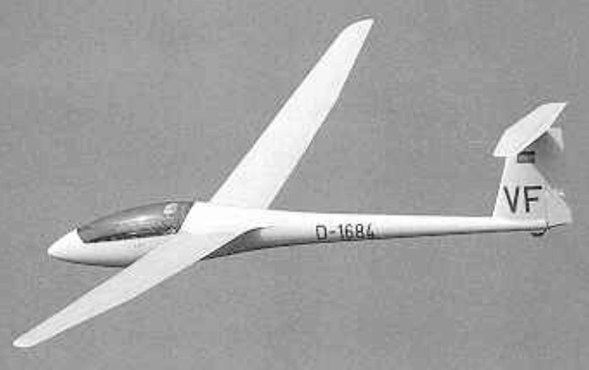
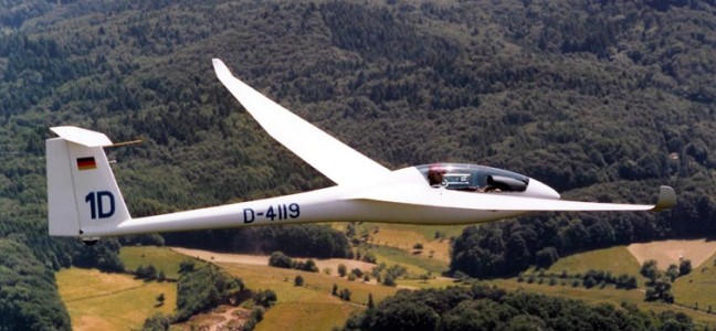
The glider has the characteristically double tapered wing with Wortmann profile and kink in leading and trailing edge. Adding the 18-Meter-tips with the noticeably smaller winglets the pilot experiences yet another substantial improvement of flight performances. Thus the lift/drag ratio rises to 48 and minimum sink improves to 0,51 m/s. in addition, 190 liters of water can maximally be carried in the 4 wing tanks, such requires center of gravity correction with water in the fin tank. All control connections are made automatically; double flange airbrakes are installed in the upper carbon fiber sandwich surfaceThe engine installation of the LS8-st with a Solo 2350 weighs complete with Fuel approx. 50 kg, made up for by the all up weight increase to 575 kg.

The original pneumatic retraction mechanism proved expensive and unreliable; DG replaced it with the proven linear bearing actuator for their production version. Operation of the 15 KW engine kept deliberately simple with the DG proprietary control unit. Travel distance with sustainer is approx. 300 km.

After the acquisition of Rolladen Schneider by DG-Flugzeugbau in July 2003 production of the LS8 continued very successfully despite initial legal problems. The finish of the airplanes manufactured at DG is reportedly noticeably better. The LS8 will be available again as an “LS8-s” (and not as “DG-700” or similar). We will continue the 15m version as well as the 15/18m version and the Turbo with the newly developed engine actuation. Delivery is possible from summer 2004.

Variants:

LS8-a
Top performance with 15 m wing span

LS8-s
High Performance Sailplane with 15 or 18 m of wing span
By adding the 18 meter tips the Standard Class Glider LS8 becomes the LS8-s. Despite the bigger wing span the outstanding flying characteristics of the LS8-a stay the same but now with performance numbers which are comparable to the open class of the seventies.
Although there are no wing flaps the LS8-s has reached best possible results in 18 meter class competitions under weak but also at best possible weather conditions. Obviously the wing section (a derivative of the LS6, as it is well known) is still a match to the most actual airfoil designs. The combination of very easy handling qualities, of having no problems when encountering turbulent conditions, minimum performance loss because of dirty or wet wings means a well proven competition glider which is also suitable for club operations or flying just for the joy of it.
For the LS8-s an increase of the maximum take-off weight from 525 to 575 kg could be done for the 18m version in combination with the shock-absorbing retractable 5″main wheel.

LS8-t
High Performance Sailplane with 15 or 18 meters of wing span and self-sustainer
As the popularity of the LS8-s began to increase more and more the question about a self-sustainer version was heard. Being able to get home on a weak day and travel by glider beyond the weather borders becomes reality with a self-sustainer engine. Furthermore the LS8-s with the increased wing span carries the additional weight of the engine installation better than a pure 15m sailplane. So we made the LS8-st with a self-sustainer, the LS8-s “turbo”.
The mold lines of the LS8-s were not changed – it was not even required to enlarge the fuselage.
The engine is the Solo 2350 two stroke two cylinder motor which is already well proven as a propulsion for sailplanes. The rigid two blade propeller is produced by Technoflug. With an additional weight of about 40 kg for the engine installation plus 10 kg of fuel there results a climb performance of 1 to 1.5 m/s and a range of 300 km or an endurance of 1 hour
The propulsion system was purposefully made as simple as possible. The engine plus propeller is very easy to install / uninstall.
If a customer should like to install the engine later, he can purchase a only motor-prepared version, too.

At the 1995 World Championships at Omarama, New Zealand, LS-8’s scored 2nd, 4th and 5th in the Standard Class.

LS8 Standard Equipment –
automatic control system connectors
retractable and sprung undercarriage
C.G. hook, retractable with landing gear
Nose tow hook
adjustable rudder pedals
wheel brake
Piggott-Hook
canopy with instruments panel hinged up front
infinitely adjustable trim system
oxygen flask receptacle
radio antenna in vertical tail fin
standard instrument panel
side pocket
double tapered wing in Carbon-sandwich-construction
15m winglets in Carbon-construction
ready to use water ballast system with funnel
ailerons in Carbon-construction
upper surface, double height air brakes
horizontal tail plane in Carbon-sandwich-construction
elevator in Carbon-Kevlar-construction
all control surface gaps sealed
backrest including headrest
temporary hinge at canopy rear for clean separation during emergency jettison
total energy connection in vertical fin
safety harness (multiple point buckle type)
registration signs
Cotton canopy cover
Optional Equipment
Tail dolly, covers for wings, leather upholstery, every instrument system offered, tail wheel 210x65mm, contest numbers, etc.

LS8 15m / 18m
Fuselage Length 6,72 m
Fuselage Width 0,61 m
Fuselage height 0,80 m
Wing Span 15,0 m / 18,0 m
Wing Area 10,5 m 11,4 m
Aspect Ratio 21,4 / 28,4
Min. Wing Loading about 32 kg/sq.m / ca. 30 kg/sq.m
Max. Wing Loading 50 kg/sq.m / 46 kg /sq.m
LS8-s /st: 50 kg/sq.m
Empty weight approx. 265 kg / 270 kg
Max. Take-off Weight 525 kg
LS8-s / st: 575 kg
Max. Cockpit Load 110 kg
Best Glide Ratio approx. 43 / 48
Minimum Sink Rate approx. 0,59 m/s / 0,51 m/s
Seats 1

LS8-st
Engine Solo 2350 ca. 18 hp
Fuel capacity 13 l
Climb rate in powered flight 1 -1,5 m/s

Rolladen-Schneider LS 7

Designed Wolf Lemke, this Standard Class sailplane first flew in 1987, and uses a modified LS-6 fuselage. It is fitted with a tail ballast tank for trimming purpose.

Span: 15 m / 49.2 ft
Area: 9.74 sq.m / 104.84 sq.ft
Aspect ratio: 23
Empty Weight: 235 kg / 520 lb
Payload: 251 kg / 553 lb
Gross Weight: 541 kg / 553 lb
Wing Loading: 55.54 kg/sq.m / 11.35 lb/sq.ft
Water Ballast: 0
L/DMax: 43
Seats: 1

Rolladen-Schneider LS 6

Designed by Wolf Lemke, the 15 m racing class LS-6 first flew in 1983. The flaps are linked to the ailerons. Approach control is by top surface Schempp-Hirth airbrakes. Forty were built.

The type became popular with competition pilots — the first two places being won in the 1985 World Glid¬ing Championships at Rieti, Italy; the first three places in the 1987 Worlds in Benalla, Australia; and the first four places (using later B and C models) at Uvalde in Texas in 1991.

The LS-6a and -6b models had an optional 5 kg / 12 lb fin ballast tank.

At the 1991 World Championships at Uvalde, TX, the first four places were taken by LS-6b’s and LS-6c’s.

The LS-6 comes with tip extensions increasing the span to 17.5 m. (LS- 6c/ 17.5) and 18.0 m. (LS-6c/18.0 m.)

Structure: composite/ CFRP mainspar/ Kevlar

Span: 15 m / 49.2 ft
Area: 10.5 sq.m / 113 sq.ft
Aspect ratio: 21.4
Airfoil: Wortmann mod.
Empty Weight: 250 kg / 551 lb
Payload: 275 kg / 606 lb
Gross Weight: 525 kg / 1157 lb
Wing Load: 50 kg/sq.m / 10.25 lb/sq.ft
Water Ballast: 180 kg / 397 lb
L/DMax: 40
Seats: 1

Rolladen-Schneider LS 4

LS4-B

Design work on this Standard Class sailplane began by Wolf Lemke in the winter of 1978 as the successor to the LS-1. The LS4 has a modified LS3-a GFRP/foam sandwich fuselage married to a new thin-section Wortmann mod. wing mounted in the mid position, and with a double taper planform, and a variety of rigging improvements. It has larger upper-surface double segment Schempp-Hirth type air brakes in the upper surfaces, but flaps are not fitted. The cantilever T-tail has separate elevators rather than an all-moving tailplane,and the retractable monowheel has rubber suspension and a cable-operated brake. There is a rubber bumper type tailskid with a semi-recessed tailwheel offered as an alternative. The pilot sits under a canopy that hinges upward and forward to open, and up to 140 litres of water ballast can be carried. The same glassfibre/foam sandwich construction as the LS3’s is employed.

The prototype LS- 4, registered D-6680, first flew 28 March 1980. Production began in the autumn of that year and by the spring of 1981 50 LS4s had been built out of 160 on order.

The type took the first seven places in the Standard Class at the 1981 World (Gliding Championships at Paderborn, West Germany.

The improved LS-4a has an increased gross weight and ballast capacity and strengtened landing gear. LS-4s took the first 6 places (and 21 out of the first 25) in the Standard Class at the 1983 World Championships at Hobbs, NM.

Over 600 were built.

Span: 49 ft 2.5 in
Length: 22 ft 1 in
Area: 10.5 sq.m / 113 sq.ft
Aspect ratio: 21.4
Airfoil: Wortmann mod
Empty Weight: 238 kg / 525 lb
Payload: 234 kg / 515 lb
Gross Weight: 472 kg / 1040 lb
Wing Load: 44.9 kg/sq.m / 9.21 lb/sq.ft
Water Ballast: 140 kg / 308 lb
L/DMax: 40.2 102 kph / 55 kt / 63 mph
MinSink: 0.60 m/s / 1.97 fps / 1.17 kt at 51.5 mph
Seats: 1

Rolladen-Schneider

Walter Schneider and Wolf Lemke commenced glider production in 1968 with the LS1 in the standard class; with the LS3 in 1977 the entrance into the racing class followed.

In 1980 evolved in co-operation of Lemke and Hans Jörg Streifeneder in the LS4 as a successor of the LS1.

1984 the racing class glider LS6, which replaced the LS3, was introduced.

By adding winglets and removing flaps 10 Years later the LS8 developed and first places at the European Championships 1994 and the World Championships 1995 soon proved the successful concept of the LS8.

In 2003 Rolladen-Schneider Flugzeugbau GmbH was taken over by DG Flugzeugbau GmbH (formerly Glaser-Dirks). Rolladen-Schneider had gone into receivership, and DG Flugzeugbau did not take over the liabilities but only the rights to build the gliders and use the brand name.

Rockwell- MBB X-31

The X 31 began as an Enhanced Fighter Manoeuvrability (EFM) demonstrator at NASA’s Dryden Flight Research Center at Edwards AFB. Designed to break the “stall barrier,” allowing it to flight at angles of attack which would typically cause an aircraft to stall with a complete loss of control, the X-31 employs thrust vectoring paddles that are located in the jet exhaust and small computer-controlled canards to help keep the aircraft stable at high attack angles. It incorporates an unusual delta wing design and three thrust vectoring paddles made of graphite epoxy and located on the aircraft’s aft fuselage. These direct the engine exhaust to provide control in pitch (up and down) and yaw (right and left) thereby increasing the aircraft’s manoeuvrability. In addition, the X 31 is configured with movable forward canards, wing control surfaces and fixed aft strakes. Coupled with advanced flight control systems, the result confers a significant advantage over conventional fighters in a close in combat situation.

The X 31 is the first co operative international X plane. At Dryden, the International Test Organization (ITO) expanded the flight test envelope. The ITO, managed by the Advanced Research Project Agency (ARPA), includes NASA, the US Navy, the US Air Force, Rockwell Aerospace, the Federal Republic of Germany and Deutsche Aerospace, formerly Messerschmitt Bolkow-Blohm.

To reduce costs, several parts of existing aircraft were used in the X 31. Canopy, ejection seat and control stick were taken from an F/A 18 while several parts of the landing gear and rudder are from an F 16. Brakes and wheels were provided by Cessna and are the same as those used on the Cessna Citation. Piloted by Rockwell chief test pilot Ken Dyson, the first aircraft, serial 164584, flew from Air Force Plant 42, Palmdale, Calif, on October 11, 1990. The second aircraft, 164585, made its first flight on January 19, 1991, with Deutsche Aerospace chief test pilot Dietrich Seeck at the controls. Powered by a single General Electric P404 GE 400 turbofan engine, known to be tolerant in disturbed air and capable to produce 16,000 lb of thrust with afterburner, the maximum speed achieved by the X 31 is Mach 1.28. Controlled flight at 70o angle of attack was accomplished at Dryden on November 6, 1992. On April 29, 1993, the X 31 successfully executed a rapid minimum radius, 180o turn using a post stall manoeuvre, flying well beyond the aerodynamic limits of any conventional aircraft. Later that summer, the first simulated dog-fights were performed against a NASA F/A-18 Hornet. This resulted in 63 victories for the X-31.

The first X-31 was lost in an accident on January 19, 1995, on its 292nd flight. Due to miscommunication between pilot and air traffic control and a missing pitot tube heating system the German pilot, Karl Heinz Lang, had to eject from his uncontrollable aircraft at 18,000ft. The aircraft crashed near Edwards AFB.

The second X-31 completed the 580th and last flight of its original research program on 13 May 1995 and was placed in storage.

In February 1998, the participating contractors started VECTOR Risk Reduction and Requirements Definition. The aircraft was shipped to NAS Patuxent River in April 2000, where it was largely rebuilt for the Vector (Vectoring Extremely Short Take-Off and Landing Control Tailless Operation Research) program.

VECTOR stands for Vectoring Extremely Short Take-Off and Landing Control and Tailless Operational Research and is being used to research extremely short take off and landing capabilities and also the aerodynamic characteristics of tailless flight using integrated thrust vector control. Three technology areas are involved:
Extremely Short Take Off and Landing (ESTOL) using thrust vectoring control

  • Flush Air Data System (FADS)
  • Tailless/reduced vertical tail configurations

This incorporated a new flight control software system was installed together with an auto throttle system, a belly mounted video camera and components of inertial navigation and global positioning systems. The revised aircraft made its first flight for Vector on 24 February 2001. After two months of basic flight testing, the aircraft began a year of upgrading and ground testing to perform ESTOL landings to a “virtual runway” at 5,000 feet. The X-31 took to the air again on 17 May 2002.

In these flights the aircraft flew thrust vectored, high precision ESTOL landings at reduced speeds and at high angles of attack.

To perform the automated approach, the pilot must fly into an invisible engagement box in the sky, then activate the ESTOL mode. Once successfully engaged, the pilot is not in control but is able to override the approach at any point. A video camera under the belly of the aircraft will allow the pilot to view the runway prior to landing because a pilot loses sight at anything above 15 degree angle of attack, so during final approach the aircraft will be controlled by autopilot. Coming in with its nose pointed high above the horizon, the first part of the aircraft to touch the runway would be the engine nozzle and not the landing gear. To prevent such an event, the X 31 performs [an automatic] derotation manoeuvre when the tail is just two feet above the runway, dropping onto its main landing gear. Timing of this manoeuvre is crucial; if the aircraft derotates early and drops too far, the landing gear could fail; if the aircraft derotates too late or too low, the tail could strike the runway. The aircraft is guided during approach by an Integrity Beacon Landing System (IBLS) which uses differential GPS data together with ground-based beacons to determine the aircraft’s position ensuring accurate positioning within two centimetres.

After 51 flights, the X 31 completed its first test phase on March 22, 2003, with two supersonic flights focussing on FADS performance. Pilot Knoptel reached speeds of Mach 1.06 and 1.18, in full afterburner at 39,000ft. While supersonic, he induced combinations of angle of attack and sideslip to tax the FADS. By night, engineers had processed the data and were able to confirm that the FADS was performing as desired throughout the flight regime.

This cleared the way for the final phase of flight tests that began in early April 2003 and ended on April 29 when the last ESTOL landing was performed by Maj Allee following a week of successful testing the world’s first fully automated, thrust vectoring landings. This landing was performed with an angle of attack of 24 o and a speed of 121kt, a reduction of 31% compared with the normal landing speed of 175kt. The X 31 requires a normal runway length of 8,000ft to stop after a conventional landing, but after the final ESTOL landing, the aircraft needed just 1,700ft to slow down enough to turn around on the runway.

Sponsors: DARPA, USN, German MoD
Fastest Flight: Mach 1.28 (900 mph)
Highest Flight: 40,000 feet (approx)

X 31
Powerplant: One General Electric P404¬GE 400 turbofan, 16,0001b thrust with afterburner
Span; 23,83ft (7.3m)
Length, 43.33ft (12.8m)
Take off weight, 16,1001b (7,303kg)
Max achieved speed, Mach 1,28 at 35,000ft
Max achieved altitude, 40,000ft (12,200m)

X-31A
Powerplant: one 10,600-lb (4808-kg) thrust General Electric F404-GE-400 non-afterburning turbofan
Wingspan 23 ft 10 in (7.26 m)
Length 43 ft 4 in (13.21 m) excluding probe
Height 14 ft 7 in (4.44 m)
Wing area 226.3 sq ft (21.02 sq.m)
Canard foreplane area 23.6 sq ft (2.19 sq.m)
Maximum speed 597 mph (961 km/h) or Mach 0.9 at 35,000 ft (10,670 m)
Empty weight 10,212 lb (4632 kg)
Maximum take-off 13,968 lb (6335 kg)
Crew: 1

Rockwell

Rockwell-Standard Corp
North American Rockwell Corp
Rockwell International Corp

In 1919, Colonel W.R. Rockwell reorganised a bankrupt axle company in Oshkosh, Wisconsin. Following the Colonel’s development of the first double reduction axles for heavy-duty vehicles, Timken-Detroit Axle company acquired his axle company in 1928.

In 1953, Timken-Detroit merged with Standard Steel Spring Company to form Rockwell Spring and Axle Company. In 1958, the name of the company was changed to Rockwell-Standard Corporation. Rockwell-Standard embarked on a plan of diversification in the late 1950s and 60s and by 1967, it was a major independent producer of a wide-range of automotive components.

In 1965 Rockwell-Standard acquired Snow Aeronautical, continuing to produce agricultural aircraft at Olney as Snow Commanders (as division of Aero Commander), and acquired Intermountain Manufacturing Company (IMCO) 1966. Single-engined Model 112 delivered to customers from 1972. Low-wing twin-engined Rockwell Commander 700 produced jointly with Fuji in Japan. Thrush Commander was very notable specially-designed agricultural aircraft. The entire Thrush Commander range sold to Ayres Corp and then became known by the Ayres name. Shrike Commander 500S terminated 1980 but Commander Jetprops continued by Gulfstream American Corporation.

In 1967, Rockwell-Standard Corporation and North American Aviation merged to create the North American Rockwell Corporation.

Following company reorganization, the former Aero Commander division of Rockwell became part of NAR, and its Shrike, Commander 685 and Turbo Hawk Commander twin-engined business aircraft were marketed under the new company name, together with Quail, Sparrow, Snipe and Thrush Commander agricultural aircraft, and the Darter and Lark Commander single-engined lightplanes.

The Model 112 Commander lightplane and B-1 swing-wing supersonic bomber projects were started before the company name was changed to Rockwell International in 1973.

In 1973 North American Rockwell and Rockwell Manufacturing Company merged to become Rockwell International Corporation. Aircraft production after the 1967 merger included the Aero Commander line of single and twin-engine aircraft, the turboprop OV-10 Bronco armed reconnaissance aircraft, T-2 Buckeye jet trainer, B-1B Lancer supersonic swing-wing bomber, and the Sabreliner executive and light jet transport. Company’s aerospace and defence units purchased by the Boeing Company on December 6,1996, becoming Boeing North American. Similarly, Rockwell Australia became Boeing Australia Ltd.

In 1977 Rockwell International sold its agricultural airplane operation to the Ayres Corporation of Albany, Georgia. The new owners will continue to manufacture the Models 600 and 800 Thrush Commanders. Fred Ayres, who developed the Turbo Thrush PT6 retrofit, plans to begin producing that airplane at his new plant.

1984: Sabreliner Corporation, a new company formed to acquire the former Sabreliner Division of Rockwell International.