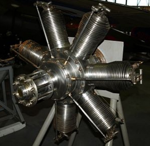
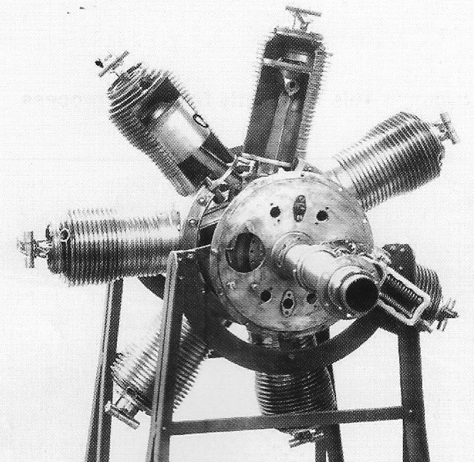
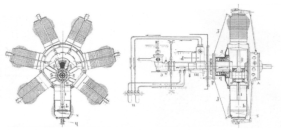
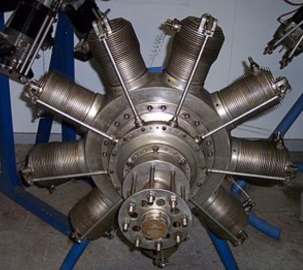
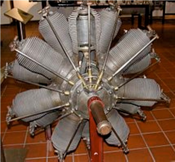
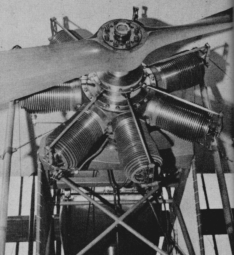
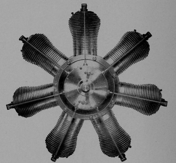
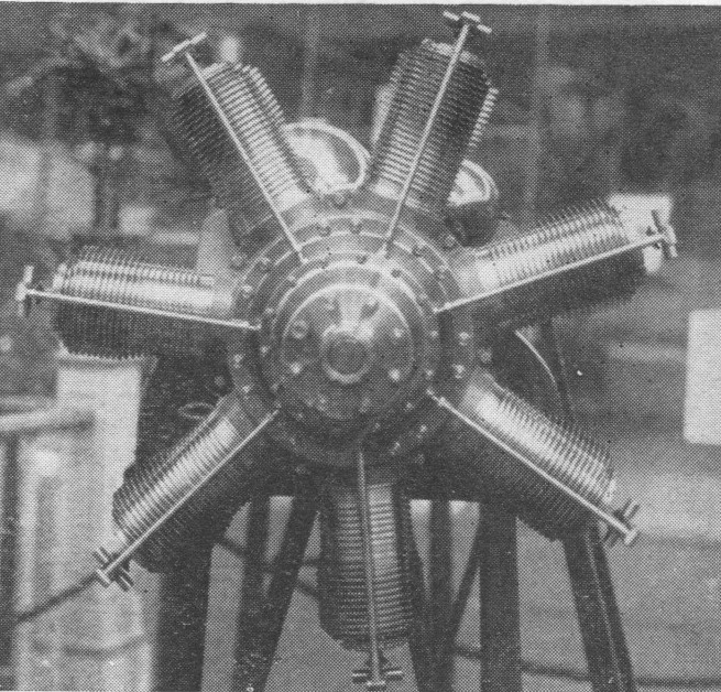
The Gnome 7 Omega (commonly called the Gnome 50 hp) is a French seven-cylinder, air-cooled aero engine. It was shown at the Paris Aero Salon held in December 1908 and was first flown in 1909. The unit cost in 1909 was £520.
It was the world’s first rotary engine produced in quantity, and its introduction revolutionized the aviation industry and it was used by many early aircraft. 4,000 had been produced until 1914 (more later). It produced 50 horsepower (37 kW) from its capacity of 8 litres (488 cubic inches).
Gnome 50 hp
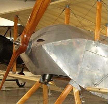
A Gnome Omega engine powers the 1912 Blackburn Monoplane, owned and operated by the Shuttleworth Collection, the oldest known airworthy British-designed aeroplane worldwide.
A two-row version of the same engine was also produced, known as the Gnome 14 Omega-Omega or Gnome 100 hp. The prototype Omega engine still exists, and is on display at the United States’ National Air and Space Museum.
Variants Gnome 7 Omega Single-row 7-cyl. original version; 50 hp (37 kW). Gnome 14 Omega-Omega Two-row, 14-cylinder version using Omega cylinders; 100 hp (75 kW).
Applications:
Gnome 7 Omega
Avro Type 500 Blackburn Mercury Blackburn Monoplane Blériot XI Bristol Boxkite Bristol Racing Biplane Bristol Monoplane Bristol-Prier P.1 Bristol-Coanda School Monoplane Bristol-Coanda T.B.8 Burga Monoplane Fabre Hydravion Henry Farman Type Militaire Grahame-White School Biplane Koolhoven Heidevogel Nieuport Monoplane Paulhan Biplane Pemberton-Billing P.B.9 Royal Aircraft Factory B.E.3 Royal Aircraft Factory B.E.4 Royal Aircraft Factory F.E.2 Short S.27 Short Tandem Twin Short S.37 Tractor Monoplane Short Triple Twin Short S.47 Triple Tractor Short S.62 Sopwith Bee Sopwith Sparrow Valkyrie Type B Vickers No.6 Monoplane Vickers No.7 Monoplane Vickers Boxkite School Biplane
Gnome 14 Omega-Omega
Bristol Gordon England G.E.2 Coventry Ordnance Works Biplane 10 Nieuport Monoplane Short S.41 Tractor Biplane Short S.57 Seaplane Short S.64 Folder Seaplane Short S.74 Admiralty Seaplane
Specifications:
7 Omega Type: 7-cylinder, single-row, rotary engine Bore: 110 mm (4.3 in) Stroke: 120 mm (4.7 in) Displacement: 8 L (488.5 cu in) Length: 79 cm (31 in) Diameter: 84 cm (33 in) Dry weight: 75 kg (165 lb) Valvetrain: pressure-driven inlet valves were located on the pistons Oil system: Total loss, castor oil Cooling system: Air-cooled Reduction gear: Direct drive, right-hand tractor, left-hand pusher Power output: 37 kW (50 hp) at 1,200 rpm
The Monosoupape (French for single-valve), was a rotary engine design first introduced in 1913 by Gnome Engine Company (since 1915 called Gnome et Rhône). It used an arrangement of internal transfer ports and a single pushrod-operated exhaust valve to replace a large number of moving parts found on more conventional rotary engines, and made the Monosoupape engines some of the most reliable of the era. British aircraft designer Thomas Sopwith described the Monosoupape as “one of the greatest single advances in aviation”.
Produced under license in Britain the engine was built in large numbers in both seven and nine-cylinder versions, the latter being produced with two different displacements.
Contrary to the Le Rhône designs, earlier Gnome engines like the Gnome Omega, Lambda and Delta used a unique arrangement of valves in order to avoid needing pushrods and other complex devices that operated during the inlet phase of the combustion cycle on more conventional engines. Instead, a single exhaust valve on the cylinder head was operated by a pushrod that opened the valve when the pressure dropped at the end of the power stroke. A pressure-operated inlet valve, which was balanced by a counterweight to equalize the centrifugal forces, was placed in the centre of the piston crown, where it opened to allow the fuel–air charge to enter from the engine’s central crankcase.
Although ingenious, the system had several drawbacks: the cylinder heads had to be removed both in order to perform maintenance of the intake valve, which could easily become jammed, and in order to adjust the timing and pressures correctly for the rod-less operation; and the Gnomes exhibited even poorer fuel economy than other rotaries because the inlet valves opened at times that were not efficient.
In 1913, Louis Seguin and his brother Laurent (engineers who founded the Société Des Moteurs Gnome [the Gnome motor company] in 1905) introduced the new Monosoupape series, which eliminated the inlet valve, replacing it with piston-controlled transfer ports similar to those found in a two-stroke engine. Beginning with the power stroke, the four-stroke engine operated normally until the piston was just about to reach the bottom of its stroke (bottom dead center, or BDC), when the exhaust valve was opened “early”. This let the still-hot burnt combustion gases “pop” out of the engine while the piston was still moving down, relieving exhaust pressure and preventing exhaust gases from entering the crankcase. After a small additional amount of travel, the piston uncovered 36 small ports around the base of the cylinder, leading to the crankcase which held additional fuel–air mixture (the charge). No transfer took place at this point since there was no pressure differential; the cylinder was still open to the air and thus at ambient pressure. The overhead valve exhausted directly into the slipstream since there was no exhaust manifold in order to save weight.
During the exhaust stroke, total scavenging occurred as the air moving past the cylinder exterior lowered the pressure inside due to the direct exposure of the exhaust port to the slipstream. The piston continued its exhaust stroke until top dead center (TDC) was reached, but the valve did not close. The piston began to move down on its intake stroke with the valve still open, pulling fresh (presumably un-filtered) air into the cylinder. It remained open until it was two-thirds of the way down, at which point the valve closed and the remainder of the intake stroke greatly reduced the air pressure. When the piston uncovered the transfer ports again, the low pressure in the cylinder drew in the balance of the charge.
The charge was an overly rich mixture of air, which was acquired through the hollow crankshaft, and fuel that was continuously injected by a fuel nozzle on the end of a fuel line, entering the crankcase through the hollow crankshaft. The nozzle was in the proximity of, and aimed at, the inside base of the cylinder where the transfer ports were located. The fuel nozzle was stationary with the crankshaft, and the cylinders rotated into position in turn. The compression stroke was conventional.
The spark plug was installed horizontally into the rear of the cylinder at the top but had no connecting high-voltage wire. An internal-tooth ring gear mounted on the engine drove a stationary magneto mounted on the firewall, whose high-voltage output terminal was in close proximity to the spark plug terminals as they passed by. This arrangement eliminated the need for points, distributor, high-voltage wiring and capacitors found in conventional mechanically timed ignition systems. This ring gear also drove the oil pump, which supplied oil to all bearings, and through hollow pushrods to the rockers and valves and also drove an air pump which pressurized the fuel tank. The later Gnome 9N engines had dual ignition systems for safety, with twin spark plugs per cylinder which were electrically wired, with the wires routed onto the crankcase and a central pair of magnetos driven by the spinning engine crankcase.
The Monosoupape had no carburetor or throttle, and since most of its air supply was taken in through the exhaust valve, it could not be controlled by adjusting the air supply to the crankcase like other rotaries. Monosoupapes therefore had a single petrol regulating control used for a limited degree of speed regulation. In early examples, engine speed could be controlled by varying the opening time and extent of the exhaust valves using levers acting on the valve tappet rollers, but this was later abandoned due to causing burning of the valves. Instead, a blip switch was used, which cut out the ignition when pressed. This was used sparingly to avoid damaging the engine, since it was only safe to be used when the fuel supply was also cut. Some later Monosoupapes were fitted with a selector switch which allowed the pilot to cut out three or six cylinders instead of all nine when hitting the blip switch, so that each cylinder fired only once per three engine revolutions but the engine remained in perfect balance.
The lubrication system, as with all rotary engines, was a total-loss type in which castor oil was injected into the fuel–air mix with a small pump. Castor oil was used because it could not be easily dissolved into the fuel, and because it possessed lubrication qualities superior to mineral oils of the day. Over two gallons of castor oil were sprayed into the air during each hour of engine operation. This explains why most rotaries were fitted with a roughly 270º perimeter “horseshoe”-shape ring cowl, with the lowermost quarter of the cowl omitted to be open at the bottom. The cowl directed the spray of castor oil, along with sparks from the exhaust, away from the flammable aircraft structure. Unburnt castor oil from the engine tended to be hurled into the pilot’s face, often having a laxative effect on the pilot if ingested.
Because the entire engine rotated, it had to be precisely balanced, requiring precision machining of all parts. As a result, Monosoupapes were extremely expensive to build, the 100 horsepower (75 kW) models costing $4,000 in 1916. However, they weighed slightly less than the earlier two-valve engines and also used less lubricating oil.
Variants:
Gnome Monosoupape 7 Type A (1916) Seven-cylinder rotary engine, 80 hp (60 kW). Bore and stroke: 110 x 150 mm (4.3 x 5.9 in). Gnome Monosoupape 9 Type B-2 (1916) Nine-cylinder rotary engine, 100 hp (75 kW). Bore and stroke: 110 x 150 mm (4.3 x 5.9 in). 2,188 units produced under license in Britain. Gnome Monosoupape 9 Type N (1917) Nine-cylinder rotary engine, larger diameter crankcase than the B-2, 150 or 160 hp (112 or 119 kW). Bore and stroke: 115 x 170 mm (4.5 x 6.7 in).
The Gnome-Rhône 7K Titan Major was a seven-cylinder 370 hp (270 kW) air-cooled radial engine, that started life as an enlarged Gnome-Rhône 5K with two extra cylinders. The Gnome-Rhône 5K was itself a licensed version of the Bristol Titan. The 7K is very comparable to the Bristol Neptune seven-cylinder engine since they used the same technology. The 7K was followed by the larger and more powerful nine-cylinder 550 hp (405 kW) Gnome-Rhône 9K Mistral. Gnome-Rhône later responded to the need for a more powerful engine by developing the 7K into a two-row version that became the Gnome-Rhône14K Mistral Major.
The CNIAR IAR 7K was a licence-built Gnome-Rhône 7Ksd, 420 hp aircooled 7-cyl radial.
Applications: Bernard 160 Breda Ba.25 Breguet 393T Breguet 414 FBA 291 FBA 294 Lioré et Olivier LeO H-199 Lioré et Olivier LeO 203 Lioré et Olivier LeO H-242 Morane-Saulnier MS.235 Potez 33/3 Rogožarski PVT Rogožarski R-100 SET 7 SPCA 80 SPCA 90 Wibault 280 Wibault 362
The Gnome 7 Lambda was a French designed, seven-cylinder, air-cooled rotary aero engine that was produced under license in Britain and Germany. Powering several World War I era aircraft types it was claimed to produce 80 horsepower (60 kW) from its capacity of 12 litres (720 cubic inches) although recorded figures are lower.
Gnome 7 Lambda
Just under 1,000 units were produced in Britain, the majority (967) by the Daimler Company of Coventry. A 14-cylinder variant was known as the Gnome 14 Lambda-Lambda.
In Germany Motorenfabrik Oberursel license-built the seven-cylinder engine as the Oberursel U.0 and later copied the 14-cylinder design and designated it as the Oberursel U.III.
Gnome 7 Lambda
Variants: Gnome 7 Lambda Seven-cylinder, single-row rotary engine. Gnome 7 Lambda (long stroke) Increased stroke of 145 mm (5.7 in) to raise the compression ratio to 3.87:1, and total displacement to 12.26 litres. Gnome 14 Lambda-Lambda 14-cylinder, two-row rotary engine using Lambda cylinders. 160 hp (120 kW). Motorenfabrik Oberursel U.0 German production of the Gnome 7 Lambda – had a 124mm cylinder bore and 140mm piston stroke for a total displacement of 11.52 litres, external diameter of 1.020 meters.
Applications:
Gnome 7 Lambda Avro 504 Blackburn Type I Blériot Parasol Blériot XI Bristol Boxkite Bristol Gordon England G.E.3 Bristol-Coanda Monoplanes Bristol Coanda T.B.8 Bristol Coanda P.B.8 Bristol Scout Caudron G.III Deperdussin Type B Dunne D.8 Henry Farman F.20 Grahame-White G.W.15 L & P 4 Lowe Marlburian Nieuport IVG Nieuport 10 Radley-England Waterplane Royal Aircraft Factory B.E.3 Royal Aircraft Factory B.E.4 Royal Aircraft Factory B.E.8 Royal Aircraft Factory B.S.1 Royal Aircraft Factory S.E.2 Royal Aircraft Factory S.E.2 Royal Aircraft Factory S.E.4 Short S.37 Short S.38 Short S.41 Short S.60 Short S.70 Sopwith Gordon Bennett Racer Sopwith Pup Sopwith Sociable Sopwith Tabloid Sopwith Three-Seater Vickers No.8 Monoplane
Gnome 14 Lambda-Lambda Avro 510 Royal Aircraft Factory S.E.4 Deperdussin Monocoque Short S.63 Short S.64 Short S.70 Short S.74 Short S.80 Short S.81 Short S.82
Specifications:
Gnome 7 Lambda Type: 7-cylinder, single-row, rotary engine Bore: 124 mm (4.9 in) Stroke: 140 mm (5.5 in) Displacement: 11.8 L (721.2 cu in) Length: 112 cm (44 in) Diameter: 93 cm (36.6 in) Dry weight: 96 kg (212 lb) Valvetrain: Automatic centre-piston inlet valve, overhead exhaust valve (one each per cylinder) Cooling system: Air-cooled Reduction gear: Direct drive, right-hand tractor, left-hand pusher Power output: 50.3 kW (67.5 hp) at 1,250 rpm (maximum power) Compression ratio: 3.75:1
The Gnome 7 Gamma was a French designed, seven-cylinder, air-cooled rotary aero engine. Powering several pre-World War I era aircraft types it produced 70 horsepower (52 kW) from its capacity of 12 litres (680 cubic inches).
March 1909
A 14-cylinder variant was known as the Gnome 14 Gamma-Gamma.
Gnome 14 Gamma-Gamma 14-cylinder, two-row rotary engine using Gamma cylinders. 140 hp (104 kW).
Applications:
Gnome 7 Gamma Blériot XXI Bristol Biplane Type T Bristol Prier-Dickson Henry Farman Biplane Grahame-White Passenger Biplane VIIc Handley Page H.P.3 Morane-Borel seaplane Nieuport Monoplane Paulhan Biplane Royal Aircraft Factory B.E.3 Royal Aircraft Factory B.E.4 Short School Biplane Short S.32 Short S.36 Short S.38 Short S.45 Sopwith Three-Seater Vickers No.6 Monoplane Vickers No.8 Monoplane
Gnome 14 Gamma-Gamma Royal Aircraft Factory B.E.7 Short S.41
Specifications: Gnome 7 Gamma Type: 7-cylinder, single-row, rotary engine Bore: 120 mm (4.7 in) Stroke: 130 mm (5.1 in) Displacement: 11.14 L (679.84 cu in) Length: 112.7 cm (44.4 in) Diameter: 86.9 cm (34.2 in) Valvetrain: Automatic centre-piston inlet valve, overhead exhaust valve (one each per cylinder) Cooling system: Air-cooled Reduction gear: Direct drive, right-hand tractor, left-hand pusher Power output: 52.2 kW (70 hp) at 1,200 rpm
Cycle: 4 stroke No cylinders: Vee 2 Bore: 97 mm Stroke: 76 mm Compression: 8.5 Displacement: 1122 cc Cooling: air / oil Ignition: electronic Reduction: Poly-V belt 2.3/1 Weight: 57 kg Max pwr: 70 hp at 5800 rpm Max torque: 131 Nm at 4200 rpm Price 1998: 89 000 000 L
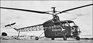
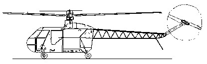
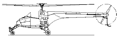
Work on the BŻ-4 Żuk began at the research institute Główny Instytut Lotnictwa – Main Aviation Institute in Warsaw in 1953, under the leadership of Dipl. Ing. Bronisław Żurakowski, who had earlier designed the experimental BŻ-1 GIL helicopter. Due to the delicate political situation in postwar Poland (Soviet influences and centrally planned economy), progress was slow. The main object was to produce a simple and inexpensive general use light helicopter. Its purpose was also to develop and test the novel rotor and transmission system, which eliminates vibration and improves control. Initially it was designated GIL-4. The BŻ-4 Żuk was based on a single main three-blade rotor powered by an indigenous one 320 hp Narkiewicz WN-4 piston engine in a fuselage made of a steel frame, behind a cabin section. It had an open frame rear boom structure and a fixed four-wheel undercarriage. Main rotor was atypical, for it had a smaller upper steering rotor and was fitted with an automatic stabilization system, of the Hiller principle. The cabin had four doors with two front seats and a rear bench. There were two fuel tanks, 220 litre in total. Four main variants were planned: a passenger version accommodating a pilot and three passengers, an ambulance variant carrying pilot, one stretchers and an attendant, an agricultural variant carrying pilot and spraying or dusting equipment and a dual control trainer. The first prototype of the BŻ-4 Żuk four-seat helicopter was manufactured and displayed publicly in the Polish Aviation Day Exhibition in August 1956. Due to a long program of ground testing and fixing faults, it flew first only on 10 February 1959 and completed 17 flights for a total of 3 hrs, 40 minutes. The Żuk was still in the development stage when further work was cancelled in favor of the licence production of the Mil Mi-1, that had already started in WSK PZL-Świdnik. The prototype was damaged during landing on 31 August 1959, and despite being repaired, it was not used again. Two additional prototypes were not completed. One damaged and incomplete prototype is preserved in the Polish Aviation Museum in Kraków.
Powerplant: 1× Narkiewicz WN-4 7-cylinder air cooled radial engine, 320 shp (237 kW) Fuselage length: 10.55 m Rotor diameter: 12 m (39 ft 4.5 in) Height: 2.8 m Empty weight: 1,050 kg (2,313 lb) Loaded weight: 1,500 kg (3,307 lb) Useful load: 450 kg Maximum speed: 156 km/h (97 mph) Range: 260 km (161 miles) Service ceiling: 3000 m Rate of climb: 4.6 m/s, 276 m/min Crew: one, pilot Capacity: three passengers
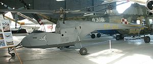
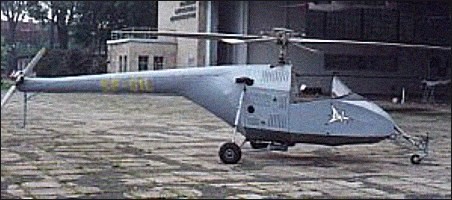
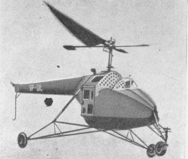
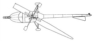
The BŻ-1 was designed at the research institute Główny Instytut Lotnictwa – Main Aviation Institute in Warsaw, from an initiative of Zbigniew Brzoska. The Polish aviation industry was destroyed after World War II, and in addition, the principal of the Institute was the only person who had seen a helicopter (Sikorsky R-4 in England). Despite severe material shortages, work on the experimental design started in 1948, and the main designer became Bronisław Żurakowski (brother of test pilot Janusz Żurakowski), who designed the helicopter rotor and the control system. It used simpler Hiller rotor type, with two auxiliary blades. The structure of the fuselage, tail boom, auxiliary rotor and tricycle undercarriage were designed by Tadeusz Chyliński. The power unit and final drive were designed by Zbigniew Brzoska. The design utilized some components left by the Germans, like a piston engine Hirth HM 504 (configured for vertical use) and wheels from a glider’s landing gear. Initially, the helicopter had no name. It only received the registration SP-GIL, from the Institute abbreviation, and soon it became known as GIL (gil also means bullfinch in Polish). Later it was also given the designation BŻ-1, from Żurakowski’s initials. The helicopter was completed by the end of 1949. During the first flight trial on 15 January 1950, it was overturned by a wind gust and had to be repaired. The test pilot was Bronisław Żurakowski, who taught himself fly a helicopter. The helicopter first flew on 4 April 1950, restrained on tethers by two men for a measure of safety. During 1950-1953, it underwent a test program and was often modified. At first it had elastic rotor blades. In 1950, it was fitted with rigid blades and an efficient simple custom designed resonant vibration eliminator. During tests, for different reasons, it crashed or was damaged without casualties, at least seven times and was repaired each time.
On 20 July 1952, the BŻ-1 GIL was first displayed to the public, during an air show at Okęcie airfield (it was one of first public helicopter presentations in the Eastern Bloc). On 16 November 1953 the helicopter was damaged when the main rotor was bent by the wind and cut off the rear pylon, thus ending the test program. By then, the prototype had completed 169 flights, 20 hours 21 minutes in total.
In 1956, the helicopter was repaired and used for training flights by helicopter pilots. On 28 June 1957, a tail rotor gear (originally from a World war II Zündapp motorcycle) broke and it could not be replaced, consequently, the helicopter never flew again, being written off in 1960. During 1956–1957 it had completed 185 flights, for a total of 12.5 hours. Currently, the sole BŻ-1 GIL prototype is preserved in the Polish Aviation Museum in Kraków.
Powerplant: 1× Hirth HM 504, 105 hp Length: 8.5 m Rotor diameter: 8.8 m / 28 ft. 11 in Rotors: 2-blade main; 2-blade tail Height: 2.29 m Disc area: 60.8 sq.m Empty weight: 380 kg Loaded weight: 610 kg / 1,276 lb Maximum speed: 140 km/h / 87 m.p.h Cruise speed: 120 kph Service ceiling: 2000 m Absolute ceiling: 3000m / 9,840 ft Range: 275km / 112 miles at 73 m.p.h. Rate of climb: 4.5 m/s Seats: 2
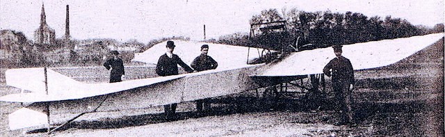
In May 1911, the Lwow press informed its readers about a successful flying demonstration of Glowinski’s monoplane. The machine, designed by Bronislaw Glowinski in 1910 and constructed and flown by him in Tarnopol, should therefore be regarded as the first Polish aeroplane to achieve a controlled and sustained flight in Poland.
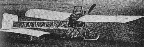
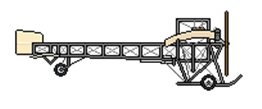
Construction: Giowiriski’s aircraft was a single-seat braced monoplane of composite construction. The wing, a two-spar wooden structure of double-surfaced type covered with fabric, was built in two sections. Each wing panel, carried immediately above the main fuselage frame on an inverted twin-V cabane, was attached to the base of the cabane and braced to its top by wires, and to a low cabane under the second fuselage frame and the landing-gear framework. To maintain lateral stability wing warping was employed. The fuselage, an open brass-welded metal-tube structure trussed by wires, was of rectangular section forward and triangular section aft, terminating in a vertical knife-edge at the tail. The landing-gear frame and all supporting cabanes were built of metal tubes integral with the fuselage. The pilot’s seat was situated at the rear of the rectangular fuselage section. The control system consisted of a conventional control stick and rudder bar, the controls being by cable, except for the elevator system which was by push-rod to the back of the rectangular fuselage section and thence by cable. The tail unit, a wooden structure covered with fabric, consisted of a rudder, a tailplane and Bleriot-type full-chord elevators, the tailplane being wire-braced to the fuselage top longerons and supported by a cabane under the rear end of the fuselage. The landing gear, of neat design, comprised two outwardly-splayed side Ns, supported by a pair of struts and coupled by two transverse tubes. A pair of long wooden skids was attached to this framework. A cross-axle, carrying two wheels, was attached by rubber shock-absorber cords to the skids. The tailwheel fork was provided with a spring shock-absorber. Power was supplied by the 25 hp Anzani three-cylinder air-cooled semi-radial engine directly driving a two-blade tractor airscrew. The fuel tank was attached to the wing-carrying cabane. The monoplane had a span of 10.2 m (33 ft 6 in).
The plane was built in 1910-11 in Tarnopol. Kostruktor Bronisław Głowiński modelled himself during the construction on the construction of the Bleriot XI “La Manche” aircraft.
The assembly of the aircraft was carried out in the constructor’s brother’s workshop, in a shed serving as a carpentry workshop and as a room for the final assembly of the aircraft.
Modelled to a certain extent on the lines of Bleriot Type No. XI, but embodying several original and imaginative features, the machine made a number of short flights over an improvised airfield near Tarnopol in the late spring and summer of 1911. Unfortunately, the designer was unable to obtain the required materials and was forced to use heavier substitutes. This increased the weight of the airframe beyond the anticipated figure, and a weary Anzani engine, overhauled and modified by Glowinski, did not provide the desired power and reliability. As a result the monoplane was rather underpowered and this, combined with frequent breakdowns on the part of the capricious powerplant, severely limited its capabilities and performance and prevented Glowinski from attempting any flights beyond the area of the improvised landing field. His ambition to undertake prize flights in Lwow was never realized.
The condition of the engine deteriorated quickly and some of the parts soon became worn beyond repair. The designer could not afford another engine, and, as the expected help from ZASPL never materialized, he dismantled his machine towards the end of 1911 and had to abandon flying altogether. Later, for a time, he attended the Lwow Technical University, and the forward section of his aircraft was displayed at the Second Aviation Exhibition in Lwow, which opened on 16 February, 1913. Unable to overcome financial difficulties and disenchanted with the unfulfilled promises of support from aviation organizations, he eventually left Poland before the 1914-18 War to work on the construction of railway lines in Asia, but came back after the end of hostilities. Parts of his monoplane, stored in various places, survived until the 1939-45 War.
Powerplant: 1 × Anzani 3-cylinder fan, 19 kW (25 hp) Wingspan: 10.20 m (33 ft 6 in) Wing area: 18.5 m2 (200 sq ft) Length: 8.00 m (26 ft 3 in) Height: 2.5 m (8 ft 2 in) Empty weight: 320 kg (700 lb) Gross weight: 400 kg (880 lb) Maximum speed: 60 km/h (40 mph, 35 kn) Range: 25 km (15 mi, 13 nmi) Crew: One pilot