Horton Ho VII

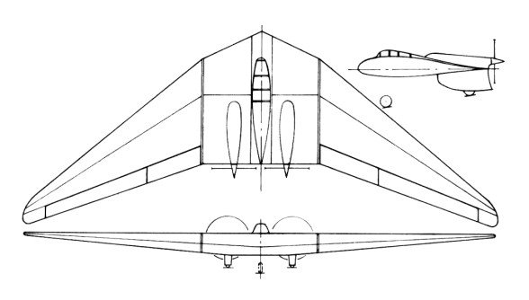
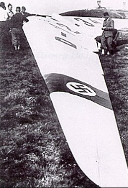
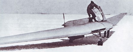
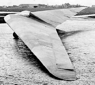
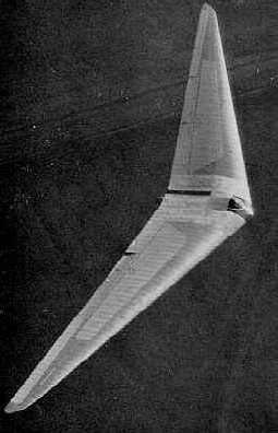
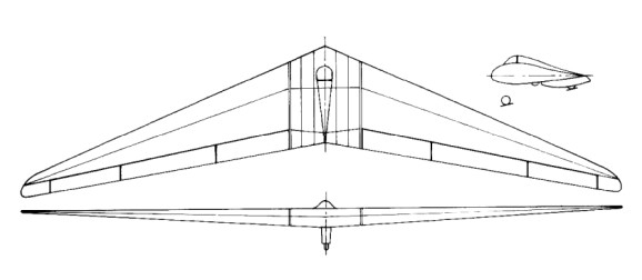
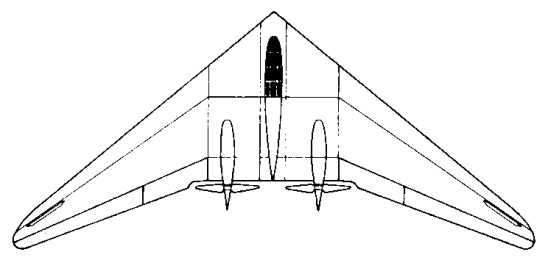
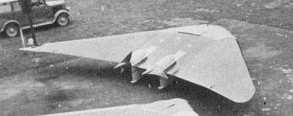
The H VII was projected in 1938 and the first of the type was built by Peschke at Minden in 1943. It bears a general resemblance to the modified H V in layout and control design and used the same outer wing panels: the span was the same (16m) the sweepback slightly greater (34 degrees) and aspect ratio 5.8 instead of 6.1. Its function seems to have been that of a high speed two-seater communications aeroplane and trainer for tailless pilots. Engines were Argus AS 10 C of 179kW / 240 hp.
Altogether two were completed and flown and a third was nearing completion at Minden when the district was occupied by the Allies. Two aircraft were damaged beyond repair and the third fell into Russian hands at Eilenburg.
Single stage elevon control was used on the H VII with 25% Frise nose and geared tab. Inboard of the elevons was a plain flap and in the middle trailing edge split flaps extending for the full width of the center section. Initially the graded flap angle principle was used, the part between the engines opening to 60 degrees, between the engine and the outer wing panels to 45 degrees, and the plain flap on the wing lowering to 20 degrees. When R.L.M. ordered the design in quantity however they asked for it to be simplified and for landing speed to be raised to give pilots more realistic training for high speed aircraft. The plain flap was accordingly locked up on the second aircraft and omitted altogether on the series production model.
Plug spoiler drag rudders of the H IV type were used on the first aircraft. These tended to suck open and had to be held closed by springs. They were not very satisfactory from the point of view of control forces and feel, and after about 10 flights they were scrapped and replaced by a new “trafficator” design. This was simply a bar which projected 40 cm in a spanwise direction from the wing tip when rudder was applied and retracted flush with the wing surface when not in use. Vent holes were cut to adjust aerodynamic balance. The vent holes allowed flow through the bar and deflected the flow sideways to generate a self-closing aerodynamic force. This was supplemented by a spring loading and the two components adjusted to give satisfactory feel on the rudder bar. This type of rudder was claimed to be cheap and easy to make and generally more satisfactory then previous designs.

The center section being of welded tube construction and the wings of single spar wooden construction with ply covering.
The undercarriage was a completely retractable four-wheel layout, the front wheel pair taking about 50% of the total weight when resting on level ground.
The constant speed airscrews were driven through extension shafts with a thrust ball bearing and rubber flexible coupling at the engine end and a self aligning ball bearing at the airscrew end mounted on a cantilever form the main structure.
Outer wing panels were of the same aerodynamic shape as those of the H V. At the center line the section was 16% thick with 1.8% camber (zero Cmo) graded to 8% symmetrical tip sections. Wing twist was 5 degrees; 2 degrees linearly and 3 degrees parabolically distributed. The aircraft trimmed with elevons neutral at 260 kph (CL = 0.16).

The following performance data were quoted by Reimar Horten from memory:
Flying weight (minimum) 2,900 kg
Flying weight with full equipment 3,200 kg
Engines 2 x 240 hp Argus AS 10 C (normally aspirated)
Sea level (crusing speed (180-200 hp per engine) 310 kph
Sea level (top speed) 340 kph
Normal take-off speed 110 kph
Ground run 250 meters
Sea level rate of climb at 180 kph (full power) 7 m/sec.
Ceiling 6,500 meters
CLmax = 1.2 no flaps
CLmax = 1.6 with all flaps
Delta CL due to plain flap was 0.1

Reimar Horten said that prior to the first flights at Scheidhauer on the H VII, his brother Walter had supervised the CG’ing of the aircraft and mistakenly put ballast in the nose because the measurements were made with a steel tape with 10 cm missing from the end. Scheidhauer’s commented that the aircraft had to be brought in at a minimum speed of 120 kph, with the stick nearly right back, if the nose was to be lifted for the hold off; the aircraft then floated (stick fully back) until 90 kph before touching down. Normal take-off procedure was to accelerate to 120 kph and then pull the stick back when the aircraft immediately took off and climbed away. Apparently it could be unstuck at 90 kph by pulling back hard but would not climb until 120 kph had been reached. It was impossible to stall the aircraft with the CG in this position; the general behavior was said to be “good natured”.
Walter flew the H VII (with the CG in its correct position) on 30-40 occasions, a total flying time of about 18 hours. (Scheidhauer’s time was also about 18 hours). Apparently the change in CG brought the approach speed down to about 100 kph and the aircraft could be touched down on the rear wheels. It was not certain that a complete stall could be produced in steady flight. With the stick fully back the aircraft sank on an even keel with fair lateral control. Lateral control was pleasant, the 25% Frise balance eliminated adverse yaw and virtually enabled flying on two controls.
Tests with the “trafficator” drag rudder showed that single engine flight could be maintained with half rudder and a little sideslip; turns could be made in level flight against the dead engine. On one test the pilot was carrying out a single engine approach when he realized that he had stopped the engine supplying the undercarriage hydraulics and could not lower the wheels. He was able to climb away, start the dead engine and made a normal landing.

Ho-VII
Engine: 2 x Argus As-10, 180kW
Max take-off weight: 2000 kg / 4409 lb
Empty weight: 1550 kg / 3417 lb
Wingspan: 16 m / 52 ft 6 in
Length: 7.5 m / 24 ft 7 in
Height: 2.5 m / 8 ft 2 in
Wing area: 44 sq.m / 473.61 sq ft
Max. Speed: 350 km/h / 217 mph
Crew: 2
Horton Ho V

The H V was designed form the outset as a powered aircraft using two Hirth H.M. 60 R motors driving oppositely rotating propellers through extension shafts. It has a span of 52.5 feet, aspect ratio of 6:1, and a quarter chord sweepback of 32 degrees. Engines were completely buried and drove propellers on extension shafts raised relative to the engine crankshaft and driven through a reduction gear. The undercarriage was of fixed tricycle type with castoring nose wheel and trousered main wheels. The nose wheel actually too 55% of the static weight when on level ground.
Three examples were built. The first, built at Ostheim in 1936 was constructed of plastic material with riveted sheet plastic covering. Pilot and passenger were contained entirely in the wing contour and the nose wheel was retractable. This aircraft crashed on its first flight, due mainly to its unorthodox waggle-tip control. The second version used more normal control methods and conventional construction, it was started in 1937 and flew successfully. In 1941 it was completely rebuilt as a single-seater, but retained the same control system.
In its original form the H V was fitted with waggle tip control in which the fore and aft sweep of the wing tips was geared to the stick, producing incidence change by a skew hinge arrangement. The aircraft crashed on it first flight due to the control taking charge after a bounce during landing. The reason for the accident was obscured by a failure of one engine but the control system was not regarded as satisfactory by the Hortens who later developed the idea further on an H III. They considered that damping is necessary to prevent the tips oscillating under suddenly applied acceleration (as occur during take off and landing).
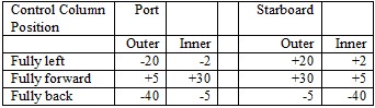
The second aircraft in both its forms had a two stage elevon control rather similar to the H III. Maximum control deflections were as follows:

The outer control flaps had a 20% Frise nose and assymmetrically geared tabe to compensate the non linear moment characteristics of the nose balance. The inner flap pair had round noses.
Split trailing edge flaps were fitted to the center section, the flap between the engines lowering to 60 degrees and the part outboard to 45 degrees. The inner elevon flaps dropped to 30° when the center section flaps were lowered and still operated as elevons about this new zero position. The idea of using graded flap deflections originated from a hunch of the Hortens that the sudden discontinuity and greater spanwise flow with ungraded flaps might cause stability and control troubles. They later found that this fear was unfounded and gave up the graded deflection principle.
Rudder control on the second two aircraft was by split nose flaps on the H III pattern.
A great deal of flying was done on the second and third H V’s, including about twenty flights on the latter in 1943 by Prof. Stuper of A.V.A. Gottingen. The Hortens themselves had lost interest in the H V because later designs incorporated many improvements. Stuper has also flown the H IIId with Walter Mikron engine.
Tests at A.V.A. were undertaken at the request of D.V.L. who wanted information on single engine characteristics and an unbiased comparison between tailless and conventional handling qualities. Stuper’s comments were as follows:
Longitudinal dynamic stability was good and no fundamental different from a conventional aircraft could be noticed. In rough air he thought it had a more abrupt pitch response than normal, which was only a disadvantage if gun platform steadiness was needed. (Walter Horten thought this effect might be due to the low wing loading (6 lb/sq.ft.) on the H V and Stuper agreed that this might be so).
Lateral stability appeared satisfactory. No tendency to “dutch roll” instability was found and no arratic changes of heading due to low Nv and Yv were noticeable. Stuper was in fact expecting trouble from this source but failed completely to find any. He added that his impressions were purely qualitative as they had no time to instrument the aircraft.
Controls were light and effective, with the exception of the rudder, which was heavy and not effective enough. Aileron was heavier than the elevator “in the ratio 4:3”. With the stick back, aileron movement was restricted, which Stuper thought a bad point since plenty of aileron was useful in an approach in gusty weather. The aircraft was in trim virtually over the whole speed range without movement of the elevator trimmer. When flaps were lowered there was a slight nose heavy tendency which could easily be held.
Summing up, Stuper said that aileron and elevator control were quite normal but rudder control needed improvement.
Behavior at the stall (flaps down) was very satisfactory, the nose dropped gently and the aircraft gained speed. Wing dropping could be induced if the aircraft was stalled in a yawed attitude but normally the wings remained level and ailerons still effective, thought restricted in movement. The stall was reached with the stick not quite fully back; only one CG position was tested. Stalling speed was about 70 kph.
Flight on one engine was possible, without rudder, at 120 kph by flying with 10 degrees of bank and 80% aileron. Rudders were not used much because they were so heavy, although Walter Horten claimed that at 130 kph single engine flight could be maintained on rudder only (engine nearly at full power) if the pilot was strong enough.
Ground maneuvering was easy using throttles and wheel brakes. During take-off the aircraft could quite easily be kept straight until the drag rudders became effective, and flew itself off the ground without assistance from the pilot – in fact it made very little difference what the pilot did with the controls during take-off. There was no tendency to bounce during the ground run. R.L.M. require that for normal tricycles, it should be possible to left the nose wheel before take-off speed is reached; Walter Horten thought this was unnecessary if the aircraft would fly itself off. Landing was quite straightforward and normally the aircraft settled down on all wheels at once. Stuper thought it was not possible to land on the main wheels first because the ground incidence was too high.
Stuper had done some tests of take-off performance with flaps down, which resulted in his flying into a hanger and terminating the A.V.A.test programme. Apparently he landed and immediately (Walter Horten said not immediately) opened up to take-off again – after 530 meters he was 8 meters high and at that point entered the hanger. The airborne distance was about 150 meters.
Although the split flaps in front of the propellers caused poor thrust, there were apparently no vibration problems.
Summarizing his impressions on the H V, Stuper said that it was hardly fair to compare it with conventional aircraft with many years more development behind them but it was nevertheless, a good example of tailless design and a perfectly practical aeroplane – if anyone wanted tailless aeroplanes. His main suggestion for improvement was in the rudder control.

Ho-V
Wingspan: 16 m / 52 ft 6 in
Max. speed: 260 km/h / 162 mph

Horton H III

In 1938, with this official backing, the Hortens set up a facility at Berlin’s Tempelhof Airport, where they constructed the Ho III sailplane.
The first H III was built at Templehof Berlin in 1938 and the second (H IIIb) was built by Peschke Flugzeugban, also in Berlin. The main change from H II were increase span (20 m), reduce sweepback (23degrees) and modified lateral controls. The outer wing panels this time had three movable flaps. The innermost was again a landing flap, but the outer pair were geared so that the outer flap had a large range of upward deflection and, only slight downward movement and, the inner flap large downward movement and slight upward movement. This arrangement reduced unfavorable yawing moments due to aileron by making use of differential aileron movement, but avoided the change in longitudinal trim by the opposing differential of the inner flap pair. In high speed flight the nose down trim was provided mainly by the inner elevon section moving downwards, the outer flap deflecting only slightly; this had the advantage of relieving the tips of torsional loads at high speed. Aerodynamic balance was again by geared tab on sub types IIIa and b, but on IIId, f, and g the outer flap had a 20% Friese nose: out of balance aerodynamic loads on the elevators were trimmed by a rubber bungee trimmer.

Ho.IIId

Drag rudder design remained the same as for the H II.

The H III seems to have been a successful and useful type, for 14 were built altogether and several different sub-types developed. Production of some of the sub-types was still going on in 1945. The following variations on the original theme were produced:

IIIa – Original design

IIIb – Similar, but with outer elevon flap not extending to the wing tip.

IIIc –

Same as IIIa but with a fixed front plane. One of these was built, for the 1938 Rhon contest. Very little flying experience was obtained. The idea was to improve CLmax.

IIId – Standard wings fitted to a special center section with 32 hp Volkswagen engine and folding propeller. The idea was to produce a high performance sailplane with auxiliary engine for takeoff and climb, which could be shut off for soaring without impairing the performance as a sailplane.
Center sections (Opel engine with gear drive) were being produced at Tubingen at the rate of two a month. 12 partly finished were in the workshop in June 1945. Finished parts were sent to the Wornberg and assembled with wings made at Darnsdorf.
Performance with power was stated to be:
Ground run: 70 meters
Rate of climb: 2 m/sec.
Cruising speed: 110 kph
Max. speed: 130 kph
The engine installation was take straight from the Volkswagen complete with exhaust system and electric starter; it weighed 240 lbs.

IIIe – H III glider with waggle tips. On this aircraft, remains of which were found at Gottingen, the tips were operated directly by the pilot.

IIIf –

Same as the IIIb, but with prone position for the pilot. A specimen of this type was found at Gut Nierstein with modified controls. The outer flap had a Frise nose, (as on H IV), spoiler type drag rudders were fitted in place of the usual leading edge split flaps, and H IV type dive brakes installed.
The prone piloting position eliminated the need for the head fairing used on the other H III’s and gave the pilot a much better view.

IIIg – Special two-seater center section with tandem seats. Specimens were found at Zimmern and Hernberg. This type was used for training purposes.

H IIIh / Ho-229 – One built in 1944.

No independent opinions are available on the flying qualities of the H III series, but Reimar Horten was insistent that it was a very straightforward aircraft from the pilots point of view. He stated that any glider pilot with five hours experience could be safely sent off solo in an H III.

Horten H III a
Wing span: 20.4m
Wing area: 36sq.m
Empty Weight: 220kg
Payload: 80kg
Gross Weight: 300kg
Wing Load: 8.3kg/sq.m
Aspect ratio: 11.6
L/DMax: 28 60 kph
MinSink: 0.48 m/s 45 kph
Seats: 1

Horten H III c
Wing span: 20.4m
Wing area: 36sq.m
Empty Weight: 220kg
Payload: 80kg
Gross Weight: 300kg
Wing Load: 8.3kg/sq.m
Aspect ratio: 11.6
L/DMax: 28 60 kph
MinSink: 0.48 m/s 45 kph
Seats: 1

Horten H III f
Wing span: 20.5m
Wing area: 37.5sq.m
Empty Weight: 280kg
Payload: 80kg
Gross Weight: 360kg
Wing Load: 9.6kg/sq.m
Aspect ratio: 11.1
L/DMax: 28 63 kph
MinSink: 0.52 m/s 47 kph
Seats: 1

H IIIh
Wingspan 54 ft.
Length 16.4 ft.
Height 5.4 ft.
Empty weight 586 lb
Loaded weight 807 lb
Wing area 344 sq. ft.
Wing loading 2.25 lb/sq. ft.
Glide ratio 24:1
Aspect ratio 8.48
Max speed 143 mph
Best glide 45 mph

Horton Aircraft HW-X-26-52 Wingless

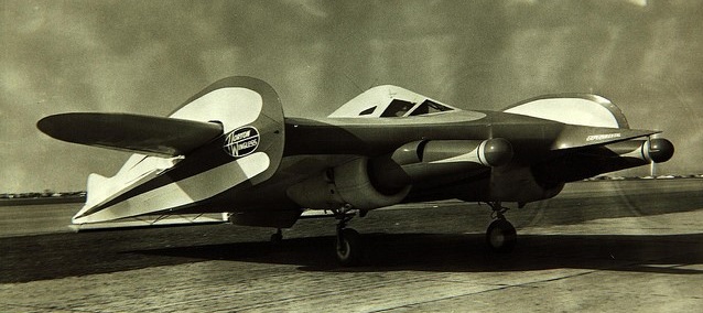
The Horton Wingless aircraft was invented by William Horton of Huntington Beach, California in 1952. He called the strange-looking plane “wingless” because he claimed the entire craft was a simple air foil with vertical fins and utilized all surfaces for lift. Unfortunately, Horton did not have the money to develop it, but was able to get into a partnership with billionaire Howard Hughes and Harlow Curtis.

The aircraft was a welded steel frame covered with a fabric skin and powered by two Pratt and Whitney R985 radial engines. Instead of a long high aspect ratio wing the fuselage was to create the lift and tip plates which he called ‘sealers’ were to tip losses that otherwise plague such airfoils. Essentially it was a highly-modified Cessna UC-78 with a more airfoil-shaped fuselage than wing.

Registered N39C, the aircraft logged around 160 hrs of flight time before Bill Horton had a falling out with Hughes. Horton was railroaded to prison.

Although this innovative prototype flew successfully, no backers were attracted. The venture failed not because the airplane didn’t fly, but because Hughes wanted to take full credit for the patents and production rights, which Horton refused to allow. Hughes sued Horton which effectively stopped any further development of the aircraft. Hughes managed to have the prototype and partially-constructed production version moved to the bone yard at the south end of the Orange Co airport and deliberately burned.

Hornet Microlights Invader 330 / Striker

The Invader 330 is a one plus one derivative of the Invader 440 (side by side one/two seat), using the smaller Robin EC34PM engine and a Flexiform Sky Sails Striker wing.

Engine: Robin EC34PM.
Toothed belt reduction.
Length overall 11.0ft, 3.35 m.
Wing span 34.5 ft, 10.52 m.
Sweep back 15 degs.
Total wing area 200 sq.ft, 18.6 sq.m.
Wing aspect ratio 7.5/1.
Wheel track 4.3 ft, 1.31 m.
Nosewheel diameter overall 16 inch, 41 cm.
Main wheels diameter overall 16 inch, 41 cm.

Hornet Microlights Invader 440 / Dual Striker

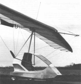
Hornet/Flexiform Sky Sails Invader 440/Dual Striker – A side by side two seat single engined flex wing aircraft with weight shift control. Rogallo wing with keel pocket. Pilot suspended below wing in trike unit, using bar to control pitch and yaw/rod by altering relative positions of trike unit and wing. Wing braced from above by kingpost and cables, from below by cables; bowsprit construction with 65% double surface; pre formed ribs. Undercarriage has three wheels in tricycle formation; steel spring suspension on nosewheel and rubber suspension on main wheels. Push right go left nose¬wheel steering independent from yaw control. Brakes on main wheels. Aluminium tube/ glass fibre trike unit, partially enplosed. Engine mounted below wing driving pusher propeller. All major components made from aircraft quality materials.
The Invader gives weather protection, quick rigging and ease of ground handling a high priority. The wind tunnel developed trike unit is almost fully enclosed, only the sides being open, and is of mono pole construction. The mono pole is an aerofoil rather than the usual round section and is mated to a one piece rear axle instead of the two piece plus tie wire arrangement commonly used with mono poles.
To cope with rough field operation, all three wheels have suspension and in addition the nose wheel geometry is arranged to give a self stabilising effect, so that the aircraft runs true even if the pilot makes a less than perfect touchdown. A hand operated brake is fitted to the main wheels, arranged so that it can be used as a parking brake. The fuel tank is made from aluminium alloy with internal baffles.
Rigging is confined to the wing and is hence claimed to take a maximum of 15 minutes. The trike unit has road tyres on the rear, running on stainless steel axles and taper=roller bearings, so that it can be towed complete on its own wheels. Wing fitment is the Flexiform Skysails Dual Striker, a fast wing which Hornet designer Richard Wolfenden says is well matched to the new trike unit.

Length overall 14.0 ft, 4.27 m.
Height overall 12.5 ft, 3.80m.
Wing span 38.0 ft, 11.58m.
Chord at root 9.0 ft, 2.74m.
Chord at tip 3.5ft, 1.07m.
Dihedral 2 degs.
Sweepback 15 degs.
Keel pocket depth 1.2ft, 0.37m.
Total wing area 250 sq.ft
23.2 sq.m.
Keel pocket area 3.5 sq.ft, 0.33 sq.m.
Wing aspect ratio 6.0/1.
Wheel track 4.3 ft, 1.31 m.
Nosewheel diameter overall 16 inch, 41 cm.
Main wheels diameter overall 16 inch, 41 cm.
Engine: Robin EC44, 50 hp.
Propeller diameter and pitch 60×34 inch, 1.52×0.86m.
Toothed belt reduction, ratio 2.8/1.
Max static thrust 280 lb, 127kg.
Power per unit area 0.20hp/sq.m, 2.2 hp/sq.m.
Fuel capacity 5.0 US gal, 4.2 Imp gal, 19.1 litre.
Empty weight 290 lb, 132kg.
Max take off weight 682 lb, 309kg.
Payload 392 lb, 1.78kg.
Max wing loading 2.73 lb/sq.m, 13.3 kg/sq.m.
Max power loading 13.6 lb/hp, 6.2 kg/hp.
Load factors +4.5, 2.0 design.

Hornet Microlights Supreme 440 / 440 Dual

The Supreme 440 is identical to the 440 Dual except that the chrome plated joint pieces and electric start are fitted as standard.
While some manufacturers of big engined two seat trikes recommend that ballast should be carried when flying solo, Hornet prefer instead to reduce the throttle opening, saying that, thanks to the lift characteristics of the Cutlass CD wing, the solo pilot can take off quite quickly even on part throttle.

440 Dual
Engine: Robin EC44, 45 hp at 6500 rpm.
Propeller diameter and pitch 54 x 36 inch, 1.37 x 0.91 m.
Toothed belt reduction, ratio 2.5/1.
Max static thrust 270 lb, 122 kg.
Power per unit area 0.23 hp/sq.ft, 2.4hp/sq.m.
Fuel capacity 4.8 US gal, 4.0 Imp gal, 18.2 litre in each tank; two tanks.
Empty weight 293 (313) lb, 133 (142) kg.
Max take off weight 685 lb, 311 kg.
Payload 392 lb, 178 kg.
Max wing loading 3.46 lb/sq.ft, 16.9 kg/sq.m.
Max pow¬er loading 15.2 lb/hp, 6.9 kg/hp.
Load factors; >+3.75 ultimate.
Max level speed 60 mph, 97 kph.
Never exceed speed 68 mph, 109 kph.
Max cruising speed 45 mph, 72 kph.
Economic cruising speed 40 mph, 64 kph.
Stalling speed 26 mph, 42 kph.
Max climb rate at sea level 850 ft/min, 4.3 m/s.
Take off distance 45ft, 14m.
Landing dis¬tance 110ft, 35m (without brakes).
Total range at average cruising speed 190 mile, 306 km.

Supreme 440
Engine: Robin EC44, 45 hp at 6500 rpm.
Propeller diameter and pitch 54 x 36 inch, 1.37 x 0.91 m.
Toothed belt reduction, ratio 2.5/1.
Max static thrust 270 lb, 122 kg.
Power per unit area 0.23 hp/sq.ft, 2.4hp/sq.m.
Fuel capacity 4.8 US gal, 4.0 Imp gal, 18.2 litre in each tank; two tanks.
Empty weight 313 lb, 142 kg.
Max take off weight 705 lb, 320 kg.
Payload 392 lb, 178 kg.
Max wing loading 3.56 lb/sq.ft, 17.4 kg/sq.m.
Max pow¬er loading 15.7 lb/hp, 7.1 kg/hp.
Load factors; >+3.75 ultimate.
Max level speed 60 mph, 97 kph.
Never exceed speed 68 mph, 109 kph.
Max cruising speed 45 mph, 72 kph.
Economic cruising speed 40 mph, 64 kph.
Stalling speed 26 mph, 42 kph.
Max climb rate at sea level 850 ft/min, 4.3 m/s.
Take off distance 45ft, 14m.
Landing dis¬tance 110ft, 35m (without brakes).
Total range at average cruising speed 190 mile, 306 km.

Hornet Microlights Skyhook Sailwings 250/Sabre C

Single seat single engined flex wing aircraft with weight shift control. Rogallo wing with keel pocket. Pilot suspended below wing in trike unit, using bar to control pitch and yaw/roll by altering relative positions of trike unit and wing. Wing braced from above by kingpost and cables, from below by cables; floating cross tube construction with 55% double surface enclosing cross tube; pre-formed ribs. Undercarriage has three wheels in tricycle formation; no suspension on any wheels. Push right go left nosewheel steering independent from yaw control. Optional brake on nosewheel. Aluminium tube trike unit without pod (250), with pod and side fairings (250 Executive). Engine mounted below wing driving pusher propeller. All major components made from aircraft quality materials. Front fork assembly made from aluminium alloy.
The 250 is a basic single seat trike unit generally sold with a Skyhook Sailwings Sabre C wing. Other wings offered are Skyhook Sailwings Cutlass C, Airwave Nimrod, Gold Marque Sports Gyr and Flexiform Skysails Striker.
Instead of the usual bolt and saddle washers method, Hornets use tube joint pieces made from external sleeving, welded together in the appropriate shape (T, L or whatever). The tubes are slid inside the joint pieces and retained by aircraft quality bolts or, for less critical applications, stainless steel rivets. Made from steel, the joint pieces have passivated zinc plating for corrosion protection; chromium plating is an option.
A recognition point is the U shaped nose tube, designed to facilitate the fitting of Hornet’s own glass fibre pod. When fitted with this pod plus glass fibre side fairings, the trike unit is known as the 250 Executive. Other options include a nosewheel brake, alloy skis, alloy wheels, an extra fuel tank holding 3.6 US gal (3.0 Imp Gal).

Horn TH-1

February 1997

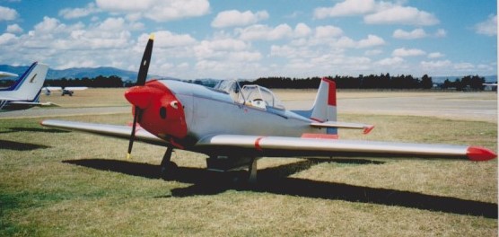
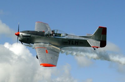
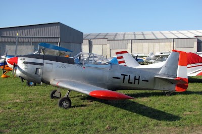
Horn TH 1 ZK-TLH was the result of over forty years of experience in aviation by a Levin pilot, being a low wing monoplane similar in microlight configuration to the Bobcat. Powered by a two cylinder Koenig radial, the TH 1 was undergoing ground trials in 1989.

The single-seat aircraft was built by Tom Horn without plans, and features spoilerons rather than ailerons.

It is surprisingly large for a microlight and was re-powered with a 1.8 litre Subaru engine.

ZK-TLH (c/n MAANZ/423) was first registered to Tom Horn of Levin on 17/4/89.

Tom sold it to his cousin Graham Horn of Taupo on 2 September 2002 although Graham may have been operating it for some time before the change of ownership.

Finally, it was sold to Brian Taylor of Whangarei on 2 August 2004. Brian constructed a new cowling and added a turbo charger to the Subaru engine and has flown it quite a bit around the North of the North Island.

Engine: Konig D-1000.
Seats: 1