Jurca MJ-7 Baby Mustang

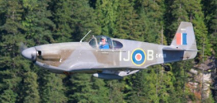
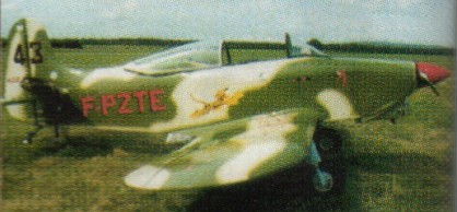
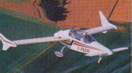
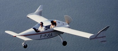
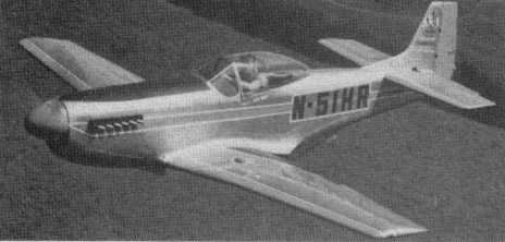
To facilitate homebuilding replicas of fighter planes, designer Marcel Jurca has created a scaled-down ver¬sion of the P-51 Mustang, the Supermarine Spitfire and the Focke Wulf FW-190. The Mustang is available in 2/3 (MJ-7) or 3/4 scale (MJ-77). Only the relative size of a pilot’s head identifies the Baby P-51 from its bigger brother. The ship first flew with a 200-hp Ranger inline engine. Others that can be used include: any of the six-cylinder Rangers, the 125-hp Mènasco, the 130-hp Gipsy Major, the 125 to 160-hp Canadian Rambler, or the General Motors Buick F58. Materials used are wood and fabric.

The Mustang replica is of all-wood construction and uses many components from the aircraft industry. It has a retractable undercarriage and conventional flight control surfaces and flaps. The fuselage, wings and empennage are of sitka spruce framework with a plywood covering and an exterior finish of thin fiberglass. It is powered by a six-cylinder Lycoming aircraft engine.

Although capable of carrying two persons, with the second seat removed and an additional fuel tank installed, the design represents the earlier P-51B with the high rear fuselage, rather than the more common P-51D with a bubble canopy.

The two-thirds scale replica P-51B Mustang is the model MJ-7-G.

Boeve Fiberglass Components Inc offered full kits (1997) for US$35,000. Plans were selling for US$500.

MJ-7
Engine: V8 350/351, 330 hp.
HP range: 200-330.
Height: 8.7 ft.
Length: 22 ft.
Wing span: 24.5 ft.
Wing area: 112 sq.ft.
Weight empty: 1800 lbs.
Gross: 2450 lb
Fuel cap: 52 USG.
Speed max: 300 mph.
Cruise: 255 mph.
Range: 1000 sm.
Stall: 69 mph.
ROC: 2000 fpm.
Take-off dist: 800 ft.
Landing dist: 1000 ft.
Seats: 2.
Landing gear: retractable tail wheel.

MJ-7-G P-51B Mustang
Engine: Lycoming O-540, 260 hp
Maximum speed: 200 mph (322 km/h)
Loaded weight: 1900 lb (862 kg)
Span: 24 ft 9 in (7.5 m)
Length: 23 ft 3 in (7.1 m)
Height: 6 ft 3 in (1.9 m)
Wing area: 114 sq ft (10.6 sq m)

Wingspan 25’l0”
Length 22’4”
Gross Wt. 2000 lb
Empty Wt. 1175 lb
Fuel capacity 30 USG
Top speed 225 mph
Cruise 175 mph.
Stall 65 mph.
Range 570 miles
Takeoff run 900 ft
Landing roll 800 ft

Boeve Fibreglass Components MJ-7
Engine: V8 351/350, 330 hp
HP range: 200-330
Height: 8.7 ft
Length: 22 ft
Wing span: 24.5 ft
Wing area: 112 sq.ft
Empty weight: 1800 lb
Gross weight: 2450 lb
Fuel capacity: 52 USG
Top speed: 300 mph
Cruise: 235 mph
Stall: 69 mph
Range: 1000 sm
Rate of climb: 2000 fpm
Takeoff dist: 800 ft
Landing dist: 1000 ft
Seats: 2
Landing gear: tailwheel retractable
G limits: +6/-4

Jurca MJ-5 Sirocco

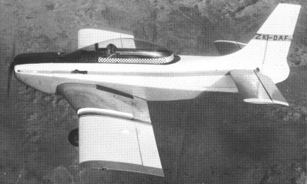
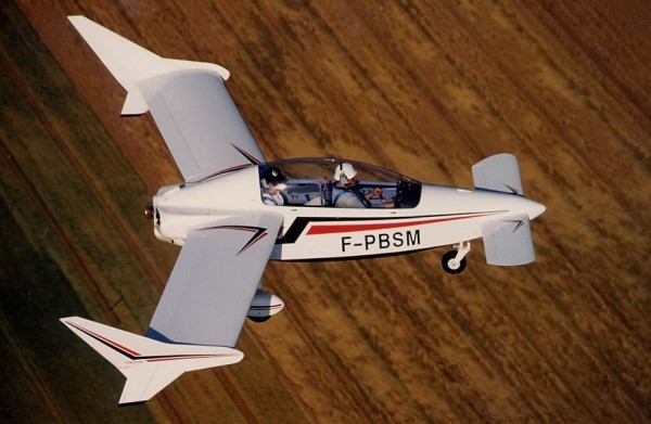
The prototype MJ.5 Sirocco tandem two-seat aerobatic monoplane, built in France, was first flown in 1962. The Sirocco, an all-wood, fiberglass or fabric-covered low-wing design, can be identified by its rooster tail. The Sirocco sports retractable landing gear.

Flying with or without wing end plates, the inboard wing fence is employed in either case. The prototype flew with a Hirth engine, but 90 to 100 hp Continental or 105 hp Potez engine may be fitted. The original prototype was still flying after 30 years.

Gallery

Engine: Lycoming, 160 hp.
HP range: 125-200.
Weight empty: 1260 lbs.
Gross: 1860 lbs.
Height: 8.5 ft.
Wingspan: 21.45 ft
Wing area: 107.6 sq.ft.
Speed max: 196 mph.
Cruise 162 mph.
Stall: 64 mph.
ROC: 1850 fpm.
Service ceiling: 16,400 ft.
Seats: 2.
Landing gear: nose or tail wheel.
Takeoff run 820 ft.
Landing roll 750 ft.
Range 570 sm.

Engine: Lycoming, 150 hp.
Cruise: 115 kts.
Wing span: 23ft 4in.
Length: 21 ft.
MAUW: 1500 lbs.
Fuel cap: 25.5 Imp Gal.

Engine: Lycoming O-320, 160 hp
Wing span: 7.02 m
Wing area: 11 sq.m
MAUW: 840 kg
Empty weight: 560 kg
Fuel capacity: 170 lt
Max speed: 300 kph
Cruise speed: 240 kph
Minimum speed: 100 kph
Climb rate: 11 m/s
Seats: 2
Fuel consumption: 45 lt/hr
Plan price (1998): US$500

Jurca MJ-3 Dart

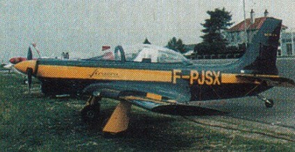
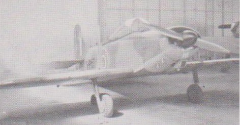
The Jurca MJ-3 Dart is composed of the MJ-2 fuselage and MJ-5 wing with retractable gear, split flaps. Power range is from 115 to 180 hp.

Gross Wt. 1350.
Empty Wt. 1050.
Fuel capacity 16.5 Imperial gals.
Wingspan 20’l0”.
Length 19’.
Top speed 154 mph.
Cruise speed 70%: 142 mph
Cruise economy 135 mph
Stall (flaps) 55 mph
Takeoff run 750 ft
Landing roll 1000 ft
Endurance 2 hr 45 min

Jurca MJ-2 Tempete

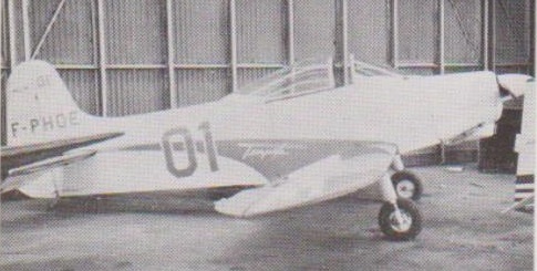
Marcel Jurca incorporated many Jodel Components in the design of the MJ-2 Tempete. The Tempete is a cantilevered low-wing monoplane that can be fitted with engines ranging in horsepower from 65 to 125.

MJ-2 Tempete prototype – Guyancourt, 1965

The single-seat wood/fabric aerobatic MJ.2 Tempete was first flown in 1956.

The standard version is powered by a 65-hp engine. Another common version powered by a 90-hp engine cruises at 120 mph and climbs to 3280 in three minutes.

MJ-2 LX-PUT cn 18, Findel, Luxembourg 5 August 1975. Built as F-PNUD Continental O-200-A

Engine: Lycoming, 110 hp.
HP range: 65-180.
Height: 7.8 ft.
Length: 18.5 ft.
Wing span: 19.5 ft.
Wing area: 85.9 sq.ft.
Weight empty: 639 lbs.
Gross: 950 lbs.
Fuel cap: 16 USG.
Speed max: 120 mph.
Cruise: 102 mph.
Range: 375 sm.
Stall: 62 mph.
ROC: 555 fpm.
Take-off dist: 820 ft.
Landing dist: 800 ft.
Service ceiling: 11,500 ft.
Seats: 1.
Landing gear: retractable tail wheel.

Junqua-Diffusion Ibis RJ.03

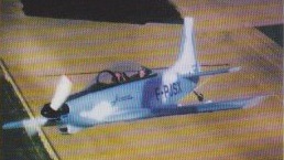
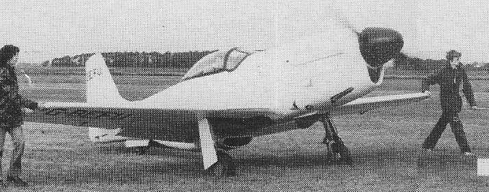
Developed from the RJ.02 Volucelle, the RJ.03 Ibis tandem two-seat canard monoplane, first flown 1991, was offered in plans form for home construction.
In March 1992 the Ibis received its French certification at Pau airport in France.
Totally enclosed in wood (spruce, douglas fir), it requires no fabric coverings.
By utilizing a combination of “Styrodur” (polystyrene) with identically-matching plywood ribs and depression-bonding of surface-coatings, its surface finish matchs that of synthetic-fibre aircraft.

Fitted with “flaperons” on the wings, its approach speed is identical to that of classic aircraft bearing the same load per sq.m. With little nosing-up during approach, rearward and forward visibility is excellent. Due to the use of a nonlaminar surface on the canard, flights are not affected by rain.

The fuel consumption is only 13 l/h at 200 km cruising speed or 10 l/h at 180 km. The rate of climb is 700 fpmat max. take-off weight with only 60 hp.

The IBIS is designed to be used with different types of engines (VW-1830cc, VW-1915cc, French JPX-475T, Australian JABIRU 2200cc, Limbach-2000 EC) and can be fitted with certain types of rotary engines (MID-WEST).
The structure comprises 7 frames, 4 longerons and diagonal struts. It is covered with plywood and requires no padding. The fuselage is assembled on the model plane principle, upside down on a table, and after construction of the different frames. The 150 pages handbook, included in the instruction document pack, will give you all the necessary explanations as regards: construction, adjustments and test flight techniques.

The canard wing is rectangular, with no twisting or dihedral angle. It has round tips which are bevelled on the underside. The trailing edge is fitted with a built-in slotted flap, which runs along the whole length of the wing. The canard structure consists of a “box-form spar” the same thickness as the profile and which joins 8 identical plywood former-ribs. The whole structure is filled with “Styrodur” foam, and covered with thin plywood which is glued by suction using the same technique as that employed in the construction of certain model planes.
The wing spar is a “box-form” construction and consists of two caps braced together by means of plywood strips on each side. It is in one single piece, at an angle to the airframe. Width and height are constant along whole thickness of the profile. There is no dihedral angle or twisting. All wing ribs are identical, and are in plywood. They are made in a single operation using a metal template and a joiner’s spindle moulding machine. This can be done very quickly. The wing is filled with blocks of “styrodur” foam hollowed out to allow passage of flight control linkages and is covered with thin plywood glued by suction. This method represents a saving of circa 40% on the production time required for standard wood and fabric wing construction. The wing can be dismantled only for major overhaul.
Each stabilizer consists of two half-stabilizers made of main plywood longerons and 5 plywood ribs. Thc stabilizers are completely filled with “styrodur”, and covered with glued plywood. The rudders are incorporated in the profile of the stabilizers.
The cabin is heated. Internal luggage stowage is behind the passenger’s head. The one-piece canopy, opens laterally.
The front undercarriage is mounted on a steering wheel, and is connected to the rudder dual controls; it is not retractable. It is made of steel tubes and fitted with a wheel mounted on a rocker, rubber shock absorbers with brakes on the rear-weels. The main undercarriage is made of glued laminated plywood, for weight, easy assembling and low cost. It is highly efficient even on grass runways.
The dual flight control system is the “rigid linkage” type with ball, bell-crank levers and rod connecting joints. The steering and rudder controls are the only system making use of cables. Flight control of the plane is performed through: flaperons (flaps/ailerons) running the whole length of the main wing span, elevator on the canard wing, rudders on stabilizers. The IBIS is flown in a totally classic way.
Fuel tanks are in epoxy resin and are incorporated in the leading edge of the wing. They have a capacity of 60 litres; they are equipped with a feed-tank and have a single refuelling point on the wing or on the luggage hold. The tanks are fitted with an electric fuel gauge and with a single pipe leading from the lower part of the feed-tank. There is no manual system for transferring fuel.
The IBIS plane has been designed for use with VW (Volkswagen) engines in the 60 to 80 HP range, i.e. engines of at least 1830 CC or any more powerful VW engine. Any four stroke four cylinder engine, without reducing gear, weighing 75 kg or less, in good working order (and roughly equivalent to the VW or up to 20 kg lighter) presently in use or coming on line, can be mounted on the IBIS.
It is also possible to use the French engine “JPX 4T 75A” 80 HP, the German “LIMBACH 2000 EC” 68 HP or Australian “JABIRU 2200” 80 HP. All of these engines are without a reduction gearbox.
A two-stroke engine is not recommended as its specific consumption is much greater than that of the four-stroke engines. Some rotary engines can also be considered as alternative solutions. The 65 HP Continental engine is too heavy.
Plans (set of 12 drawings and a 160 pages contruction handbook) of the IBIS aircraft are available in French and English version.
Estimated construction time is put at 2200 hours.
The IBIS RJ03 is classified in a “light aircraft category”. It cannot be modified as “ultra-light”.

Engine: VW
Wing span: 6.3 m
MAUW: 470 kg
Empty weight: 260 kg
Fuel capacity: 60 lt
Max speed: 250 kph
Cruise speed: 203 kph
Minimum speed: 95 kph
Climb rate: 3.5 m/s
Seats: 2
Plan price (1998): 3000 F

Engine: VW, 60 hp.
HP range: 60-80.
Wing span: 6.30 m / 20.66 ft
Length: 4.90 m / 16 ft.
Height: 5.6 ft.
Wing area: 52 sq.ft.
Vertical stabilizer height: 1.76 m / 5.6 ft
Fuselage width: 0.64 m / 26 in
Cabin height: 1.04 m / 3.15 ft
Cabin width at pilot elbow: 0.64 m / 26 in.
Max. take-off weight: 470 kg / 1034 lbs
Weight empty: 260 kg / 572 lbs.
Fuel capacity: 60 lt / 16.2 US.G
Payload (full fuel): 170 kg / 374 lbs
Front pilot weight limits: 65-95 kg / 143-209 lb
Vmo / Vne: 161 mph / 260 km/h / 140kts
Normal cruise 65%: 200 km/h / 108 kt / 124 mph
Long range cruise: 180 km/h / 97 kt / 112 mph
Max. range: 900 km (485 nms) + VFR reserves – 559 sm
Approach speed: 120 km/h / 65 kts / 74 mph
Stall speed: 95 km/h / 52 kts / 59 mph
ROC: 650 fpm.
Vz: 3.5 m/s
Takeoff distance: 1050 ft
Landing distance: 1500 ft
G-loading: +4.5 and -3.0
Seats: 2 tandem.
Landing gear: nose wheel.

Engine: VW 1835 cc
Wing span: 6.30 m / 20.66 ft
Length: 4.90 m / 16 ft.
Height: 5.6 ft.
Wing area: 52 sq.ft.
Vertical stabilizer height: 1.76 m / 5.6 ft
Fuselage width: 0.64 m / 26 in
Cabin height: 1.04 m / 3.15 ft
Cabin width at pilot elbow: 0.64 m / 26 in.
Climb rate: 700 fpm at M.T.O. weight.
Fuel capacity: 60 lt / 16.2 US.G

Junqua-Diffusion RJ.02 Volucelle

In 1987, Roger Junqua and his son Jean-Claude presented a small, all-wood two seater canard at the International Amateurs Builders air show in Brienne-le-Chateau in France.
The “VOLUCELLE”, as it was called, with its futurist lines, after testing, turned out to be an excellent airplane. However, it remained a prototype which was used as a research and test-bed airplane for the development of the “IBIS”.

Junkers Jumo 223 / Jumo 224

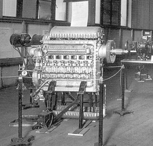
The Junkers Jumo 223 was an experimental 24-cylinder aircraft engine based on the Junkers Jumo 205. Like the Jumo 205, it was an opposed piston two-stroke diesel engine. It had four banks of six cylinders in a rhomboid configuration, with four crankshafts one at each vertex of the rhombus, and 48 pistons. It was designed for a power of 2,500 horsepower at 4,400 rpm, and weighed around 2,370 kg.

Only one example is known to have been built. It is rumoured to have been taken to Moscow after the war, where development may have continued.

In 1942 the 223 was abandoned in favour of an even larger engine, the Jumo 224 with an intended output power of 4,500 horsepower.

The Jumo 223 series was influential to the successful three-crankshaft Napier Deltic engine.

Junkers Jumo 222

The Jumo 222 was a high-power multiple bank in-line piston aircraft engine design from Junkers, designed under the management of Ferdinand Brandner of the Junkers Motorenwerke. Such was the performance of the engine compared to contemporary designs that many developments of wartime Luftwaffe piston-engined aircraft designs were based around it, at least as an option. The design failed to mature even after years of intensive development, dooming the entire Bomber B program along with it. Only a small number were built, never leaving the prototype phase, but the design nevertheless continued appearing, endlessly, on proposals for new Luftwaffe multi-engined designs long after most had given up hope it would ever work.

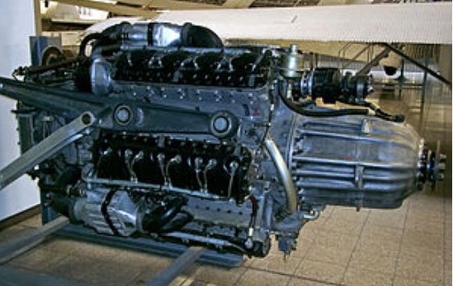
Design work on the Jumo 222 started in 1937. The engine was configured with six inline cylinder banks spaced at equal angles around the crankcase, each bank having four cylinders each. The engine looked like a radial due to the arrangement, but the internal workings were more like a V engine with crossflow heads, and it was liquid-cooled like most inlines. Looking at a complete Jumo 222 from a “nose-on” view, the half-dozen cylinder banks were arranged at 60° equal angles from each other, such that neighbouring banks had their exhaust ports (at the “60°, 180° & 300°” spaces) and intake ports (at the “0°, 120° & 240°” spaces) facing each other, resulting in simpler “plumbing” from the rear-mounted supercharger and resulting in only three sets of exhaust headers. The trio of exhaust header sets would have been most likely present at the bottom of an engine nacelle, and on the upper quarters to either side (appearing like the exhausts for many Allied “upright” V-style aviation engines) for the shortest possible exhaust outlet routing.

Each cylinder had two intake valves and a single sodium-cooled exhaust valve, a high-pressure fuel injector between the intakes, and two spark plugs. With a bore and stroke of 135 mm (5.3 in), the original Jumo 222A/B engine design had a displacement of 46.4 L (2,831.5 in³), in the same general displacement class as the Double Wasp American eighteen cylinder air-cooled radial of 1939/40 origin. The 222A/B model was forced to run at a fairly low 6.5:1 compression ratio, the best possible given the low-octane fuels available in Germany, but by increasing the speed of the engine to 3,200 rpm, the 222 delivered 1,850 kW (2,500 hp) at takeoff. The only disappointing feature was the simple, single-stage two-speed supercharger, but even with this limitation, the engine still generated 1,641 kW (2,200 hp) at 5,000 m (16,400 ft). The dry weight was 1,088 kg (2,399 lb), only some 17 kg (39 lb) heavier than the air-cooled Double Wasp.

Compared to the contemporary BMW 801 and Daimler-Benz DB 605, the 222 was a huge leap in performance. It had only a slightly larger displacement figure than the 801’s 41.8 L (2,550.8 in³), and about ¼ more than the 605’s 35.7 L (2,178.5 in³), but delivered considerably more power, 1,850 kW (2,500 hp) compared to 1,193 kW (1,600 hp) in the 801 and 1,119 kW (1,500 hp) in the 605. That represents 40 kW/L for the 222, while only 29 kW/L for the 801, and 31 kW/L for the 605. Even more impressively the power-to-weight ratio was 1.7 kW/kg (1.04 hp/lb) for the 222, whereas the 605 delivered an otherwise excellent 1.4 kW/kg (0.88 hp/lb), and the 801 a fairly poor 1 kW/kg (0.60 hp/lb). The 222 also had similar exterior dimensions as these smaller engines, 1.16 m (3.81 ft) across compared to 1.27 m (4.17 ft) for the 801, and 2.4 m (7.9 ft) long compared to 2.3 m (7.5 ft) for the 605.

The comparison was even more favourable against other high-power engines under development. The cumbersome DB 606, the first-ever “high-output” powerplant developed by the German aviation engine industry starting in February 1937, consisted of two DB 601’s mounted to a single reduction gear case on their front ends, that delivered 1,790 kW (2,400 hp) from a whopping 1,515 kg (3,340 lb), and was 2.1 x 1.6 x 1.1 m (6.9 x 5.2 x 3.6 ft) in size. Their troubled use and deficient installation design in the He 177, Germany’s only heavy bomber aircraft to see production and front-line service, prompted Reichsmarschall Hermann Göring to derisively label them in the late summer of 1942 as “welded-together engines”. Conversely, the RLM was excited by the possibilities of the much more compact Jumo 222’s design features, and the X engine configuration, 24 cylinder DB 604, of similar weight and displacement to the 222A but with somewhat lower specific power output. The RLM based their entire Bomber B program around pairs of these engines, which would deliver a bomber with the warload of the He 177 and even better speed than the Ju 88, a truly universal design.

The first prototype engine ran on April, 24th 1939, and was later air-tested on the nose-engine mount of a Ju 52. Production called for two primary models, the 222A and 222B, which differed only in the direction that they spun, intended to be used for left and right-hand engines on twin-engine designs. However, continued testing went poorly, and Junkers eventually decided it was best to stop development of these “Series I” engines and move onto a modified “Series II”. The new 222A-2 and B-2 ran at a slightly slower rpm but had slightly larger cylinders of 140 mm/5.5 in bore (49.88 litres, 3043.86 in³) for the same net performance, while the A-3 and B-3 used a different supercharger for better performance at higher altitudes. Both continued to prove unreliable, and were fitted only experimentally.

By late 1941, Junkers decided the best course of action was to make more radical changes to the design, and introduced the 222C and 222D models. With a new bore and stroke of 145×140 mm (5.7×5.5 in), the engine displacement increased a second time, to 55.5 L (3,386.8 in³), just very slightly larger than the contemporary Wright Duplex Cyclone American 18-cylinder air-cooled radial engine, which at the time was having its own significant problems ironed out, partially from the use of combustible magnesium-alloy metal for its crankcase. Back at the original 3,200 rpm, the Jumo 222 C/D models could deliver just under 2,200 kW (3,000 hp) when they started running in the summer of 1942. However, the problems were not cured, and only a handful were built. The RLM had been waiting for three years at this point, and eventually gave up and had all designs based on it look for alternate engines. Later that year, they gave up on that as well, and cancelled the entire Bomber B program outright.

Junkers still did not give up. Using the original 46.4 litre displacement A/B design, they added a new two-stage supercharger including a trio of aftercoolers, one per pair of neighboring cylinder banks for high-altitude use, producing the 222E and F-series. Although sea-level performance was unchanged, the engine was able to produce 1,439 kW (1,930 hp) at 9,000 m (29,530 ft). By this point it appeared that the problems were finally being worked out, but bombing of the Junkers Motorenwerke’s headquarters factories in Dessau made production almost impossible. A final attempt for even higher altitude performance resulted in the turbocharged 222G and H, built only to the extent of a few testbed prototypes.

The Jumo 222 was a massive and very costly failure. 289 examples of the Jumo 222’s were built in total, none of which saw active service. It also served to seriously hamper Luftwaffe piston-engined designs from 1940 to 1942, while many personnel within the Luftwaffe’s government-operated technology development offices (like Oberst Edgar Petersen’s chain of several Erprobungsstelle installations) and German military aviation corporate engineering departments waited for the Jumo 222 to finally start working. Meanwhile, all calls for four-engine adaptations in place of twin-engine Jumo 222 powered designs were rejected because it was felt it would place too much strain on the German engine industry. In the end there was nothing to show for it, and late in the war the Luftwaffe was flying barely updated versions of their original pre-war designs.

Variants:
None of the JuMo 222 variants achieved operational service.
JuMo 222A-1
JuMo 222A-2
JuMo 222A-3
JuMo 222B-1
JuMo 222B-2
JuMo 222B-3
JuMo 222C
JuMo 222D
JuMo 222E
JuMo 222F
JuMo 222G
JuMo 222H

Specifications:
Jumo 222A
Type: 6-bank, 24-cylinder supercharged liquid-cooled in-line aircraft engine
Bore: 135 mm (5.3 in)
Stroke: 135 mm (5.3 in)
Displacement: 46.5 L (2,830 in³)
Length: 2,400 mm (94.5 in)
Diameter: 1,160 mm (45.7 in)
Dry weight: 1,088 kg (2,399 lb)
Valvetrain: Two intake valves and one sodium-cooled exhaust valve per cylinder
Supercharger: Single-stage two-speed centrifugal type supercharger
Fuel system: Fuel injection
Cooling system: Liquid-cooled
Power output:
1,838 kW (2,465 hp) at 3,200 rpm for takeoff
1,397 kW (1,870 hp) cruise
Specific power: 39.5 kW/L (0.87 hp/in³)
Compression ratio: 6.5:1
Specific fuel consumption: 0.29 kg/(kW·h) (0.477 lb/(hp·h))
Power-to-weight ratio: 1.69 kW/kg (1.03 hp/lb)
Junkers Jumo 205 / Jumo 207

Jumo 205

The Junkers Jumo 205 aircraft engine was the most famous of a series of Diesel engines that were the first, and for more than half a century the only, successful aircraft Diesel engines. The Jumo 204 first entered service in 1932. Later engines in the series were styled Jumo 206, Jumo 207 and Jumo 208, and differed in stroke and bore and supercharging arrangements. In all more than 900 of these engines were produced.

These engines all used a two-stroke cycle with twelve pistons sharing six cylinders, piston-head to piston-head in an opposed piston configuration. This unusual configuration required two crankshafts, one at the bottom of the cylinder block and the other at the top, geared together. The pistons moved towards each other during the operating cycle. Intake and exhaust manifolds were duplicated on both sides of the block. There were two cam-operated injection pumps per cylinder, each feeding two nozzles, for 4 nozzles per cylinder in all.

As is typical of two-stroke designs, the Jumos used fixed intake and exhaust ports instead of valves, which were uncovered when the pistons reached a certain point in their stroke. Normally such designs have poor volumetric efficiency because both ports open and close at the same time and are generally located across from each other in the cylinder. This leads to poor scavenging of the burnt charge, which is why valve-less two-strokes generally produce smoke and are inefficient.

The Jumo solved this problem to a very large degree through clever arrangement of the ports. The intake port was located under the “lower” piston, while the exhaust port was under the “upper”. The lower crankshaft ran eleven degrees behind the upper, meaning that the exhaust ports opened and, even more importantly, closed first, allowing proper scavenging. This system made the two-stroke Jumos run as cleanly and almost as efficiently as four-stroke engines using valves, but with considerably less complexity.

There is some downside to this system as well. For one, since matching pistons were not closing at quite the same time, but one ran “ahead” of the other, the engine could not run as smoothly as a true opposed style engine. In addition, the power from the two opposing crankshafts had to be geared together, adding weight and complexity, a problem the design shared with H block engines.

In the Jumo, these problems were avoided to some degree by taking power primarily from the “upper” shaft. All of the accessories, such as fuel pumps, injectors and the scavenging compressor, were run from the lower shaft, meaning over half of its power was already used up. What was left over was then geared to the upper shaft, which ran the propellers. In all, about three-quarters of the power to the propellers came from the upper crankshaft.

In theory, the flat layout of the engine could have allowed it to be installed inside the thick wings of larger aircraft, such as airliners and bombers. Details of the oil scavenging system suggest this was not possible and the engine had to be run “vertically”, as it was on all designs using it.

A twelve cylinder version, the Jumo 218, was designed but never built, while a single 24-cylinder 4-crankshaft Junkers Jumo 223 was built and tested.

The Jumo 204 and 205 were licensed to Napier & Son, who built a small number as the Napier Culverin just prior to the war. After the war, they mounted three Culverins in a triangle layout to produce the Napier Deltic, which was for some time one of the most powerful and compact diesel engines in the world. Work on this engine started in 1947 and engines were running by 1950.

The Jumo 205 powered early versions of the Junkers Ju 86 bomber, but was found too unresponsive for combat and liable to failure at maximum power, common for combat aircraft. Later versions of the design also used the engine for extreme high-altitude use. It was far more successful as a power unit for airships, for which its characteristics were ideal, and for non-combat applications such as the Blohm & Voss Ha 139 airliner.

Applications:
Blohm & Voss BV 138
Blohm & Voss Ha 139
Blohm & Voss BV 222
Dornier Do 18
Dornier Do 26
Junkers Ju 86

Specifications:
Jumo 205 A
Type: Six-cylinder 12-piston liquid-cooled opposed piston inline two-stroke diesel engine
Bore: 105 mm (4.13 in)
Stroke: 160 mm (6.3 in)
Displacement: 16.63 L (1,015 in³)
Length: 76.5 in (1,934 mm)
Width: 21.54 in (547 mm)
Height: 52.17 in (1,325 mm)
Dry weight: 595 kg (1,312 lb)
Fuel system: Fuel injection
Fuel type: Diesel
Oil system: Forced with one pressure and two scavenge pumps
Cooling system: Liquid-cooled
Power output: 647 kW (867 hp) at 2,800 rpm
Specific power: 39.0 kW/L (0.86 hp/in³)
Compression ratio: 17:1
Power-to-weight ratio: 1.09 kW/kg (0.66 hp/lb)

Junkers Jumo 204 / Fo4 / SL1 / Jumo 4 / Napier Culverin

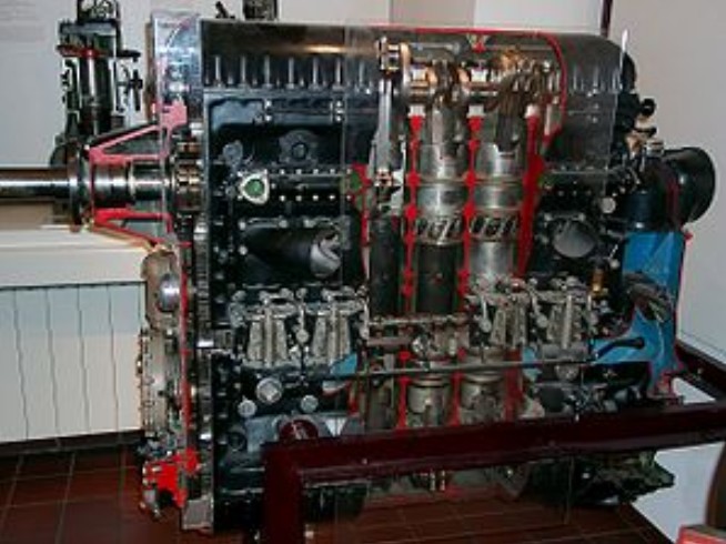
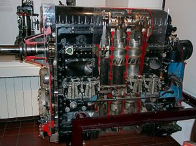
Cut away view of a Jumo 205, a decreased capacity version of the Jumo 204

Development of the Junkers diesel engines started in the 1920s with the Junkers Fo3 and Junkers Fo4/Junkers SL1. The Fo4 was re-designated Junkers 4, which in turn was re-designated Junkers 204 by the Reichsluftfahrtministerium (RLM).

These engines all used a two-stroke cycle with six cylinders and twelve pistons, in an opposed piston configuration with two crankshafts, one at the bottom of the cylinder block and the other at the top, geared together. The pistons moved towards each other during the operating cycle. Intake and exhaust ports were duplicated at both ends of the block. There were two cam-operated injection pumps per cylinder, each feeding two nozzles, totaling four nozzles per cylinder.

As is typical of two-stroke designs, the Jumos used fixed intake and exhaust ports instead of valves, which were uncovered when the pistons reached a certain point in their stroke. Normally such designs have poor volumetric efficiency because both ports open and close at the same time and are generally located across from each other in the cylinder. This leads to poor scavenging of the burnt charge, which is why valve-less two-strokes generally run smoky and are inefficient.

The Jumo 204 solved this problem to a very large degree through a better arrangement of the ports. The intake port was located under the “lower” piston, while the exhaust port was under the “upper”. The lower crankshaft ran eleven degrees behind the upper, meaning that the exhaust ports opened first, allowing proper scavenging. This system made the two-stroke Jumos run as cleanly and almost as efficiently as four-stroke engines using valves, but with considerably less complexity.

The Jumo 204 (originally designated Jumo 4) was test flown in early 1929 installed in a Junkers G 24. The Jumo 204 first entered service in 1932.

Later engines in the series were designated Jumo 205, Jumo 206, Jumo 207 and Jumo 208, they differed in stroke and bore and supercharging arrangements.

The Jumo Fo3 and 204 were licensed to Napier & Son, who built a small number as the Napier Culverin just prior to the war. Late in the war, they mounted three Culverins in a triangle layout to produce the Napier Deltic, which was for some time one of the most powerful and compact diesel engines in the world.

First run in 1934, the Culverin name is derived from the French word, culverin, for an early cannon or musket. First flown in 1938 using a Blackburn Iris V biplane flying-boat aircraft, the engine went into production for use in the Fairey III biplane.

Variants:
Mo3
A research diesel engine for test bed use only, the Mo3 was a four cylinder, (eight piston), opposed-piston engine designed to run horizontally. Tested from 1913, the problems found in testing the Mo3 were progressively solved after WWI with the Fo3 and later opposed piston diesels.

Fo3
From 1924, Junkers experimented with the Fo3, A vertical 5-cyl. opposed-piston diesel, which ran on a test bed in the summer of 1926, developing 620 kW (830 hp) at 1,200 rpm. Mostly successful, the Fo3 did highlight the need for accurate dynamic balancing of the rotating components.

Fo4
(a.k.a. SL1) The Fo4, benefiting from the experience gained with the Fo3, was a six-cylinder opposed-piston diesel engine, tested from 1928 and flown in the nose of a Junkers G.24 from 30 August 1929.

Jumo 4
After the successful bench runs and flight tests, the Fo4 was refined into the certicated Jumo 4, enjoying limited success powering re-engined Junkers F24kay airliners of Deutsche Luft Hansa, remaining in service until 1939.

Jumo 204
Later production of refined Jumo 4s, designated Jumo 204 in three sub-variants: 204A, 204B,and 204C, differing in airscrew drive arrangements.

Napier Culverin
Licensed built version of the Junkers Jumo 204 six-cylinder vertically opposed liquid-cooled diesel aircraft engine built by Napier & Son.

Applications:
Junkers F.24kay
Junkers Ju 52
Junkers Ju 86
Junkers G.38
Blohm & Voss BV 138
Blackburn Iris V
Fairey III

Specifications:
Jumo 204
Type: Six-cylinder 12-piston liquid-cooled opposed piston inline two-stroke diesel engine
Bore: 120 mm (4.72 in)
Stroke: 210 mm (8.27 in)
Displacement: 28.5 l (1,739 in³)
Length: 1,260 mm (49.61 in)
Width: 510 mm (20.08 in)
Height: 1,510 mm (59.45 in)
Dry weight: 750 kg (1,653 lb)
Power output: 552 kW (740 hp) at 1,800 rpm
Specific power: 19.3 kW/l (0.42 hp/in³)
Compression ratio: 17:1
Specific fuel consumption: 212 g/(kW•h) (0.35 lb/(hp•h))
Power-to-weight ratio: 0.74 kW/kg (0.45 hp/lb)

Napier Culverin
Type: 12-piston 6-cylinder vertical opposed-piston liquid-cooled diesel engine.
Bore: 4.75 in (120.65 mm)
Stroke: 8.25 in (209.55 mm)
Displacement: 1,737 cu in (28.5 lt)
Dry weight: 1,785 lb (809.6 kg)
Valvetrain: Piston ported
Fuel system: Fuel injected
Fuel type: Diesel oil
Cooling system: Liquid cooled
Reduction gear: Spur geared, reduction ratio 0.6935:1, right hand tractor
Starting system: Compressed air starter
Power output: 821 hp at 2,050 rpm
Power-to-weight ratio: 0.46 hp/lb