Lancair Legacy

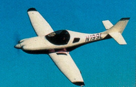
The successor to Lancair’s two-place line, the Legacy represents the culmination of more than a decade of research, testing and invaluable input from Lancair builders and fliers. Redesigned from the tail forward, it’s bigger, faster and easier to build.
Lancair designed a new wing planform, and to keep area to a minimum, the wing has a double taper to maximize the lift distribution from root to tip. This eliminates all “washout” and creates extensive laminar flow across more than 50% of the surface. The low-drag laminar “bucket” is also wider than before, further increasing overall performance. The result is very carefully “tuned” wing design, which enhances overall aircraft performance.
A relatively thick chord was employed which aids strength while providing room for adequate fuel (up to 66 gallons). This wing also had to swallow the new larger 5.00 x 5 main gear ties without gear door modifications.
The addition of simplified Fowler flaps further increases the wing’s maximum lift coefficient to enhance this low speed handling.

Lancair engineers completely redesigned the the cabin. A wider and taller cabin now offers more shoulder and headroom. Plus, the larger canopy affords unobstructed visibility and outstanding views in all directions. The roomier baggage area makes it possible to stow everything including golf bags and fishing rods.
The Lancair Legacy offers a 43.5-inch cabin width and 44.5-inch height. The pilot and passenger sit in a normal upright position.

The Legacy’s new fuselage is now able to accommodate a 310 h.p. Continental 1O-550. The Legacy will cruise at 280 mph at 10,000 ft. The Legacy’s climb rate is +2200 fpm.
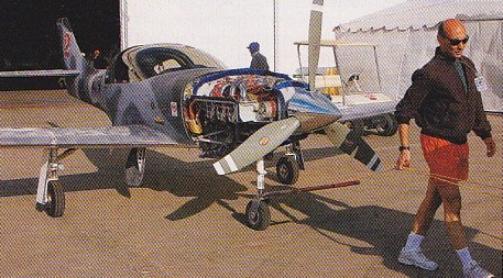
To trailer the aircraft, the wings can be removed while the aircraft remains fully on its landing gear. Lancair also works closely with the engineers at Teledyne Continental Motors and Textron Lycoming, Hartzell and MT-Propellers to refine the power plant installation and to perfect the union of engine and propeller to the airframe. Many engine options – from 160 hp to 310 hp – can be accommodated including the Lycoming 1O-360 and the Continental 1O-550.

Fuel is carried in the wings – the fuel tanks are integral within the wing bays. Standard fuel tanks have a 66 US gallon capacity. The fuel selector is per FAA standards, allowing for either left, right or off. (The “both” position is not recommended for low-wing aircraft.) As a safety feature, each wing tank incorporates a “slosh bay” to prevent unporting of the fuel pickup in the event of uncoordinated maneuvers such as during slips. The fuel valve (for Continental engines) also returns “vapor,” or return fuel, back to the fuel tank in use. Custom fuel quantity monitoring systems are available as options.

Sitting three inches taller than the 320/360 for more ground and prop clearance, the Legacy’s main landing gear incorporates air/oleo struts with 5.00 x 5 main gear tires. The nose gear is also the premium air/oleo strut with internal viscous shimmy dampening. Protected from the environment, the internalized dampening system provides longer service life, and there are no scissor links to wear out. Steering is accomplished by differential braking, and the rudder becomes effective at taxi speeds as low as 20 m.p.h. A tire guide strap assures proper retraction of the nose wheel into the gear. The retraction method is Lancair’s electro/hydraulic system.

The Legacy’s major airframe is constructed of composite materials. Cured at 270 degrees Fahrenheit under vacuum pressure, these composites are NASA tested.

The high-temperature, pre-impregnated carbon fiber and/or fiberglass systems combined with Nomex/honeycomb core materials allows the Legacy’s sculptured fuselage and double-taper wing to have no drag-producing rivets or lap joints. Corrosion resistant, a nearly infinite fatigue life and virtually non-flammable, composite materials also extend the life of the airframe.

Lancair’s fastbuild kit, accessory catalog service, avionics shop, free technical assistance and builder assist program make the assembly process quick and efficient enjoyable. To make wing assembly simpler, the main spars and the ribs are “pre-installed” into the wing skins. Then, wing attachments bushings that accurately establish the wing dihedral are pre-installed. Flaps and ailerons are completed and most of the control systems are installed.

Darryl Greenamyer raced a Legacy in the Sport Class at the 40th Annual Reno Races. Greenamyer achieved 350mph during qualifying laps and won the Gold race.
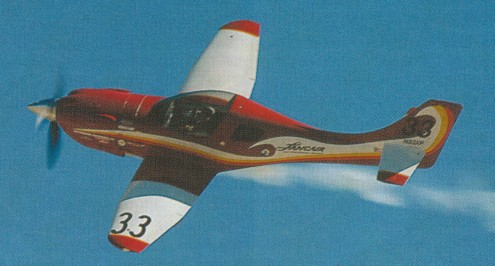
Legacy’s achieved 1st, 2nd, and 3rd in the Gold Class and 1st in the Silver Class that year.

LEGACY FG
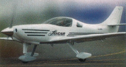
The Legacy Fixed Gear kitplane is a simple, economical version of the retractable gear Legacy. Other than the permanent down and locked wheels, the fixed gear Legacy is very similar to its retractable gear counterpart. Sharing the fuselage, wing and tail with the retractable gear Legacy, the Legacy FG is designed to accept a four cylinder Lycoming engine with a conventional instrument panel to lower costs and reduce build time. Fitted with a 210 hp Lycoming IO or TNIO-390X powerplant, the Legacy FG has a typical cruise of over 225 mph and a range of more than 1,300 statute miles. The FG was available in a carbon version that will accept the TCM IO550N.
Legacy FG

The fixed gear Lancair Legacy FG introduced at Sun’n Fun 2003. The overall configuration of the airframe is basically the same for both aircraft, but the fixed gear version is constructed primarily of fiberglass rather than carbon fiber. Additionally, Lancair designed the kit to accept four-cylinder Lycoming engines as well as simplified panels and interior appointments to lower costs and speed up building times.

To make wing assembly simpler and more manageable, the main spars and the ribs are “pre-installed” into the wing skins. Then, wing attachments bushings that accurately establish the wing dihedral are pre-installed. Flaps and ailerons are completed and most of the control systems are installed for you. The remaining installations and assemblies are simple and very straightforward.

Gallery

Legacy FG
Engine: Lycoming IO-390, 200 h.p. @ 2700 rpm
Propeller: 2 blade, constant speed
Length: 22 ft.
Wingspan: 25.5 ft.
Wing Area: 82.5 sq. ft.
Wing Loading: 23 lbs./sq. ft.
Aspect Ratio: 7.95:1
G Loading: +4.4, -2.2 G’s (utility); +3.8, -2.0 G’s (normal)
Empty Weight: 1,450 lbs.
Gross Weight: 2,200 lbs.
Fuel Capacity: 65 USgal.
Useful Load: 750 lbs.
Baggage Capacity: 90 lbs.
Seats: 2
Cockpit Length: 63″
Cockpit Width: 43.5″
Cockpit Height: 44.5 in.
Cruise: 215 mph @ 8,000 ft.
Stall Speed: 65 mph (dirty)
Takeoff Distance: 1,500 ft. (gross @ sea level)
Landing Roll: 900 ft.
Cross Wind Landing: 21 mph component
Fuel Consumption: 11.5 gph
Maximum Range: 1,450 sm
Rate of Climb: 1,700 fpm (solo), 1,200 fpm (gross)

Legacy FG
Engine: Lycoming TNIO-390, 210 h.p. @ 2700 rpm
Propeller: 2 blade, constant speed
Length: 22 ft.
Wingspan: 25.5 ft.
Wing Area: 82.5 sq. ft.
Wing Loading: 23 lbs./sq. ft.
Aspect Ratio: 7.95:1
G Loading: +4.4, -2.2 G’s (utility); +3.8, -2.0 G’s (normal)
Empty Weight: 1,450 lbs.
Gross Weight: 2,200 lbs.
Fuel Capacity: 65 USgal.
Useful Load: 750 lbs.
Baggage Capacity: 90 lbs.
Seats: 2
Cockpit Length: 63″
Cockpit Width: 43.5″
Cockpit Height: 44.5 in.
Cruise: 225 mph @ 8,000 ft
Stall Speed: 65 mph (dirty)
Takeoff Distance: 1,500 ft. (gross @ sea level)
Landing Roll: 900 ft.
Cross Wind Landing: 21 mph component
Fuel Consumption: 12.5 gph
Maximum Range: 1,550 sm
Rate of Climb: 1,700 fpm (solo), 1,200 fpm (gross)

Legacy
Engine: Cont. IO-550-N, 310 hp @
2700 rpm
Propeller: 3 blade, constant speed
Length: 22 ft.
Wingspan: 25.5 ft.
Wing Area: 82.5 sq. ft.
Wing Loading: 23 lbs./sq. ft.
Aspect Ratio: 7.95:1
G Loading: +4.4, -2.2 G’s (utility); +3.8, -2.0 G’s (normal)
Empty Weight: 1,500 lbs.
Gross Weight: 2,200 lbs.
Fuel Capacity: 65 USgal.
Useful Load: 700 lbs.
Baggage Capacity: 90 lbs.
Cabin Width: 43.5 in.
Seats: 2
Cockpit Length: 63″
Cockpit Width: 43.5″
Cockpit Height: 44.5 in.
Cruise: 276 mph @ 8,000 ft. (typical)
Stall Speed: 65 mph (dirty)
Service Ceiling: 18,000 ft.
Takeoff Distance: 850 ft. (gross @ sea level)
Landing Roll: 900 ft.
Cross Wind Landing: 21 mph component
Fuel Consumption: 13.5-15 gph (typical)
Maximum Range: 1,150 sm (with reserves @ 8,000 ft.)
Rate of Climb: 2,700 fpm (solo, IO-550); 2000 fpm (gross)

Legacy
Engine: Lycoming IO-540, 260 h.p. @ 2700 rpm
Propeller: 3 blade, constant speed
Length: 22 ft.
Wingspan: 25.5 ft.
Wing Area: 82.5 sq. ft.
Wing Loading: 23 lbs./sq. ft.
Aspect Ratio: 7.95:1
G Loading: +4.4, -2.2 G’s (utility); +3.8, -2.0 G’s (normal)
Empty Weight: 1,500 lbs.
Gross Weight: 2,200 lbs.
Fuel Capacity: 65 USgal.
Useful Load: 700 lbs.
Baggage Capacity: 90 lbs.
Cabin Width: 43.5 in.
Seats: 2
Cockpit Length: 63″
Cockpit Width: 43.5″
Cockpit Height: 44.5 in.
Cruise: 276 mph @ 8,000 ft. (typical)
Stall Speed: 65 mph (dirty)
Service Ceiling: 18,000 ft.
Takeoff Distance: 850 ft. (gross @ sea level)
Landing Roll: 900 ft.
Cross Wind Landing: 21 mph component
Fuel Consumption: 13.5-15 gph (typical)
Maximum Range: 1,150 sm (with reserves @ 8,000 ft.)
Rate of Climb: 2000 fpm (gross)
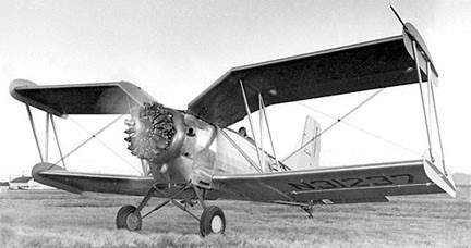
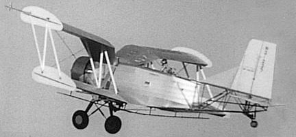
Lamson L.101 Air Tractor

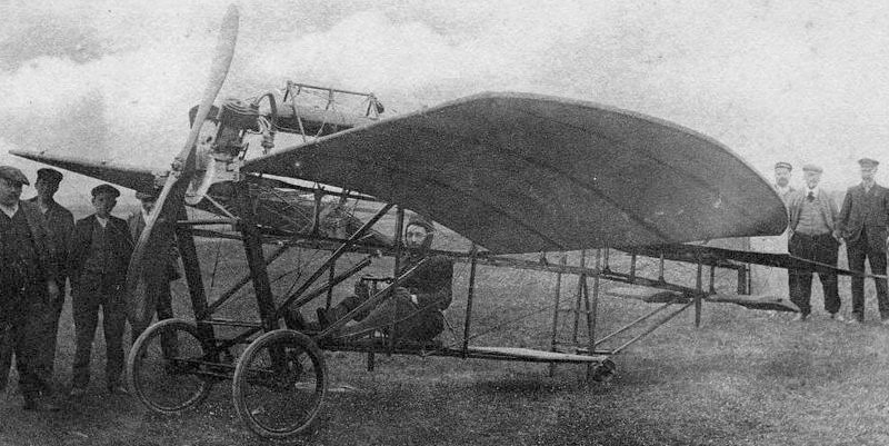
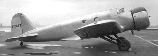
A 1953 agricultural aircraft designed by R T Lamson. Two crop sprayers and seeders with a predominant upper gull-wing were built, registered N31237 and N31238. On the former, wing roots served as fuel tanks, the latter had a metal-covered fuselage with internal fuel tank. Wing units were interchangeable on both prototypes, as were all six tail units.

The first flight was on 10 December 1953, piloted by R T Lamson, a former test pilot for Boeing Co.

Production ceased in 1955.

Engine: P&W R-985, 450 hp
Wing span: 33’7″
Length: 26’5″
Height: 10 ft 8 in
Wing area: 350 sq.ft
Empty weight: 3200 lb
Loaded weight: 5600 lb
Useful load: 2400 lb
Cruise speed: 70-90 mph
Stall speed: 35 mph
ROC: 450 fpm
Hopper load: 360 USgal
Price: c.$15,000 (equipped)
Seats: 1

La Mouette SR

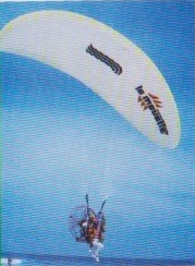
The SR structure can be dismantled for easy transport.

SR 210
Empty weight: 20 kg
Engine: Solo, 12 hp
Reduction: 1:2.5
Prop diameter: 95 cm
Fuel capacity: 6.5 lt
Price (1998): £2800

SR 210 GH
Empty weight: 22 kg
Engine: Solo, 12 hp
Reduction: 1:2.5
Prop diameter: 123 cm
Fuel capacity: 6.5 lt
Price (1998): £3750

SR 250
Empty weight: 29 kg
Engine: Zenoah, 22 hp
Reduction: 1:2.5
Prop diameter: 123 cm
Fuel capacity: 10 lt
Price (1998): £3600

SR 250 Bi
Engine: Zenoah, 22 hp
Reduction: 1:2.5
Prop diameter: 123 cm
Fuel capacity: 10 lt
Price (1998): £3999

Lambert Aircraft Engineering Mission M212

The Mission M212 is a single engine light aircraft of conventional configuration. It has an unswept straight-tapered low wing. The fuselage provides side-by-side seating and has sufficient room to accommodate four adults. In the initial design stages, significant attention was paid to visibility, comfort and ergonomics. The single piece forward hinging canopy provides excellent visibility in level flight as well as in turns. In addition, the clean arrangement ensures a good and water proof seal and keeps aerodynamic noise low. Both the seats and rudder pedals are adjustable. Elevator and aileron control is by sticks. The aircraft is standard equipped with full dual controls.

Control surfaces are conventional with single slotted flaps and an all-moving horizontal tail. The main landing gear consists of a cantilever leaf spring and the steerable nosewheel is of the telescopic oleo-pneumatic type. The airframe is all composite. Construction is mainly of glass fibre and epoxy. Carbon reinforcements are used in spars and longerons where additional stiffness is required.

The development of the Mission M212 started in mid 1992 with a thorough study, which investigated the impact of a light aircraft’s engine on the efficiency of the aircraft as a whole, and which evaluated the potential use of several engines as alternative to the traditional engines.

The project moved to the Cranfield Institute of Technology (now Cranfield University) in October 1992 where the design was started after an extensive market analysis. The specification of the M212-series are mainly based on the results of this market research.

In April 1993 the conceptual design of the Mission was started. A full scale mock-up of the fuselage was built in July 1993 to check for cockpit size, accessibility, visibility and ergonomics. In September 1993 a 1/14 wind tunnel model was built and extensive wind tunnel testing was done during the following months. The conceptual design was completed in January 1994 and the preliminary design in May 1994. Although the Mission was initially not intended for the competition, in the same month, the conceptual design was declared a joint winner in the first stage of the Light Aircraft Design Competition organised by the Royal Aeronautical Society.

The structural design of the Mission was completed by July 1995, after which final drawings were produced. The complete design file of the M212-100, (at that time) the two-seater version, was submitted for the second stage of the Design Competition, and reached a first place.

The construction of tooling was started in January 1996. Fuselage, wing and tailplane plugs were built, of which a set of female moulds were taken. Next, development was concentrated on the wings. All tooling to produce and assemble the components for the wing structure was built.

Concurrently a structural testing programme was set up. Composite materials testing was started early in 1997. Initially work focused on the development and testing of time-saving, reliable and durable manufacturing and assembly methods. Alongside the test work, manufacturing parameters, processes, component lay-up and assembly procedures, quality standards and a quality control system were worked out. In contrast to most proof-of-concept prototypes, the Mission prototype is not a ‘hand carved’ example. Instead all components are produced from production tooling and assembled in the jigs that will be used for series production. In December 1998 a milestone in the development of the Mission was achieved when an assembled wing structure was loaded to the design ultimate load (8.55 g) at 900 kg (2 000 lb), the MAUW (max. all up weight) of the M212-100.

With the prototype wings and control surfaces completed by mid 1999, the work on the fuselage structure was tackled. Again, for all composite parts, moulds were made and an assembly jig for the fuselage was built. The jig ensures correct alignment of the components during assembly. As of July 2001, all structural subassemblies (i.e. wings, fuselage, empennage and control surfaces) were ready for rigging. A jig for matching the wings to the fuselage with the proper incidence and dihedral was built.

While the work on the structure was taking place, the development of the aircraft systems steadily progressed and detail drawings were produced. Subsequently, components for controls and fuel system were manufactured and the subassemblies were ready for installation.

In January 2002, the structural work was finished. With the fuselage standing on the main landing gear, the wings and control surfaces had been rigged and the control systems had been installed. This milestone was celebrated with a roll-out of the Mission M212 prototype on February 8th.

In late February 2002, the firewall forward section was tackled. The engine mount was built. A plug for the cowlings was built, of which female moulds were taken which in turn allowed the cowlings to be made. The prototype was moved to another facility by the end of May for painting. The aircraft was displayed for the first time at the PFA Rally at Cranfield on 21-23 June 2002.

In September and October 2002, structural testing was carried out on the prototype fuselage. Testing was in accordance with FAR-23/JAR-23 airworthiness standards. Stiffness of the structure proved to be very high. Behaviour was entirely to the expectations with no sign of cracks, buckling or wrinkling.

Subsequently the engine was bolted to the engine mount and all accessories onthe engine were installed and connected. Nosewheel steering was also installed. Various improvements were worked out such a redesigned control system for the elevator trim, which meets FAR-23/JAR-23 requirements.

Between December 2002 and June 2003, significant progress was made with installation and completion of various systems and equipment such as cabin heating/ventilation, electrical system, instruments, adjustable front seats and interior. The main landing gear was redesigned to increase its stiffness and raise the maximum landing weight.

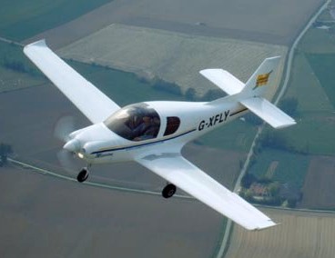
Prototype G-XFLY was on display all day on the Grote Markt (Grand Place) in Kortrijk on 25 June, where it attracted lots of attention of public and press. After returning from the PFA Rally 2003, the aircraft moved to Hangar 63 at Kortrijk-Wevelgem airfield for ground testing and preparations for flight testing. With the aircraft now permanantly assembled, further testing was carried out on control systems. Full ground vibration tests were run in February 2004. The aircraft was inspected several times and subsequent improvements or modifications were designed and integrated. The final version of the design work, the test reports and the JAR-23 compliance list was submitted to PFA Engineering, where a massive effort was undertaken to review drawings and double check all the stressing.
On 23 June, the Mission M212 prototype G-XFLY was given a final inspection. That evening, the inspector, Finbar Colson, signed off all paperwork and declared the aircraft fit for flight. All documents were sent to the PFA headquarters, together with the application for a Permit to Test.

The aircraft was trailered to Cranfield where it was prepared for its maiden flight. The Permit to Test came on 7 July, but bad weather prevented us to fly the aircraft before the PFA Rally two days later.

The first flight was made on Tuesday 13 July 2004 with Roger Bailey, test pilot at Cranfield University, at the controls. The flight lasted 40 minutes and the aircraft behaved very much as expected.

During the following months, the Mission M212 prototype was flown from Cranfield for flight testing. Flight testing was concluded in april 2005 with PFA type approval.

Aircraft performance varies with type of propeller fitted. Engines may be limited to 2500 rpm for optimum noise reduction.

Mission M212
Engine: DeltaHawk DH200A4 XP-360, 147 kW (200 HP) at 2700 rpm
Fuel type: Jet Fuel, Diesel
Wing span: 9.80 m (32 ft 2 in)
Wing area: 12.00 sq.m (129 sq.ft)
Aspect ratio: 7.7
Length: 7.40 m (24 ft 3 in)
Height: 2.90 m (9 ft 6 in)
Tailplane span: 3.20 m (10 ft 6 in)
Wheeltrack: 2.80 m (9 ft 2 in)
Baggage capacity: 200 lt (7 cu ft) approx.
Cabin width: 1.12 m (44 in)
Cabin height: 1.25 m (49 in)
Fuel capacity (std): 160 lt (42 us gal)
Fuel capacity (opt): up to 280 lt (72 us gal)
Never exceed speed: 183 kt (338km/h)
Limit load factors: 3.8/-1.9
Empty weight: 735 kg (1620 lb)
Max. all up weight: 1150 kg (2535 lb)
Max. level speed at S/L: 144 kt (268 km/h)
Max. S/L rate of climb: 1020 ft/min (5.1 m/s)
75% cruise at 8000 ft: 141 kt (261 km/h)
60% cruise at 8000 ft: 130 kt (241 km/h)
Range at 75% (std fuel): 655 nm (1215 km)
Range at 60% (std fuel): 760 nm (1410 km)
Range at 60% (opt. fuel): 1360 nm (2520 km)
Fuel flow at 75%: 32 l/h (8.5 us gal/h)
Fuel flow at 60%: 26 l/h (6.8 us gal/h)
Stall speed, full flaps: 53 kts (98 km/h)
T-O ground roll: 250 m (820 ft)

Mission M212
Engine: Lycoming O-360, 133 kW (180 HP) at 2700 rpm
Fuel type: Avgas 100LL, Unleaded mogas
Wing span: 9.80 m (32 ft 2 in)
Wing area: 12.00 sq.m (129 sq.ft)
Aspect ratio: 7.7
Length: 7.40 m (24 ft 3 in)
Height: 2.90 m (9 ft 6 in)
Tailplane span: 3.20 m (10 ft 6 in)
Wheeltrack: 2.80 m (9 ft 2 in)
Baggage capacity: 200 lt (7 cu ft) approx.
Cabin width: 1.12 m (44 in)
Cabin height: 1.25 m (49 in)
Fuel capacity (std): 160 lt (42 us gal)
Fuel capacity (opt): up to 280 lt (72 us gal)
Never exceed speed: 183 kt (338km/h)
Limit load factors: 3.8/-1.9
Empty weight: 722 kg (1590 lb)
Max. all up weight: 1150 kg (2535 lb)
Max. level speed at S/L: 140 kt (260 km/h)
Max. S/L rate of climb: 900 ft/min (4.5 m/s)
75% cruise at 8000 ft: 137 kt (254 km/h)
60% cruise at 8000 ft: 126 kt (232 km/h)
Range at 75% (std fuel): 480 nm (890 km)
Range at 60% (std fuel): 550 nm (1020 km)
Range at 60% (opt. fuel): 1000 nm (1850 km)
Fuel flow at 75%: 42 l/h (11.0 us gal/h)
Fuel flow at 60%: 34 l/h (8.9 us gal/h)
Stall speed, full flaps: 53 kts (98 km/h)
T-O ground roll: 280 m (920 ft)

Lambert Aircraft Engineering Mission M108

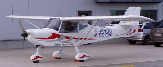
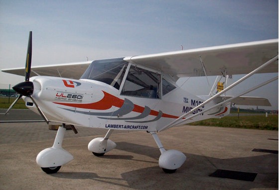
The Mission M108 Light Sport Aircraft is a two seater single engine light sport aircraft. It has an unswept untapered high wing. The fuselage provides comfortable side-by-side seating. Two upwards hinging doors provide access to the cabin. The large transparent areas of the cabin provide excellent visibility in level flight as well as in turns. Both seats are individually adjustable. Elevator and aileron control is by sticks. The aircraft is standard equipped with full dual controls.

The fuselage is a welded space frame, which is fabric covered. High strength steel tubing is used throughout. The wings are of aluminium construction and also fabric covered.
Control surfaces are conventional with single slotted flaps, pushrod operated elevator and cable operated rudder and ailerons. The main landing gear consists of composite cantilever leaf springs. The Mission M108 is available as either a tailwheel or a nosewheel version.

The front mounted ULPower UL260i engine produces 85 HP at 2850 rpm and drives a three blade ground adjustable propeller. The four stroke four cylinder engine is air cooled and features FADEC (Full Authority Digital Engine Control).

With a large choice of options, instruments and avionics, your Mission M108 can be customised to meet your personal preferences.
Depending on the applicable national regulations, the Mission M108 is available as a kit built aircraft or as a ready to fly factory built aircraft.

Mission M108
Engine: ULPower UL260I, 62 kW (85 HP) at 2850 rpm
Wing span: 9.32 m (30 ft 6 in)
Wing area: 11.8 sq.m (127 sq.ft)
Aspect ratio: 7.4
Length: 6.10 m (20 ft)
Height TD: 2.15 m (7 ft 1 in)
Height NW: 1.95 m (6 ft 6 in)
Width wings folded: 2.60 m (8 ft 7 in)
Wheeltrack: 1.75 m (5 ft 10 in)
Max. all up weight: 1320 lbs (600 kg))
Empty weight: 680-700 lbs (310-320 kg)
Fuel capacity: 78 lt standard
Fuel capacity: 110 lt long range
Baggage capacity: 40 kg (90 lbs)
Never exceed speed: 112 kt (210 km/h )
Max. level speed at S/L: 100 kt (185 km/h)
Max. S/L rate of climb: 850 ft/min (4.25 m/s)
Cruise speed: 80-85 kt (150-160 km/h)
Fuel consumption: 12-15 litres/h
Range (20 min res.): 460 nm (850 km)
Stall speed, full flaps: 39 kts (72 km/h)
T-O ground roll: 80-110 m
Max. crosswind TD: 12 kt
Max. crosswind NW: 16 kt
Limit load factors: +3.8/-1.9
Tailplane span: 2.40 m (8 ft 0 in)
Cabin width: 1.08 m (43 in)

Lambert Aircraft Engineering Mission M106

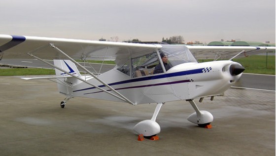
The Mission M106 is a single engine aircraft conventional configuration certified in ULM category in Belgium and France. It has an unswept untapered high wing. The fuselage provides comfortable side-by-side seating. Two upwards hinging doors provide access to the cabin. The large transparent areas of the cabin provide excellent visibility in level flight as well as in turns. Both the seats and rudder pedals are adjustable. Elevator and aileron control is by sticks. The aircraft is standard equipped with full dual controls.
The Mission M106 is available as a factory built Microlight (ULM/UL) category aircraft with tailwheel or nosewheel. It is standard fitted with a UL260i engine and glass cockpit. 2009 Price: 36900 EURO
The fuselage is a welded space frame, which is fabric covered. High strength steel tubing is used throughout. The wings are of aluminium construction and also fabric covered.
Control surfaces are conventional with single slotted flaps, pushrod operated elevator and cable operated rudder and ailerons. The main landing gear consists of composite cantilever leaf springs. The Mission M106 is available as either a tailwheel or a nosewheel version.
The front mounted ULPower UL260i engine produces 82 HP at 2800 rpm and drives a three blade ground adjustable propeller. The four stroke four cylinder engine is air cooled and features FADEC (Full Authority Digital Engine Control).

A ‘glass cockpit’ is standard in the Mission M106. All flight instruments are integrated in the EFIS. Engine instruments are displayed on the EMS. We offer a choice of two instrument panel layouts with displays of different sizes. Optionally, these avionics can be complemented with navigation and communication equipment, such as a GPS with moving map, VHF radio and ATC transponder.

Engine: UL260I, 60 kW (82 hp) at 2800 rpm
Wing span: 9.32 m (30 ft 6 in)
Wing area: 11.8 sq.m (127 sq.ft)
Aspect ratio: 7.4
Length: 6.10 m (20 ft)
Height TD: 2.15 m (7 ft 1 in)
Height NW: 1.95 m (6 ft 6 in)
Width wings folded: 2.60 m (8 ft 7 in)
Empty weight: 260 kg / 573 lb approx.
Max. all up weight: 450 kg / 472.5 kg
Fuel capacity: 78 litres
Baggage capacity: 40 kg (90 lbs)
Max. level speed at S/L: 100 kt (185 km/h)
Never exceed speed: 112 kt (210 km/h )
Cruise speed: 80-85 kt (150-160 km/h)
Fuel consumption: 11-14 litres/h
Range (20 min res.): 380 nm (700 km)
Stall speed, full flaps: 35 kts (65 km/h / 40 mph)
Max. crosswind TD: 12 kt
Max. crosswind NW: 16 kt
Max. S/L rate of climb: 1000 ft/min (5 m/s)
Glide Ratio: 9
T-O ground roll: 80-110 m
Take-off distance (50ft obstacle): 920 ft / 280 m
Landing distance (50ft obstacle): 980 ft / 300 m
Cabin width: 1.08 m (43 in)
Tailplane span: 2.40 m (8 ft 0in)
Wheeltrack: 1.75 m (5 ft 10 in)
Limit load factors: +4.0/-2.0