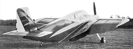
The 1932 LVF (XL-5) open-cockpit mid-wing monoplane NX12865 c/n XL-5 was stable enough not to slip or dive in a stall. In landing it had a tendency to favour a steep descent with control maintained at minimum forward speed.
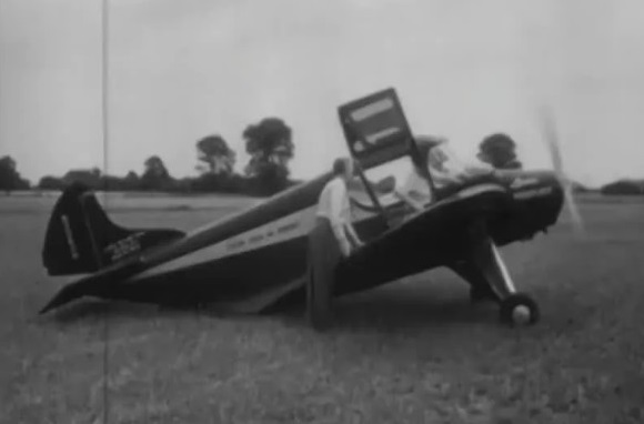
The 1931 XL-4 single-place cabin, high wing monoplane N11512 c/n X-141 was the XL-3 modified with stabilizing wingtip “winglets”. The wing was mounted as a parasol on top of a central pillar which also housed the pilot.
The 1930 XL-2 NX816Y c/n XL-2 had the vacuum cell mounted as a separate box on top of the fuselage. The full-cantilever mid-wing had a span of at least 25′, reportedly a modified Durand 13 airfoil. The tail consiste of twin fins and rudders. The pilot was in an enclosed cabin under the wing.
The 1928 XL-1 N3505 c/n 1 was a single-place, open cockpit low-wing monoplane powered by an Anzani engine. The apprimately 8’10” span wings were spaced away from the fuselage to allow the air to flow against the vacuum cell.
The 1949 443 Paraplane was apparently a larger, possibly high-wing, reconstruction of the Lanier Paraplane with a 180hp Lycoming O-320, again registered N9060H. The project was abandoned circa 1955 after failing to attract a market.
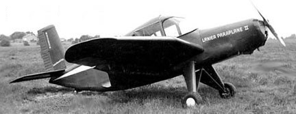
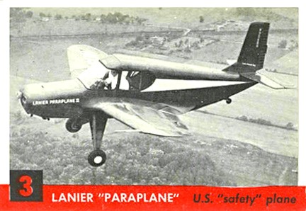
The 1949 120 Paraplane I N9060H test-bed was used by Office of Naval Research in STOL evaluation. First flown by Leo Riley, the Paraplane featured an inverted “Vacucell” gull-wing with an air scoop below and vacuum-slots on top—operated by a hand-crank in the cockpit—enabled slow flight at 19mph, take-off in 100′, a 30° climb angle and 40° descent angle, and was spin- and stall-proof.
A modified Paraplane II showed up in 1949 with a 22’6″ wing and was capable of nearly hovering.
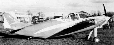
The 1958 110 Paraplane Commuter PL-8 N4157A was built for controllable slow-flight at 20-25 mph and take-off and land in 60 ft. The Paraplane Commuter 110 or 110 Paraplane Commuter PL-8 was one of the last designs stemming from Edward H. Lanier’s 1930s patents, and aircraft incorporating apertures in the upper surfaces, which claimed to give benefits in safety, lift and STOL ability.
In the early 1930s Edward H. Lanier published six US patents concerned with increased aircraft lift and stability, minimising the stall, sideslip and spin. This was to be achieved through vacuum chamber (“Vacua-cells”), initially in the upper fuselage but later in the upper wing, where the reduced pressure established by airflow over a curved surface would act on the lower surface inside the cell, providing lift. The second patent suggests that the cell should contain angled spanwise slats to prevent air entering them at low speeds and that these should be adjustable so that the cells could be closed when required. The earlier patents stress stability improvements; claims of enhanced lift begin with the fourth patent. Five Lanier Vacuaplanes were built in the 1930s, followed by three Paraplanes from about 1948, before the Paraplane Commuter 110 which first flew in 1958.
The Commuter 110 had a wing area of 111 sq ft (10.3 sq.m), large for its 20 ft 7 in (6.28 m) span, and controllable air entrance slots (“Vacua-Jets”) under the lower surface near its leading edge, passing air to the upper surface for boundary layer control. Other details of the upper surface are scarce but photographs appear to show rear hinged, single-piece slats over Vacua-cells as well as narrow open channels next to the fuselage in the very long wing root fairings. Structurally, the cantilever mid wing had strongly cranked inner sections and was tapered in plan with elliptical wing tips. The outer panels carried control surfaces which operated differentially as ailerons and together as flaps. In addition, there were split flaps under the trailing edges of the wing roots.
The fuselage of the Commuter 110 was a semi-monocoque structure, flat-sided and tapering upwards markedly aft of the wing roots to the tail. The pilot sat in an enclosed cockpit long enough to contain a second seat in tandem, the canopy merging into the upper fuselage at its rear. One source describes the Commuter as a single seat aircraft, another as a one or two seater. The Commuter’s empennage was conventional, with straight edged, square-tipped horizontal surfaces and a straight edged rudder with a trim tab mounted on a narrow fin with a fillet to the fuselage. There was a 150 hp (112 kW) Lycoming O-320 air-cooled flat-four engine in the nose, driving a two-blade propeller. It had a fixed conventional undercarriage with cantilever main legs mounted on the lower fuselage and a short-legged tailwheel on the sloping underside, about halfway between the edges of the root fairings and the extreme tail. The mainwheels had brakes and the tailwheel was steerable.
The Commuter made its first flight in 1958. Described as an STOL aircraft, it had respectable takeoff and landing characteristics, though no records comparing performance with open and closed Vacua-cells seems to have survived. A more recent study suggests the known figures were not exceptional given its thick wing, weight and power. Perhaps more significantly, the authors’ computed aerodynamic investigations of open or slatted upper wing surfaces, though made at very low Reynolds numbers, show no evidence that Vacua-cells enhanced wing performance.
The name, Paraplane, fell out of copyright and was adopted for powered parachutes c.2000.
Lanier Paraplane PL-8 N4157A
Lanier Paraplane Commuter 110 Engine: Lycoming O-320, 150hp Propeller: 2-bladed McCauley, 6 ft 4 in (1.93 m) diameter metal, fixed pitch Wingspan: 20’7″ (6.28 m) Wing area: 111.0 sq ft (10.31 m2) Aspect ratio: 3.8 Length: 21’5″ (6.53 m) Empty weight: 780 lb (354 kg) Gross weight: 1,280 lb (581 kg) normal Max takeoff weight: 1,400 lb (635 kg) ferrying Fuel capacity: 24 US gal (20 Imp gal; 91 L) normal, in wing tanks; 44 US gal (37 Imp gal; 166 L) for ferrying Max speed: 165 mph (266 km/h, 143 kn) Cruise speed: 151 mph (243 km/h, 131 kn) Stall: 30 mph Range: 625 mi (1,006 km, 543 nmi) normal, with 45 min res Service ceiling: 23,000 ft (7,000 m) Rate of climb: 1,500 ft/min (7.6 m/s) Take-off and landing speeds: less than 30 mph (48 km/h) Take-off and landing runs: 60 ft (18 m) Seats: 1-2
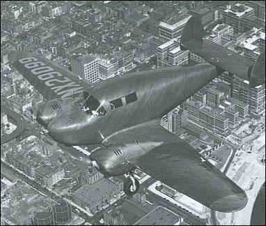
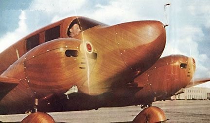
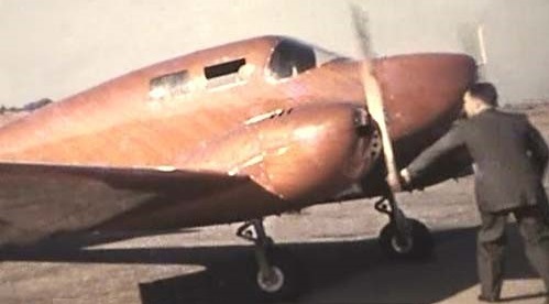
The Langley 2-4, variously described as the Langley Monoplane or Langley Twin was a twin-engine utility aircraft built in the United States and first flown in 1940. Named in honour of Samuel Pierpont Langley, the aircraft was designed by Arthur Draper and Martin Jensen to make use of non-strategic materials in its construction and thereby avoid any shortages brought about by war. Its design was conventional – a low-wing cantilever monoplane with twin tails and tailwheel undercarriage.
The manufacturing process, however, was unorthodox, and the aircraft’s structures were built up from mahogany veneers bent over moulds and impregnated with vinyl and phenol resins to make them hold their shape. The Vidal plastic-bonded mahogany plywood construction. The use of metal for structural elements – even in fasteners – was thereby almost completely avoided.
Two prototypes were constructed, one with 65 hp (49 kW) engines NX29099, and another (29-90 NC/N51706) with 90 hp (67 kW) engines. The second machine was purchased by the United States Navy and evaluated as the XNL-1 39056, but the navy did not order the type. The Langley was a Type Certificated airplane, achieving ATC number 755.
Once the United States entered the war, it transpired that the resins needed for construction were in far shorter supply than the metal that would have been needed to produce an aircraft by conventional means, and the project was abandoned.
The XNL-1 was sold as war surplus. The Langley was landing in Oklahoma in 1965 and after touch down the brakes locked flipping the airplane over and damaging the fuselage beyond economical repair.
John Pierce and Hurley Boehler had a Stinson 108 fuselage in their hangar without wings, so they decided to purchase the Langley and, following the accident, its wings, engine nacelles, and main undercarriage were mated to a Stinson 108 fuselage to create a one-of-a-kind homebuilt aircraft named the Pierce Arrow N6622A.
2-4-65 Engines: 2 × Franklin 4AC, 65 hp (49 kW) Length: 20 ft 8 in (6.30 m) Wingspan: 35 ft 2 in (10.72 m) Maximum take-off weight: 1155 lb Maximum speed: 135 mph (216 km/h) Cruising speed: 185 kph Stall: 50 mph Range: 400 miles (640 km) Service ceiling: 13,300 ft (4,100 m) Take-off distance: 200 ft Crew: one pilot Capacity: three passengers
2-4-90 / NL-1 Engines: 2 × Franklin, 90 hp Wingspan: 35 ft 2 in (10.72 m) Length: 20 ft 8 in (6.30 m) Empty weight: 1738 lb Loaded weight: 2850 lb Maximum speed: 138 mph Cruising speed: 117 kph Stall: 55 mph Range: 350 miles at 100 mph ROC: 695 fpm Crew: one pilot Capacity: three passengers
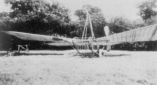
Built in 1908-1909, assembled and tested at Knockholt Cricket ground in Kent, it took off, but crashed on the first attempt and appears not to have been rebuilt. The fuselage was an open parallel girder, with curved top and bottom members meeting at both front and rear ends. Fitted with a tail plane and front elevator, there was considerable dihedral to the wings, which were braced to a tall pylon of four struts, and could be warped. The unidentified type of motor drove twin tractor propellers, apparently by shafts and bevel gearing.