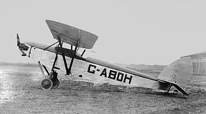
The Royal Aircraft Establishment Aero Club Scarab c/n 5 was designed by P.G.N.Peters and C.R.Brewer in 1930, using some DH.53 parts. A single-seat parasol monoplane, it was powered by a Bristol Cherub III engine and sometimes known as the P. B. Scarab.
Registered G-ABOH, it was finished in 1930 but was rebuilt in 1931 without having flown.
It first flew in 1932 at Farnborough. It was stored there until 1938 when it was broken up.
Engine: Bristol Cherub III Wing span: 30.00 ft Length: 21.00 ft
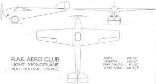
The Royal Aircraft Establishment Aero Club Hurricane c/n 2 was a single-seat, all wood, biplane, with high set wing, designed by S.Childs for the 1923 Lympne Light Aircraft Trials
Powered by a 600cc Douglas motor cycle conversion, it first flew from Farnborough in 1923 as G-EBHS.
It was rebuilt in 1925 with a Bristol Cherub III engine and modified undercarriage.
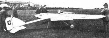
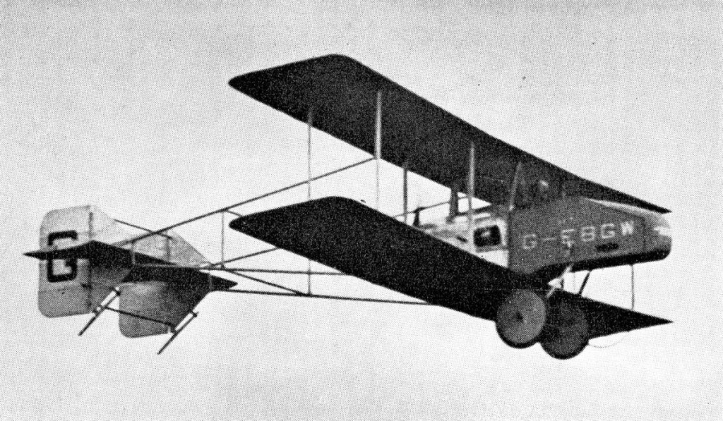
The Royal Aircraft Establishment Aero Club Zephyr c/n 1 was a single-seat, all wood, biplane, powered by a pusher 500cc Douglas motor cycle conversion. The tail was suspended on a twin lattice system from the wing trailing edge.
As G-EBGW, it was first flown at Farnborough on 6 September 1923.
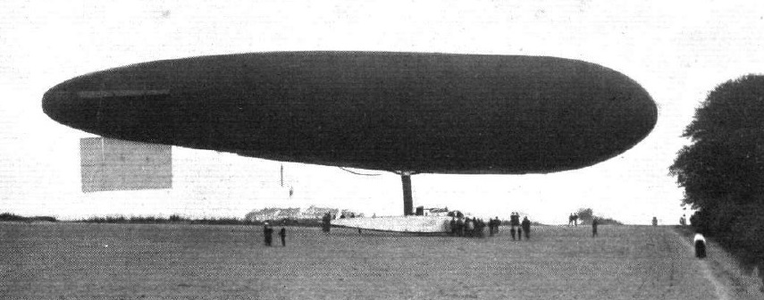
The “Eta” which in a progressive series of small experimental airships built at the Royal Aircraft Factory. The small airships that have been built there were quite inadequate from the standpoint of national requirements.
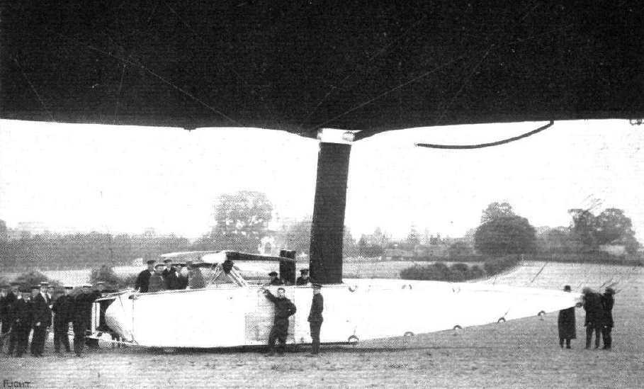
The capacity of the 1913 “Eta” is 100,000 cubic ft, and.it carried 160 hp in two radial stationary Canton-Unne engines, set on opposite sides of the car with their axes placed transversely. Oblique shafts transmit the power to gearing, supported by an overhead framework, which also carries the swivelling propellers. As the airship ascends, these propellers are swivelled round, so that ultimately their axes are horizontal for full speed ahead. In order to stop the airship they can be turned completely round so as to thrust backwards, and they can similarly be used for lowering the airship for the purposes of descent.
Launched in August 1913, the Eta was a non-rigid of 118,000 cu.ft incorporating twin ballonets and capable of 46 mph. The Eta introduced the ‘Eta patch’ in its design as an improved anchorage system for car suspension that greatly reduced drag. The Eta patch allowed the car to be made smaller and attached nearer to the envelope, providing a better streamlined form and reducing drag. The patch consisted of a steel ring through which several layer of overlapping material were rove, forming a fan-shaped patch with the ring positioned at the lower apex. The overlapping layers of fabric were glued and stitched to each other and to the envelope, forming a strong attachment position allowing fr better distribution of load.
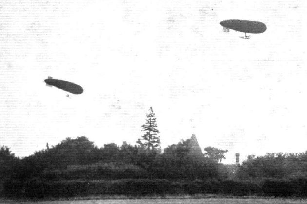
On August 19, 1913, “Naval Airship No.2” (the re-constructed “Willows No.4” – under the command of Lieut. Neville Usborne, R.N.) experienced engine failure due to a broken crankshaft near Odiham in Hampshire. In order to save the hydrogen in the disabled airship, it was decided to try and tow it home employing the airship “Eta” – newly-constructed by the Royal Aircraft Factory and currently undergoing its acceptance trials. Accordingly, a tow-line was attached and the two airships ascended, the “Eta” keeping about 600 feet above the towed ship so as to avoid all chances of fouling the rudder gear. The approximate 8-mile trip back to the airfield at Farnborough was made at a groundspeed of 25 mph against a 5 mph headwind. The “Eta” was in all probability skippered by Army Capt. Waterlow at the time.
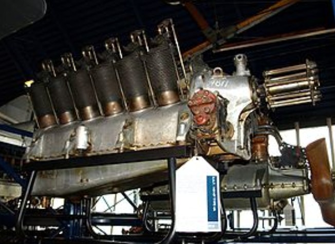
Designed by A.J. Rowledge, the RAF 4 was a British air-cooled, V-12 engine developed for aircraft use during World War I. Based on the eight–cylinder RAF 1 it was designed at the Royal Aircraft Factory, first run in December 1914, but produced by the two British companies of Daimler and Siddeley-Deasy.
More than 3600 were built.
The RAF 5 was a pusher version of the same engine.
In April 1918 a turbocharged experimental version of the RAF 4d was developed using a Rateau turbocharger, the engine being flown in the R.E.8 B738.
The RAF 3 was a British liquid-cooled, V-12 engine developed for aircraft use during World War I. Based on the eight–cylinder RAF 1 it was designed by the Royal Aircraft Factory but produced by the two British companies of Armstrong Whitworth and Napier & Son. First run in September 1914, a total of 289 were built.
The RAF 7 was a high compression version of the same engine.
The RAF 2 was a British air-cooled, nine-cylinder radial engine developed for aircraft use just prior to World War I. It was designed and built by the Royal Aircraft Factory, and first run in October 1913.
Applications: Royal Aircraft Factory B.E.8
Specifications: RAF 2 Type: 9-cylinder, single-row, radial engine Bore: 3.94 in (100 mm) Stroke: 5.51 in (140 mm) Displacement: 604.6 cu in (9.9 L) Valvetrain: Poppet valve Cooling system: Air-cooled Reduction gear: 0.563:1, geared epicyclic, right-hand tractor Power output: 120 hp (90 kW) Specific power: 0.2 hp/cu in (9.2 kW/L)
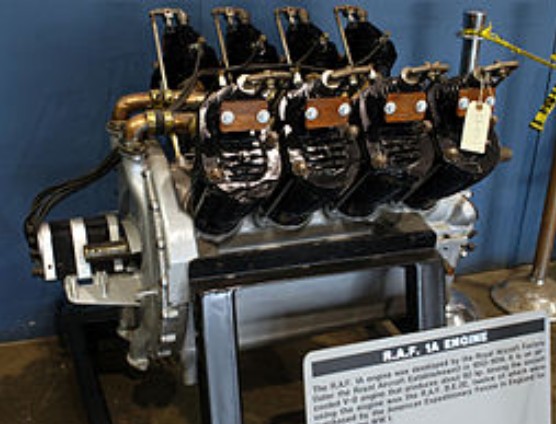
First run in 1913, the RAF 1 was a British air-cooled, V-8 engine developed for aircraft use during World War I. Based on a French design it was designed by the Royal Aircraft Factory but built by six different British companies including Daimler, Rolls-Royce and Wolseley Motors Limited.
The RAF 1 was based on the Renault 70/80 hp engine, being intended specifically to replace that engine in the B.E.2c. It featured larger cylinders (3.9 in × 5.5 in (99 mm × 140 mm)) for a total displacement of 540 cubic inches (8.8 L). It was rated at 92 hp (70 kW) at 1,600 rpm. The heads were cast integrally with the cylinders, with the intake and exhaust valves set one above the other in an upside-down F-head configuration. The engines featured a large diameter lightweight flywheel at the rear, enclosed in a cast housing. Engine oil was picked up from the bottom of the crankcase and slung into a reservoir at the top. From there it was gravity fed, via a gallery high on the right side of the engine block, to the main bearing caps, and then to the connecting rod journals by centrifugal effect of the turning crankshaft. The main bearings were ball bearings and were splash fed. Engine oil from the gallery was also supplied to the 1 : 2 reduction gearbox at the front. This drove the four-bladed propeller at one half engine speed, and the single camshaft was splined into the rear of the short propeller shaft. This arrangement meant that no mechanical oil pump was needed. Excess engine oil from the flywheel overflowed the reservoir and trickled over the large surface area of the round flywheel cover. Two passages cast into the cover took air-fuel mixture from the carby mounted at the bottom to a copper U-shaped inlet manifold mounted between the banks of cylinders, and the flywheel cover acted as a heat exchanger, preheating the fuel-air. In late 1915, the bore was increased to 4.1 inches (100 mm), leading to an increased displacement of 590 cubic inches (9.7 L) and power of 86 kW (115 hp) at 1,800 rpm.
Built under licence by the Lanchester Motor Company Ltd in Birmingham, the RAF 1A is fitted with a Claudel-Hobson carburettor.
In late 1915 a supercharged experimental version of the RAF 1a was developed, the engine being flown in a B.E.2c improving the climb from taking 36 minutes to reach 8,500ft without the supercharger, to reaching 11,500ft in the same time.