Design work on Aircraft 18 was commenced at the beginning of 1939 to meet an official Swedish requirement for a reconnaissance aircraft. The Air Force chiefs had announced a competition for the design of a twin-engined aircraft to replace the old B3. The competition was won by Saab.
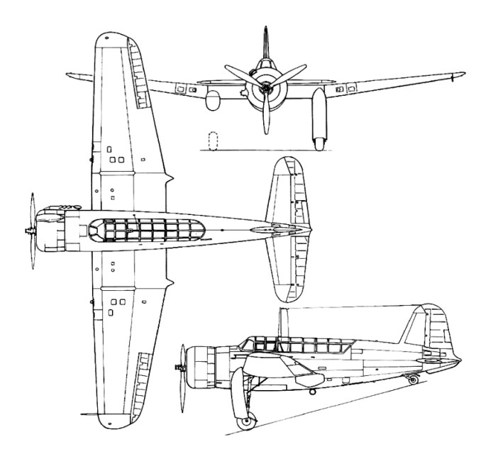
A cantilever mid-wing monoplane, primarily of metal construction, the Saab-18 had retractable tailwheel landing gear, a twin-fin-and-rudder tail unit, and was powered as first flown by two 794kW Swedish-built Pratt & Whitney R-1830 Twin Wasp radial engines in wing-mounted nacelles. The crew comprised a pilot, navigator/gunner and bomb-aimer, the last having a position in the glazed nose of the fuselage.
The first prototype took to the air on 19 June 1942. As a result of changing requirements, the two Saab-18A prototypes were redesigned and equipped for the light bomber or dive-bomber role. Early testing of the prototypes revealed that the Saab-18A was underpowered, but with no immediate remedy available.
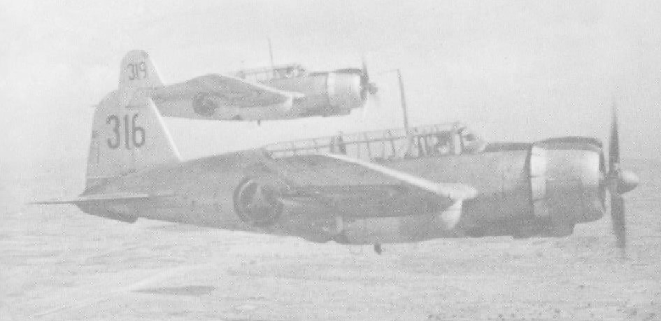
The type was ordered into production in B18A bomber and S18A photo-reconnaissance versions, built to a combined total of 60 aircraft; late production examples of the S18A also carried radar equipment. Delivered to Bomber Wing Fl in June 1944, the aircraft was designated the B18. Several B18s were con-verted for reconnaissance duties with the installation of radar and camera equipment. This version became known as the B18A.
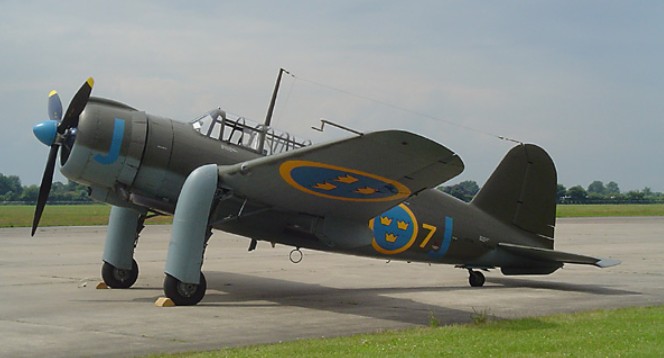
The availability in 1944 of a Swedish licence-built version of the much more powerful Daimler-Benz DB 605B powerplant led to the single Saab-18B prototype, first flown on 10 June 1944 and followed by 120 B18B dive-bomber production aircraft. With new engines, this version was one of the fastest piston-engined aircraft in the world, reaching a top speed of 570 km/h (354 mph).
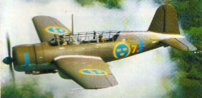
Final production version was the T18B (62 built) which had been developed to serve as a torpedo-bomber but was, instead, completed as an attack aircraft. With a crew of two, this could either be fitted with torpedoes for anti-shipping duties or armed with a single 157-mm and two 20-mm automatic Bofors cannons. Production of the last T18B ended in 1948.
242 production aircraft serviced until the last of them was retired in 1956.
B/S18A Span: 17.04 m (55 ft 10.75 in) Length: 13.23 m (43 ft 4,75 in) Take-off weight: 8700 kg (1918 lb) Maximum speed: 465 kph (289 mph) Cruising speed: 415 kph (258 mph) Landing speed: 135 kph (84 mph) Range: 2200 km (1367 miles) Max. altitude: 8000 m (26250 ft)
B18B Engines: 2 x Daimler-Benz DB 605B, 1100kW Span: 17.04 m (55 ft 10.75 in) Length: 13.23 m (43 ft 4,75 in) Height: 4.35 m / 14 ft 3 in Wing area: 43.75 sq.m / 470.92 sq ft Take-off weight: 8793 kg (1938 lb) Maximum speed: 570 kph (354mph) Cruising speed: 480 kph (298 mph) Landing speed: 125 kph (78 mph) Ceiling: 9800 m / 32150 ft Range: 2600 km (1616 mph) Max. altitude: 9800 m (32150 ft) Armament: 1 x 7.9mm and 2 x 13.2mm machine-guns Bombload: 1500kg
T18B Span: 17.04 m (55 ft 10.75 in) Length: 13.23 m (43 ft 4,75 in) Take-off weight, kg (lb) 9272 kg (2044 lb) Maximum speed: 595 kph (370 mph) Cruising speed: 480 kph (298 mph) Landing speed: 130 kph (81 mph) Range: 2600 km (1616 miles) Max. altitude: 9300 m (30150 ft)
In the late 1930s, ASJA and Saab in Trollhättan (operating under the joint title of AB Förenade Flygverkstäder) competed with each other to build a reconnaissance aircraft for the Swedish Air Force. Although the order went to ASJA, its activities were taken over by Saab in early 1939 and Aircraft 17 became exclusively a Saab project.
Developed in close collaboration with American engineers, the aircraft was a mid¬wing monoplane equipped with retractable landing gear. The SAAB B17 was first designed as a reconnaissance aircraft but was mainly used as a dive-bomber.
Production was under Swedish direction, the Americans being responsible for the drafting work. The first test flight took place on 18 May 1940, six months after the end of the American involvement in the project. Not unexpectedly, teething troubles were encountered – the cockpit canopy blew off, spin was difficult to correct and the engine stalled in a right-hand spin. However, when the Air Force came to test the plane, they found that “the aircraft and its equipment are of a generally excellent standard”.
Following the first flight the company made the proposal that its development as a bomber should be given consideration by the Flygvapen. Evaluation of the prototype led to the aircraft being developed for this role as well as for reconnaissance.
B17
In 1940, the Swedish Air Force ordered 322 aircraft that were delivered in the period December 1941 – 1944.
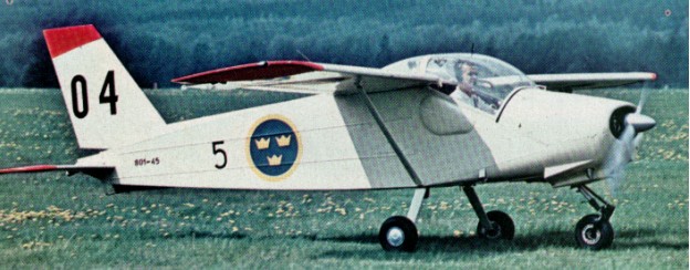
Five versions were developed out of the basic SAAB B17. A cantilever mid-wing monoplane with retractable tail-wheel landing gear, the Saab-17 had its crew accommodated beneath a long continuous canopy. Powerplant varied, the B17A dive-bomber having the 794kW / 1065 hp Svenska Flygmotor-built Pratt & Whitney R-1830-SC3G Twin Wasp radial. A light bomber, the B 17A armament consisted of two fixed 8 mm machine-guns m/22 in the wings and a moveable 8 mm machine-gun at the observers place behind the pilot. A bomb-load of 500 kg could be carried. 132 SAAB B 17A were manufactured.
The B17B dive-bomber and similar S17B (equipped for the reconnaissance role) powered by the 731kW Swedish-built Bristol Pegasus XXIV radial, and the B17C dive-bomber (which differed from the B17B only in its engine, the Piaggio P.XIbis). Included in the total production were 38 examples of the S17BS, a maritime patrol version of the B17B on twin floats. Many of the landplane versions were later given retractable ski landing gear for operation from snow-covered surfaces.
325 were built.
Entering service with the Flygvapen in 1941, the Saab-17 was notable for the robust construction that has since been a feature of the company’s designs, and the type remained in service until 1948. Although retired from active operation in 1948, the Saab 17 continued to fly as a target towplane until 1968.
After World War II 47 were delivered to the Ethiopian air force.
17A Engine: STWC 3 Pratt & Whitney Twin Wasp/ 1065 hp Span: 13.7 m (45 ft 1 in) Length: 9.8 m (35 ft 1.75 in) Height: 14 ft 6 in Wing area: 307 sq.ft Take-off weight: 3790 kg (8355 lb) Maximum speed: 435 kph (270 mph) Cruising speed: 390 kph (242 mph) Landing speed: 125 kph (77 mph) Range: 1800 km (1120 miles) Max altitude: 8700 m (28550 ft)
17B Engine: Bristol Mercury XXI V/980 hp Span: 13.7 m (44 ft 11.25 in) Length: 9.8 m (35 ft 1.75 in) Take-off weight: 3605 kg (7948 lb) Maximum speed: 395 kph (245 mph) Cruising speed: 375 kph (233 mph) Landing speed: 125 kph (77 mph) Range: 1400 km (870 miles) Max. altitude: 8000 m (26250 ft)
17BS Engine: Bristol Mercury XXI V/980 hp Span: 13.7 m (44 ft 11.25 in) Length: 9.8 m (35 ft 1.75 in) Take-off weight: 3825 kg (8433 lb) Maximum speed: 330 kph (205 mph) Cruising speed: 315 kph (196 mph) Landing speed: 125 kph (77 mph) Range: 2000 km (1240 miles) Max. altitude: 6800 m (22300 ft)
17C Engine: Piaggio PXI bis RC40D, 1040 hp / 761kW Span: 13.7 m (44 ft 11.25 in) Length: 9.8 m (35 ft 1.75 in) Height: 4.40 m / 14 ft 5 in Wing area: 28.50 sq.m / 306.77 sq ft Take-off weight: 3870 kg (8532 lb) Maximum speed: 435 kph (270 mph) Cruising speed: 370 kph (230 mph) Landing speed: 125 kph (77 mph) Range: 1700 km (1060 miles) Max. altitude: 9800 m (32150 ft) Armament: 2 x 13.2mm + 1 x 7.9mm machine-guns Bomb load: 680kg
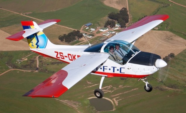
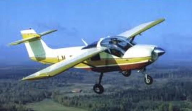
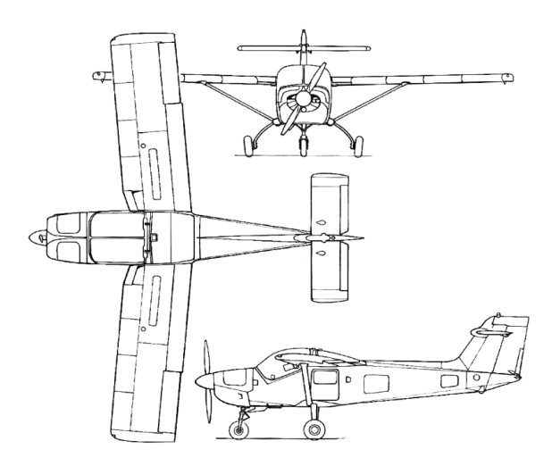
MFI had then been de¬veloping the MFI¬ 15A when Saab acquired Malmö Flygindustri (MFI) in 1968. The airplane made its maiden flight on 11 July 1969. As then flown it was powered by a 119kW Avco Lycoming IO-320-B2 flat-four engine and had a conventional low-set tailplane, but this was modified subsequently to T-tail configuration to minimise damage when operating from rough airfields. Later renamed Safari and then further developed into MFI-17 Supporter armed ground-support version. The plane was converted into an efficient weapons carrier by increasing the engine power and making some structural modifica¬tions – measures which greatly enhanced its military potential. The new version – the MFI-17 – made its first flight on 6 July 1972.
The prototype was flown on 26 February 1971 with a more powerful Avco Lycoming engine, which became the standard powerplant for the production version, which was re-designated Saab Safari. A braced shoulder-wing monoplane with fixed tricycle landing gear, available optionally with tailwheel landing gear, it provides side-by-side enclosed accommodation for two and has dual controls as standard.
A military version designated originally Saab-MFI 17 was flown on 6 July 1972 and differed from the Safari by being equipped more specifically for use as a military trainer, or for such duties as artillery observation, forward air control and liaison; this version was later named Saab Supporter.
The first purely military version, named the Supporter, was sold to Pakistan (where it was built under license as the Mushshak) in 1974. Further sales to Denmark, Norway and Zambia followed. A civilian version named the Safari was also sold to countries including Norway, Sierra Leone and Ethiopia. Counting both versions, more than 200 of the aircraft were built.
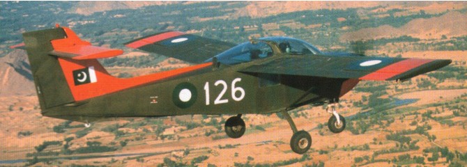
Pakistan Aeronautical Complex Super Mushshak
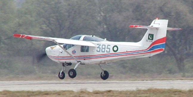
Licence production of the Saab MFI-17 Supporter two/three-seat piston-engined trainer and liaison aircraft continued at Kamra for the Pakistan Air Force and Army in 1987 by the Pakistan Aeronautical Complex, as the Mushshak.
Two MFI-17Bs were shipped to the PAF Academy in September 1974 for evaluation by trainer pilots and the Pakistan Army signed a contract with Saab in June 1974 to acquire five MFI-17B Supporters along with supply kits. The contract was signed to supercede the obsolete Howard L-19 trainer aircraft. A licence agreement was also obtained to build an indigenous aircraft based on the MFI-17B.
Assembly of Swedish-made kits began in 1976, but complete aircraft are manufactured in Pakistan using imported raw materials, engines, propellers, and avionics equipment. Licence-production of this aircraft was started in Pakistan during 1976, initially from kits supplied by Saab, but there has been a gradual change to indigenous manufacture from raw materials. Designated Mushshak in Pakistan, more than 150 have been built.
Upon taking the required suggestions from the Academy, the PAC started the development of MFI-17 Mushshak in June 1975 at its facility in Kamra, Pakistan. Saab ceased the supporter aircraft parts supply in 1982. The maiden MFI-17 Mushshak production aircraft was introduced in December 1983. The aircraft has been accredited by the Pakistan Civil Aviation Authority, and has obtained Type Acceptance certification from the South African Civil Aviation Authority.
The MFI-17 features two integral fuel tanks that carry 48gal of fuel. It also houses an electrical fuel pump for emergency missions. The aircraft is fitted with a Bendix fuel injection system, dual flight control systems, tricycle type landing gear, electrical trim, rudder pedals, ailerons and environmental control system.
It boasts a large luggage compartment on the rear side of the cockpit, which can be easily accessed through a door on the port side of the fuselage.
The glass cockpit of the Mushshak accommodates two crew members, a student pilot and an instructor. It is fitted with two adjustable seats integrated with lockable inertia reels, and there is an option for a third seat on the rear side. The round glass canopy offers clear visibility to the crew. An Enviro R-134 air conditioning system maintains constant temperature in the cockpit.
The cockpit is equipped with UHF radios, GPS, a voice-over recorder, automatic direction finder, rate of climb indicator, attitude heading reference system and an information friend or foe transponder.
The aircraft comprises six hardpoints. It is armed with two 7.62mm cannons, two 75mm unguided rocket pods, four 68mm unguided rocket pods and six anti-tank missiles.
The Mushshak is powered by an AEIO-360A1B6 horizontally opposed four-cylinder piston aircraft engine, which generates 149kW of output power. The engine is designed and manufactured by Textron Lycoming. It is a fuel injected engine driven by two bladed constant speed hartzell propeller made up of aluminium.
The time between overhauls of the engine is 2,000 hours.
Orders of the MFI-17 include: the Egyptian Air Force (54), the Islamic Republic of Iran Air Force (25), the Royal Air Force of Oman (Eight), the Pakistan Air Force (149), the Royal Saudi Air Force (20) and the Syrian Air Force (Six).
The Danish airforce chose in 1974 Saab Supporter as their new trainer.
The MFI-17 was designed to train pilots of the PAF Academy located at Risalpur. The aircraft is fitted with a blind flying screen allowing for instrument flying missions. It was designed to meet the US FAR23 certification standards in utility and aerobatics classes.
The Mushshak was designed to operate on rough airfields even in adverse weather conditions. It can execute a wide range of ground attack missions including forward air control, border patrol, reconnaissance, artillery fire observation, liaison, camouflage review and transportation.
Some Mushshaks, promoted as very light strike and weapons training aircraft, served with the Iranian Revolutionary Guards.
Most of the Pakistan Aeronautical Complex Mushshak were upgraded to the more powerful Super Mushshak with a Lycoming 260 hp engine.
Variants: Pakistan Aeronautical Complex MFI-395 Super Mushshak
Saab-Safari Engine: 1 x Avco Lycoming IO-360-A1B6, 149kW / 200 hp Max take-off weight: 1200 kg / 2646 lb Loaded weight: 646 kg / 1424 lb Wingspan: 8.85 m / 29 ft 0 in Length: 7.0 m / 22 ft 11 in Height: 2.6 m / 9 ft 6 in Wing area: 11.9 sq.m / 128.09 sq ft Max. speed: 235 km/h / 146 mph Cruising speed: 208 km/h (129 mph) Landing speed: 90 km/h (56 mph) Range: 1050 km (650 miles) Ceiling: 4100 m / 13450 ft
Pakistan Aeronautical Complex MFI-17 Mushshak Engine: Textron Lycoming AEIO-360A1B6, 149kW Propeller: two bladed constant speed hartzell Climb rate: 5.2m/s Maximum speed: 238km/h Cruise speed: 210km/h Stall speed: 100km/h Range: 800km Service ceiling: 4,100m Endurance: 5 hr 10 min
1929 prototype Armstrong Siddeley Jaguar, 425 hp 1 to Swedish Air force as J5, 1 to Norway Re-engined Bristol Jupiter VI as J6A Bristol Jupiter VII as J6B
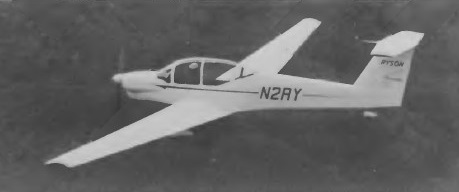
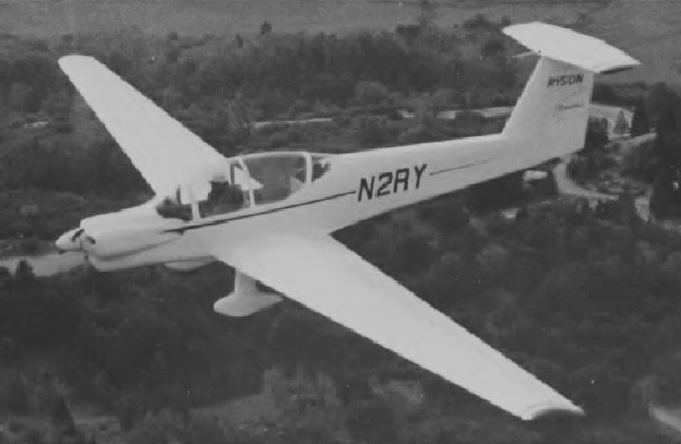
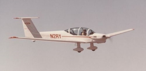
The ST-100 Cloudster tandem two-seater motor glider is believed to be the first American type in this category to be designed for production, and was created by the Ryson Aviation Corporation. A Pazmany designed self launching sailplane called the Cloudster, in mem¬ory of the original flagship of Ryan Airlines. The work Pazmany did designing the Cloudster’s landing gear led him to write the book “Landing Gear Design For Light Aircraft”.
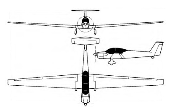
Design work started on 18 March 1974 as a cantilever low-wing monoplane of all-metal construction, with a T-tail, a fixed spatted undercarriage and a conventional engine installation with a Continental O-200, and of all-metal construction. The wings are all-metal safe-life structures, with some fail-safe features, and have a single main spar located at the 40% chord line, the point of maximum thickness, and an auxiliary spar at 80% chord; dihedral is 4°. Both ailerons and trailing edge flaps are of aluminium with a foam core, the flaps being electrically-operated and can be lowered to 72° when used as air brakes; the ailerons, like the flaps, can be raised 12° and they can be drooped 8° in conjunction with the flaps. After that, the flaps continue down to any desired position. No spoilers or trim tabs are fitted, and the wings can be folded back alongside the fuselage, leading edges down, for hangarage or transportation. The fuselage is a semi-monocoque structure with extruded aluminium longerons, and sheet metal frames, bulkheads and skinning. The pilots sit in tandem under a one-piece Plexiglas canopy that opens sideways to starboard; there is baggage space aft of the rear seat, and the rear occupant has flight controls but not an instrument panel, as he can see the instruments over the front pilot’s shoulders. Both seats are designed to accommodate parachutes, and the cockpit is heated and ventilated. The cantilever T-tail has a sweptback fin and rudder, a fixed-incidence tailplane and a one-piece balanced elevator. The rudder and elevator are aluminium-covered, with sheet metal and foam ribs, and the elevator tips can be removed when the aircraft is being transported; the elevator has an anti-servo and trim tab. A conventional fixed tailwheel landing gear is featured, with streamlined glassfibre fairings on the main gear legs, main wheels and tailwheel, which is steerable. The main wheels have Cleveland hydraulic disc brakes and Ryson oleo-pneumatic shock absorbers. Powerplant is a 100hp Continental 0-200-A ‘flat four’ engine driving a two-blade three-position Hoffman HO-V-62 feathering propeller with composite blades. There are two integral fuel tanks in the wing centre section leading edges with a total capacity of 32 US gallons (26.6 Imp gallons.)
Construction of the prototype, registered N2RY, began on 11 July 1974; it made its first flight on 21 December 1976 in the hands of test pilot Ray Cote.
The ST-100 is designed to be aerobatic and to meet the FAR Part 23 gust load requirements. It can also be used as an aero-tow aircraft for unpowered sailplanes. It has towed a Schweizer SGS 1-26 single-seater to 13,000ft with an initial climb rate of 450ft/min and, with two people aboard, it has also towed a Schweizer SGS 2-33 with two occupants at an initial rate of climb of about 400ft/min.
In the summer of 1977 Ray Cote made a notable economy-record flight in the ST-100 from El Mirage, California, to the EAA display at Oshkosh, Wisconsin, covering the 1,676 miles on 28 of the 32 available US gallons of fuel in 18 hours of soaring flight and 13 hours of powered flight. This was followed by a 4,300 mile flight around the perimeter of the United States. Only 20-percent power is required to keep the Cloudster in level flight. As a touring airplane, it cruises at 135 mph (75-percent power) using just 6 gph to yield a range of 690 miles. At lower power settings, the range can be greatly increased.
Production of the ST-100 by a licensee was planned when FAA type certification was awarded.
Engine: Continental O-200, 74.5 kW / 100 hp Span: 57 ft 8 in / 17.58 m Length: 25 ft 6.5 in / 7.78 m Height: 5 ft 10 in / 1.78 m Wingarea: 213.0 sq.ft / 19.79 sq.m Aspect ratio: 15.61 Airfoil: Wortmann FX 67-170/17 Empty weight: 1,212 lb / 550 kg Max weight: 1,650 lb / 748 kg Water ballast: None Max wing loading 7.74 lb/sq ft / 37.8 kg/sq.m Max speed at sea level: 150 mph / 130 kt / 241 km/h Max cruising speed: 135 mph Stalling speed 69 km/h / 37 kt Min sinking speed: 2.93 ft/sec / 0.89 m/sec Best glide ratio: 28:1 T-O run: 570ft / 174m Take-off run to 50ft: 950 ft Max rate of climb at S/L: 895 fpm / 273 m/min Range 595 nm / 1,103 km Range with max fuel: 900 miles
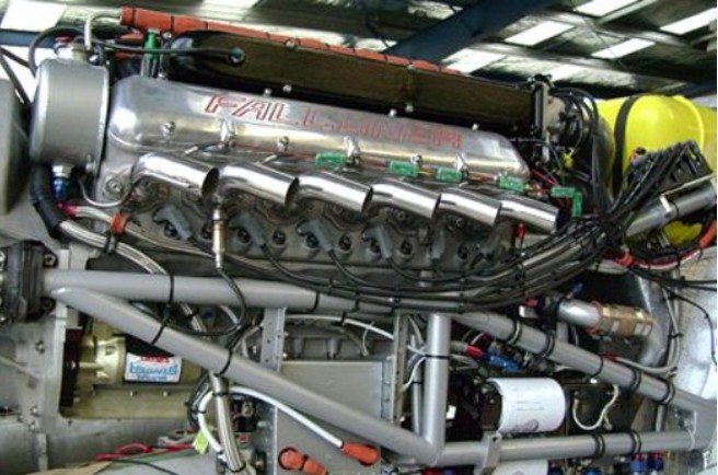
The V-12 engine developed by RFI has been used in racing boats, specialty race and street cars, trucks, airboats and now aircraft. This engine incorporates the latest splayed-valve cylinder head technology and the highest quality internal components developed for acing such as Carrillo rods and JE hypereutectic pistons. The engine was developed by RFI specifically for Papa 51 Ltd. Co. with unique features, including: Special long-runner electronic sequential tuned-port injection system with end-entry plenums for narrow width 10.9:1 compression ratio Special grind hydraulic roller cam for low RPM horsepower and torque Additional bosses on the drive end of the crankcase to provide greater clamp area for the gearbox.
B.J Schramm headed the project to develop the gearbox for Papa 51. Final design and analysis was done by Oswald Webb of England, who worked on the original Merlin engine reduction and was Chief Design Engineer for GKN, the largest gear works in Europe. The unit is designed to endure up to 1500 HP, pulling 13.5 Gs doing 1 second snap rolls for more than 400 hours. The reduction ratio is 2.8:1. It is a straight cut spur gear arrangement with a quill shaft between crankshaft and drive gear.
Ryan Falconer V-12 Type: Aluminum 90 degree V-12 Displacement: 601 cubic inches Horsepower: 640 HP @ 4500 RPM Torque: 700+ ft./lb. @ 4000 RPM Compression Ratio: 10.9:1 Bore: 4.125 in. Stroke: 3.750 in. Fuel: 100 LL Avgas. Heads: Cast aluminum with splayed valve design Cylinders: Steel sleeveds Empty Weight: 2200 lbs Main bearing size: Same as 400 CID Chevrolet “small block” Rod bearing size: Same as 350 CID Chevrolet “small block” Cam bearings: Similar to Chevrolet “small block” Rods: Forged, Carrillo Industriess Pistons: Forged aluminum Valve train: Dual spring Valves: Stainless, 2.190 intake / 1.610 exhaust Rocker assembly: Investment cast stainless steel, 17-4 Roller tappets: AC Delco Pushrods: Smith Brothers Manifold: RFI, with end entry plenums and 70mm butterflies Ignition: Delco Direct Fire (no distributor) with dual MOTEC computers Freeze plugs: Threaded with o-rings Port runners: Pre-machined for better flow Crankshaft: Bryant Timing gears: RFI custom Head gasket: Special, Fel-Pro Dry oil sump pump: RFI custom Damper: Fluidampr Length: 55.5 in. Width: 24.25 in. Weight: 980 lb. (firewall forward, includes: accessories, batteries, gear reduction unit, hoses, propeller, etc.)
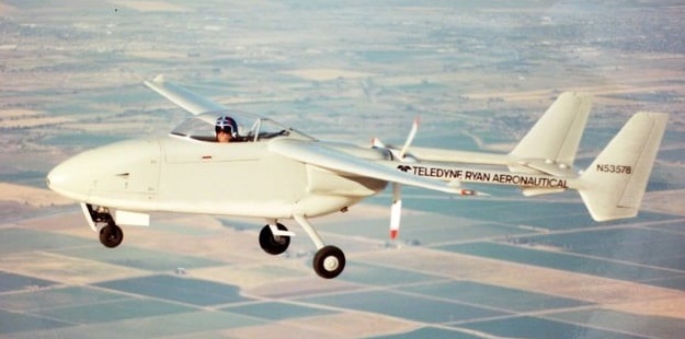
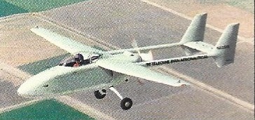
The Teledyne Ryan Model 410 was a surveillance UAV designed in the United States in the late 1980s. In configuration, it was a high-wing cantilever monoplane with twin tails carried on booms and linked by a common horizontal stabilizer. The engine was mounted pusher-fashion at the rear of the fuselage, between the booms. The nosewheel of the tricycle undercarriage was retractable. Construction throughout was of composite materials.
The Model 410 was Ladislao Pazmany’s last design before he quit Ryan. First flying on 27 May 1988, the sole prototype entered its flight test phase at Holtville, Calif, in October 1987. It was converted to manned operation for safety reasons, and completed its manned flight tests early in June 1988. It retained this configuration for the whole of the testing and development phase.
In 1993, the Model 410 was submitted to the UAV Joint Projects Office in response to an RFP for a Tier II system. In January 1994, the contract was awarded to General Atomics for what would eventually become the RQ-1 Predator.
Nothing is known about its fate or current whereabouts of the sole prototype, N53578, but it was deregistered. According to a Northrop Grumman employee, the Model 410 eventually proved overweight.
Powerplant: 1 × Lycoming TIO-320-C1B , 160 hp (120 kW) Wingspan: 31 ft 0 in (9.45 m) Empty weight: 1,450 lb (657.7 kg) Capacity: 300 lb (140 kg) sensor payload carried in internal bay Range: 1,200 mi (1,931.2 km, 1,000 nmi) Endurance: 16 hours
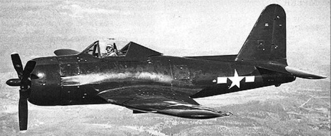
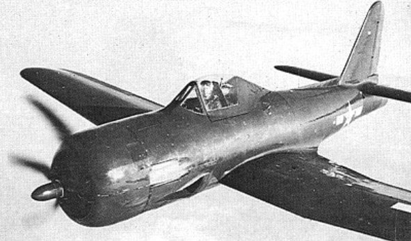
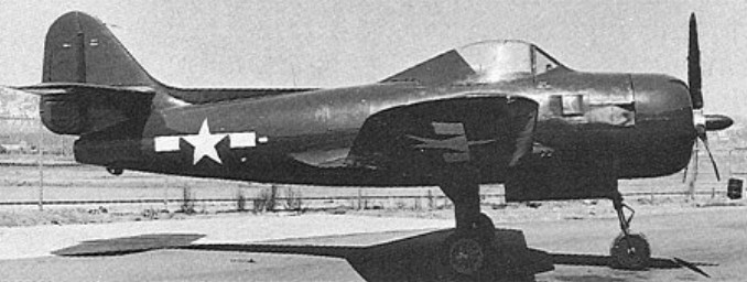
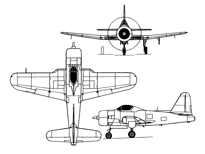
In December 1942, nine US aircraft manufacturers received a Request for Proposals from the Bureau of Aeronautics for a single-seat shipboard fighter combining piston engine and turbojet, the former to be the main power source and the latter to provide boost in climb and combat. The Ryan Model 28, designed by Benjamin T Salmon and William T Immenschuh, was selected as winning contender by the Bureau and three prototypes were ordered on 11 February 1943 as XFR-1s.
A low-wing, cantilever monoplane of classic design, the XFR-1 was the first carrier aircraft designed from the outset to use a laminar-flow aerofoil and the first US Navy aircraft to have an entirely flush-riveted exterior and metal-skinned movable control surfaces. Power was provided by a 1,350hp Wright R-1820-72W Cyclone nine-cylinder air-cooled radial and, in the rear fuselage, a 726kg General Electric I-16 (later redesignated J31) turbojet. Proposed armament consisted of four 12.7mm machine guns with provision for a 454kg bomb under port inboard wing panel. Other features were hydraulically-folding outer wings and a tricycle undercarriage.
A contract for 100 production FR-1s was placed on 2 December 1943, the first XFR-1 flying seven months later, on 25 June 1944, with only the piston engine installed. The turbojet was added a few days later. Initial flight tests led to the major redesign and enlargement of the vertical tail and lowering of the horizontal tail. On 31 January 1945, by which time a number of series FR-1s had been completed and were under test, a contract was placed for 600 FR-2s which were to differ in having the R-1820- 74W engine of 1,500hp with water injection. In the event, neither the FR-2 nor the XFR-3 was to be built, the latter being intended to mate the 907kg General Electric I-20 turbojet with the -74W piston engine.
XFR-4
The XFR-4 entered flight test in November 1944. Utilising the 19th FR-1 production airframe, this replaced the J31-GE-3 turbojet with a 1542kg Westinghouse J34-WE-22, discarded the wing root intakes of the FR-1 in favour of flush inlets in the sides of the forward fuselage, and had the aft fuselage extended by 20cm. It was found, however, that the thrust of the J34 was too great to permit efficient use of both engines and the XFR-4 programme was discontinued accordingly.
Due to its (relatively) high-speed dash capability, the Fireball was considered for use in defence against kamikaze attacks. The war ended just as the first squadron was becoming operational. .Deliveries of the FR-1 to the US Navy began in March 1945, the Fireballs equipping one squadron (VF-66) and completing carrier qualification in May (aboard the USS Ranger). After VJ-Day, the 34 FR-1s remaining to be delivered were cancelled, together with all 600 FR-2s. On 18 October 1945, VF-66 was de-commissioned and its FR-1s transferred to VF-41 (redesignated VF-1E on 15 November 1946) which continued to fly them until mid- July 1947. Only 17 of the 66 FR-1s built saw squadron usage, the remainder being assigned for various test programmes.
FR-1 Engines: 1 x GE J31-GE-3 turbojet, 1600 lbs (726 kg) thrust & 1 x Wright Cyclone R1820-72W, 1425 hp piston. Wingspan: 12.19 m / 40 ft 0 in Length: 9.85 m / 32 ft 4 in Height: 4.24 m / 14 ft 11 in Wing area: 25.54 sq.m / 274.91 sq ft Max take-off weight: 5285 kg / 11651 lb Empty weight: 3488 kg / 7690 lb Max speed: 370 kts, (piston power only: 255 kts). Range: 1658 km / 1030 miles