Adams-Farwell Rotary

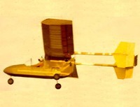
Like another builder of rotary engined road vehicles, Stephen Marius Balzer of New York, the Adams Company offered light gyrocopter engines which successfully powered experimental flying machines by Emile Berliner in 1909-1910 and J. Newton Williams in 1909. A modified 1907 Adams-Farwell engine powered three man-lifting experimental helicopters designed by Emile Berliner.

Cylinders: 5
Cooling: air
Capacity: 621 cu.in
Output: 63 hp
Dry weight: 250 lb

Adams-Farwell

Adams-(F O) Farwell Co
21 Athol St
Dubuque IA
USA

The Roberts & Langworthy Iron Works, located at 57 South Main Street in Dubuque, were manufacturers of “fine light castings” like grave crosses and park benches. Eugene Adams invested in the company in June, 1883 when Roberts decided to retire, and Adams took the position of a secretary and manager. A change of the company name to Langworthy and Adams Iron Works followed in 1885. When Langworthy retired in 1892, Eugene’s brother Herbert bought his share and the company was re-organized as The Adams Company, foundry and machine shop. The plant burnt down the same year in a disastrous fire, and the company opened new facilities at East Fourth Street. Now, machine castings and household devices like a patented floor heating vent with inner rotating portion that distributed warm air in upper level rooms, or laundry stoves were added. In 1895, Fay Oliver Farwell (1859-1935) became manager of the company.

Also about 1895, Farwell begann experimenting with an internal combustion engined automobile, for which he conceived a horizontally mounted rotary engine with three cylinders. The vertically standing crank shaft was fixed in the chassis. Farwell felt this configuration was lighter than conventional engines as it used neither a flywheel nor radiator. He completed the first prototype in 1898. Basically a horse drawn carriage, he mounted his engine between the front wheels.

Like another builder of rotary engined road vehicles, Stephen Marius Balzer of New York, the Adams Company offered light gyrocopter engines which successfully powered experimental flying machines by Emile Berliner in 1909-1910 and J. Newton Williams in 1909. A modified 1907 Adams-Farwell engine powered three man-lifting experimental helicopters designed by Emile Berliner.

Engine production lasted longer than automobile manufacture although it is not clear when this stopped, too. The Adams Company then relied on their iron foundry and manufacture of gears, shafts and parts for power transmissions which it does until today.

When F. Oliver Farwell left the company in 1921, he had about 20 patents on his name and tried to build up a business on one he held for a novel transmission for merry-go-rounds. Later, he worked again in a gear-cutting company in Toledo, Ohio.

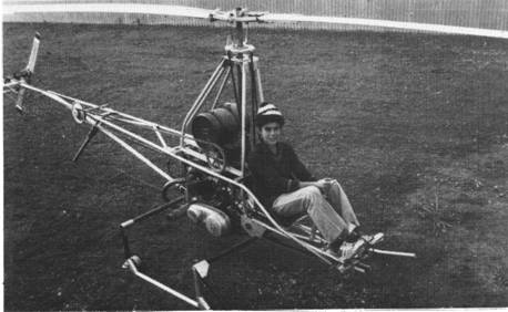
Adams-Wilson Model 101 Hobbycopter / Model 102 Hobbycopter / XH-1 Hobbycopter

This company was formed by Mr. T.G.Adams and Mr. Paul Wilson to market plans the single-seat helicopter named the HobbyCopter, of which they have built a prototype, N23P, with a 34 hp engine.
The company also supplies kits of parts for the Hobby-Copter sold as a kit to amateurs as the Model 101 Hobbycopter, offered in kit (US$900) or plan (US$35) The subsequent Model 102 had a strengthened structure, 50hp Triumph engine and fibreglass cockpit shell.
First flown in November 1958, this single seat fully fledged helicopter was powered by a motor cycle engine, rubber mounted and fitting into the frame with no modifications – including starting procedures.
Powered by a 40-46hp Triumph 650cc motorcycle engine, the engine, as in its original mount, is kick-started. Fuel is in a single tank above engine with a capacity of 11.4 litres. Oil capacity is 3.8 litres.
When the run-up is complete and ready for takeoff, the pilot engages gear through the motorcycle gearbox — the power being transmitted through a one-way drive to the main rotors and by a vee-belt to the tail rotor.
An open air machine, the helicopter utilises skids and features a 22 foot laminated spruce wooden main rotor of NACA 0012 aerofoil section (chord 0.20m) and a formed aluminium two ¬bladed tail rotor.
Cyclic and collective pitch are controlled by a swash-plate.
The rotor drive involves engine-to-gearbox by chain; gearbox-to-main rotor by direct shaft; gearbox-to-tail rotor by belt. The main rotor rpm in flight is 360, and tail rotor rpm in flight 1,800.
The fuselage is all aluminium tube structure, bolted together, with tubular skids, with retractable ground-handling wheels. A single fiberglass bucket seat is ahead of the rotor drive shaft.
The plans are all to aircraft specifications and the structure is bolted together. The main lift bearing is designed to take six tons.

XH-1 HobbyCopter
Engine: 850cc Norton
Main rotor dia: 22 ft / 6.55m
Tail rotor dia: 0.94 m
Fuselage length: 4.27 m
Width: 1.52m
Height: 1.83m
Empty wt: 335 lb
MAUW: 600 lb / 252kg
Weight empty, equipped: 161kg
Max speed: 72 mph / 96km/h
Max cruise: 72km/h
Econ cruising speed: 64km/h
Service ceiling: 2440m
Max range: 193km
Fuel burn: 1.5 USG/hr
Seats: 1

Adamoli-Cattani Fighter

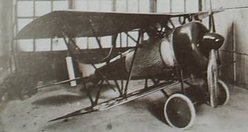
In 1918, Adamoli and Cattani designed the smallest possible single-engine seat fighter around the most powerful rotary engine available, the 200-hp (149-kW) Le Rhone. With conventional wooden construction and fabric covering, the fighter was unequal-span unstaggered biplane with Warren truss-type interplane bracing. Lateral control was by interlinked and hinged wing leading edges varing the wing’s camber tip. Rigid tubes were used to actuate the movable tail surfaces. Construction of the prototype Fighter began at the Farina works in Turin, but was then transferred to the Officine Moncenisio in Condove for completion. Initial static testing revealed that the engine only developed 160hp (119 kW) and the fighter would be seriously underpowered. These limited trails took place at the end of WW1 and further development of the fighter was abandoned after the Armistice.

Adamoli-Cattani fighter (estimated for fully-rated engine)
Type: single-seat biplane fighter
Engine: 160-hp (149-Kw) Le Rhone rotary
Maximum level speed: 186mph (300 kmh)
Endurance: 2 hr 30 min
Empty weight: 1,035 lb (470 kg)
Loaded weight: 1,488 lb (675 kg
Wing span: 28 ft 2 ½ in (8.6 m)
Length: 20 ft 1/8in (6.1 m)
Armament: 2 x 0.303-in (7.7mm) machine guns

Adam Aircraft Ind. M309

The Model 309 was a Proof-of-Concept aircraft built for Adam Aircraft Industries of Denver, Colorado, by Scaled Composites. To provide a safe twin-engine aircraft, the centerline thrust configuration was chosen and the cabin was designed to carry a pilot and five passengers in pressurized comfort with an unpressurized baggage space in the nose, and the remainder of baggage stowed in the cabin aft of the rear seats. The tricycle landing gear was retractable with the trailing-link mains folding into the booms.

The outboard wings, horizontal tail, elevator, rudders and flaperons had no secondary bonds in their primary structure being produced as single cure parts. This allowed lighter, stronger and safer structure due to the significant elimination of fasteners and secondary bonds.

Conceptual design started in May of 1999, the first tool was cut late in August, and the first flight was on March 21, 2000. The aircraft was unveiled to a small group of guests on April 5, 2000. After a flight test and refinement program, the aircraft was delivered to Adam.

Adam M-309 N309A

The M309 can now be viewed on display at the Wings Over the Rockies Air and Space Museum.

Engines: 2 x Continental TSIO-550-G
Wingspan: 42’0″
Length: 34’6″
Useful load: 2300 lb
Max speed: 288 mph
Cruise speed: 253 mph
Ceiling: 25,000 ft
Seats: 6