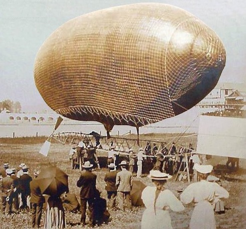
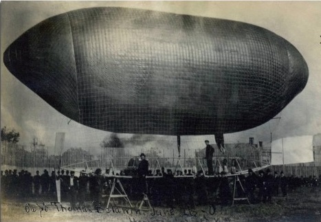
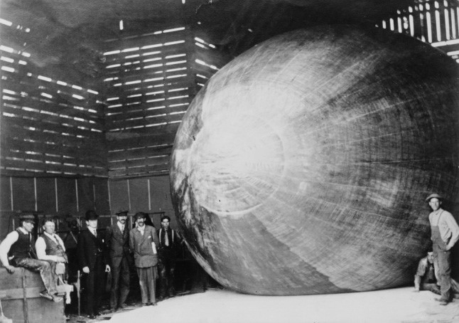
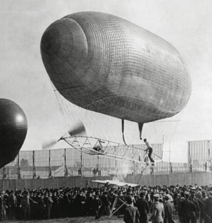
Works No: 6 ‘City of Portland’ was an exhibition airship designed, built, and owned by T.S.Baldwin.
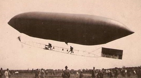
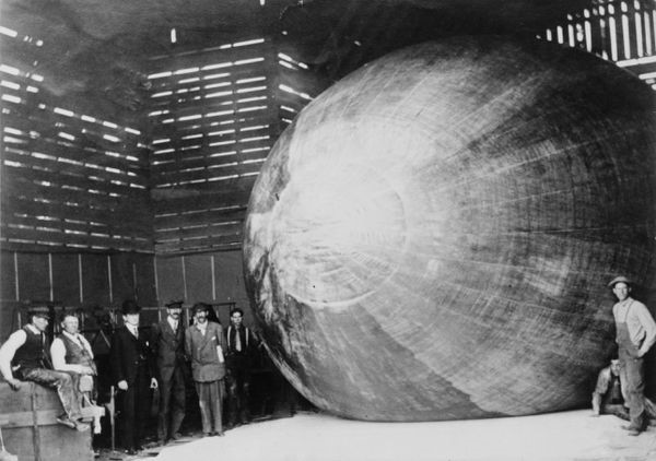
No.7 was a Baldwin-6 type touring airship of Capt. Hildebrandt, Berlin.
Designed and built by Capt. T.S.Baldwin at the Lewis & Clark Exposition sire aerodrome, ‘City of Portland’ was flown from 19 August until 2 September 1905 by the brothers Lincoln and Hillery Beachey. On 2 September the City of Portland was scheduled to race airship Gelatine, but because of strong winds its pilot, George Tomlinson, withdrew. Lincoln Beachey took off nether the less and was quickly swept across the river into Albina District. There he got caught up in a tree and tore a 10 ft hole in the side of the gasbag.
As a consequence of the catastrophic damage done to the envelope of City of Portland, coupled with the wear and tear from repeated flight to Gelatine’s gondola, the dirigibles were amalgamated; with the gasbag from the Gelatine being fitted onto the gondola of the City of Portland. This remodelled airship continued to carry the Gelatine name and flew for the duration of the fair.
Works No: 6 Name: Baldwin-6 Year: 1908 Length: 29.1 m Beam: 5.8 m Volume: 580 cu.m Engine: Curtiss, 20 hp Speed: 25 kph
Works No: 7 Name: H.1 Year: 1908 Length: 29.1 m Beam: 5.8 m Volume: 580 cu.m Engine: 20 hp Speed: 28 kph
Upon hearing about the first dirigible flights in France in 1898, Thomas Scott Baldwin traveled across the Atlantic to learn more. Unlike a hot-air balloon, which flies, literally, whichever way the wind takes it, a powered dirigible moves under its own power, and can therefore be taken exactly where you want it to go and can also return to where you start. Baldwin also sought the insight of the aviation pioneer and professor at Santa Clara College, John J. Montgomery, whose propeller designs were adopted by Baldwin, and August Greth, a French doctor living in San Francisco who had become fascinated by military observation balloons while serving in the French army in Algeria.
Baldwin began experimenting and ultimately built a non-rigid aircraft featuring a 52-foot-long, 17-foot-diameter gas bag of oiled Japanese silk that tapered to a point at both ends. The silk gas bag contained 8,000 cubic feet of hydrogen to keep the California Arrow aloft. It was a completely “basic” design, a suspended triangular frame catwalk as a “control car” under a set of square-mesh nets of strong cord which, upon inflation of the the gas bag, contain and held the gas bag captive. Baldwin constructed a 30-foot-long, triangulated-framed control car suspended from the gas bag by an extensive rope net. The control car had enough space for one man, the pilot, who could move fore and aft to shift himself as ballast as needed. The rudder was attached to this frame. The Gas-bag envelope was 54 feet long, the control “car” was made up of square cedar struts (painted a silver color resulting in an “aluminum” appearance) and piano wire cross bracing making the entire frame very rigid. The gas bag is cigar-shaped, made of Japanese silk “painted” with linseed oil to seal the silk and make it both impervious to gas, and relatively waterproof, had a capacity of 8,000 cubic feet of hydrogen.
What Baldwin did not have, and what he could not fabricate himself, was the appropriate engine. He found the right powerplant being made by a young motorcycle manufacturer in Hammondsport, New York, by the name of Glenn Hammond Curtiss. The compact and lightweight V-twin “Hercules” made between five and seven horsepower, enough to move the 520-pound dirigible under its own power, the output shaft of which was connected to a rudimentary propeller. The Curtiss engine weighed only 60 pound, and was located in the control car frame just forward of the center of gravity, and so geared as to generate 150 revolutions per minute at the propeller shaft. Though this was Curtiss’s first brush with the aviation industry, it would not be his last, as he would go on to found the very successful Curtiss Aeroplane and Motor Company, a leading U.S. aircraft manufacturer in the 1920s and early 1930s. The total weight of the airship was only 520 pounds, and had an estimated life capacity of about 500 pounds over the airship’s weight.
The altitude of Baldwin’s early airships was not regulated by means of a gas valve attached to the balloon. They had no valve. When the gas-bag is filled with hydrogen the neck of the gas inlet was simply tied-off with a piece of rubber. Elevation was provided by the volume of gas in the gas-bag, and the payload weight. Then after rising to a certain height the gas, which expanded due to the decrease in atmospheric pressure, would exert pressure against the constraint of the rubber tie around neck of the gas inlet. Overcoming the tie-off, some gas volume would be release allowing the machine to settle and stabilize at altitude. Of course, as the sun further heated the gas, the whole process would repeat, limiting the vehicle’s altitude and endurance.
Ascent and descent was affected by a weight which could be shifted from bow to stern, or vice-versa and permits the nose of the airship to be raised or lowered. The pilot could also scramble forward or aft on the gondola’s framework, thus subtracting of adding to the tilt of the nose. Using the thrust of the propeller alone, the airship was then “pulled” in the desired direction, though the pilot also had the luxury of reversing the rotation of the propeller if need. Directional turns were provided by a 5 by 3.5 foot rudder, which could be activated by the pilot from anywhere along the frame. Only about 20 pounds of ballast was carried for emergencies.
Constructors (left to right): Eugene Godet, Thomas Scott Baldwin, —, Glenn H. Curtiss.
Baldwin first flew the California Arrow in August of 1904, successfully completing a 20-block round trip in Oakland, California. With Lincoln Beachey as his pilot, the Arrow underwent the first controlled circular flight in America on August 3, 1904 at Idora Park in Oakland, California. But the real goal was to bring it to St. Louis for the Louisiana Exposition World’s Fair held that year. Organizers had secured sponsors for a $100,000 prize to be given to the first aircraft that could successfully navigate a predefined course and return to the start. A now overweight Baldwin hired another aviation pioneer, the much thinner and lighter Augustus Roy Knabenshue, to pilot the Arrow. Knabenshue won the prize for Baldwin, who garnered instant acclaim for creating the first successful self-propelled dirigible in the U.S. A 1905 Pope-Toledo touring car was the object of a “race” between the car and the airship.
First flown at Hammondsport, N.Y. on June 28, 1907 by Glenn Curtiss, Capt. Baldwin’s Curtiss-powered machine was driven by an a 4-bladed propeller and sported a rudder emblazoned with the “Stars and Stripes”. Often referred to as Baldwin Airship No.4, the dirigible was entered in the St. Louis airship races in October and finished a distant third behind the Strobel airships of Lincoln Beachey and Jack Dallas.
Baldwin and Knabenshue crisscrossed the country demonstrating the California Arrow, including racing Barney Oldfield across Los Angeles, with Oldfield confined to the ground in an automobile. Not long after, Baldwin secured contracts from both the Army and Navy to build their first dirigibles, based on what he had learned building the California Arrow.
Eventually, Baldwin and the crowds grew tired of this act as well, though Baldwin continued to work with hot-air balloons, even fabricating them in San Francisco.
On April 18, 1906, a massive earthquake struck San Fransisco. This was the great quake of 1906, and Thomas Baldwin’s manufacturing facility on Market Street was destroyed. He lost five airships including the California Arrow.
Baldwin California Arrow constructors (left to right): Eugene Godet, Thomas Scott Baldwin, —, Glenn H. Curtiss.
In 1902-1903 Thomas Scott Baldwin supervised the construction of the California Eagle based on the ideas of August Greth and financed by the American Aerial Navigation Company of San Francisco. It incorporated a French DeDion Bouton automotive engine and paddle propeller based on marine technology so prevalent in airship design in the period. After collaborating with Greth and John J. Montgomery in 1903-1904, Baldwin acquired sufficient knowledge to begin his own independent airship project.
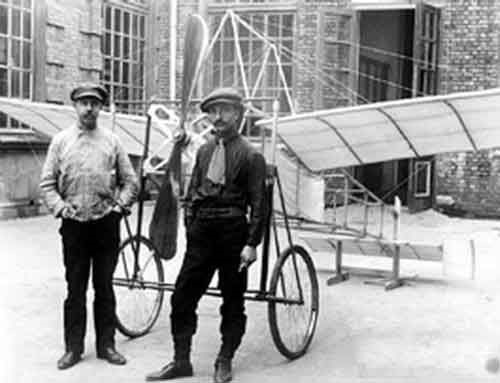
Built by a group of students at the polytechnic school of Baku (today Azerbaijan) in 1910. Based on Blériot’s famous monoplane, albeit a little smaller.
Increasing the wing area produces a noticeable increase in lift caused by the laws of aerodynamics. With more lift the crash speed becomes lower and therefore the aircraft can stay in the air with less “effort”. The increase in speed demands a decrease in the surface and therefore an increase in the load on each point of the wing.
Air combat aircraft seek to increase performance at the cost of greater driving power and a decrease in wing area, but even this type of aircraft is forced to carry out operations at low speeds such as approach and landing.
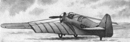
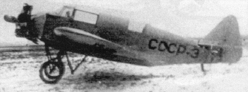
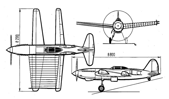
Aeronautical development has brought different solutions to this problem, among which the use of flaps and variable geometry in aviation stand out. In the 1930s in the USSR the aeronautical engineer Georgi Ivanovich Bakshayev proposed an interesting method to achieve the same effect. The practical implementation of his theory came to light in the form of the RK aircraft “Razdvizhnoe Krylo”, which was successfully tested in 1937.
The RK owes its name to the strange telescopic wing configuration (Razdvizhnoe Krylo – sliding wing), being also known as LIG-7 to indicate its development within the Leningrad Civil Aviation Fleet Institute. The main objective of this model was to obtain the smallest wing area for horizontal flight operations and its increase during takeoff and landing.
Designed as a conventional type two-seater monoplane with a 100 hp M-11 engine, this airplane was used as a test bed for a variable surface experimental wing. The RK was conceived as a low-wing monoplane aircraft braced by cables. This wing, made of wood, was characterized by having a wingspan of 11.3 meters, a constant chord (1.5 m) and a great aspect ratio, which allowed for improved performance during flight at cruising speed. With an M6 wing profile, the internal structure was designed on the basis of two wooden stringers. The covering was fabric. The wing featured bracing cables running from the top of the cabin and from a special cabin structure located in the ventral region.
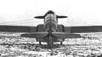
Rear view of the RK in configuration with the segments collected.
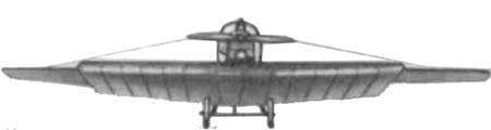
During takeoffs and landings, lift was increased by the extension of 6 telescopic sections, which increased the surface area of the wing to occupy two thirds of the wingspan, giving a total area of 23.85 sq.m. Each section, constructed of plywood, was 500mm wide with a 40mm overlap. The profile in this case was the TsAGI-846. The sections featured lightweight support ribs in the inner section constructed of pine and 2mm thick plywood overlay. The extension or retraction system was achieved by means of a steel cable that was operated manually from the cockpit. During the flight all sections were hidden inside the fuselage. The outer wing section with ailerons (one third of the wingspan) was not covered by the sections.
Front view of the RK in configuration with the segments extended.
The RK was ready for testing in 1937. The entire system worked well, with a retraction time of 20 to 30 seconds and extraction time of between 30 and 40 seconds. Retraction and extension were found to be easier in the air than on the ground.
The designers took overload and symmetry into account in the extraction / retraction process and this allowed for no negative effects during in-flight system testing. The center of gravity was established at 26% of the length.
The effect achieved during takeoff and landings was remarkable and the technology proved applicable. The speed did not increase considerably with the collected system, since it maintained a 20% resistance caused by the installation of the structure. Despite this, it was clear that the positive impact of this technology would be extremely useful on larger and faster aircraft, where resistance to wing advancement increases.
This advantage was of little use in civil aircraft. For this reason in 1938 Bakshayev proposed to develop an airplane to set speed records with this Klimov M-105 alar and power plant principle , but the project received no support, however an order was received to build a single-seater fighter using the Alar technology of the RK that was due to be ready for testing in 1940 and was known as Bakshayev RK-I (RK-800).
Engine: 1 x 100 hp M-11 piston engine Wingspan: 11.3m Length: 7.34 m Wingspan of extended sections: 6.27 m Wing area with retracted sections: 16.56 m² Wing area with extended sections: 23.85 m² Empty weight: 667kg Loaded weight: 897kg Wing load with sections retracted: 54.2 kg / m² Wing loading with extended sections: 37.6 kg / m² Power Load: 9.0kg / hp Fuel and oil weight: 70 kg Speed at sea level with sections retracted: 150 km / h Speed at sea level with extended sections: 144 km / h Landing speed with sections retracted: 100km / h Landing speed with extended sections: 75km / h Landing run with sections retracted: 210 m in 12 seconds Landing run with sections extended: 110m in 9 seconds Take-off run with sections retracted: 250m in 14 seconds Take-off run with sections extended: 135m in 9 seconds Range with sections retracted: 400 km Range with extended sections: 370 km Autonomy: 3.0 h Ceiling: 2900m Ascent time to 1000m: 7.5 minutes Ascent time to 2000m: 19.5 minutes Accommodation: 2
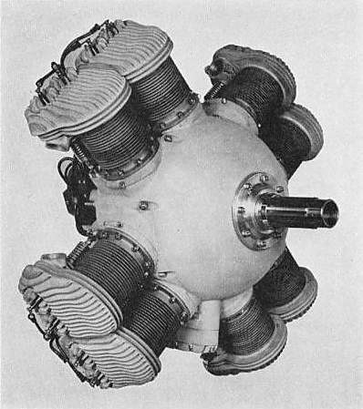
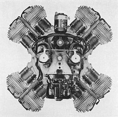
The Bakewell Wingfoot aero radial engine of 1939 consisted of four 90-degree V-twin engines, each with its own crankshaft, which was then geared to a common central propellor shaft. Propellor reduction gearing was fitted, the standard ratio being 1.57 to 1. This form of construction was claimed by the makers to give “inherent balance”.
The Bakewell engine was built by the Shaw-Palmer-Bakewell Co of Los Angeles.
The eight cylinders had a bore of 4in and a stroke of 4.5in, giving a displacement of 452 cu.in. (7407 cc) Output was claimed as 165 HP at 2800 rpm. The compression ratio was 5.4 to 1.
Circa 1964 mechanic Marion Baker utilised free flight models in the development of his MB-I Delta Kitten homebuilt experimental aircraft.
A tailless, Lippisch-like delta of all-metal construction and tricycle gear, the MB-1 was winner of EAA Design Trophy in 1961. The one built was registered N57A and cost $2,000 to build.
Those who flew the plane found it gentle and orthodox in response.
Horace Greeley Baker of Harlan, Iowa, USA, built this own design multiplane in 1911. The four wings were adjustable for maintaining lateral and longitudinal stability. A public demonstration was done at the Shelby County Fair in August 1911, but the huge machine was taken by a gust of wind and ended damaged in a fence, never to fly again.
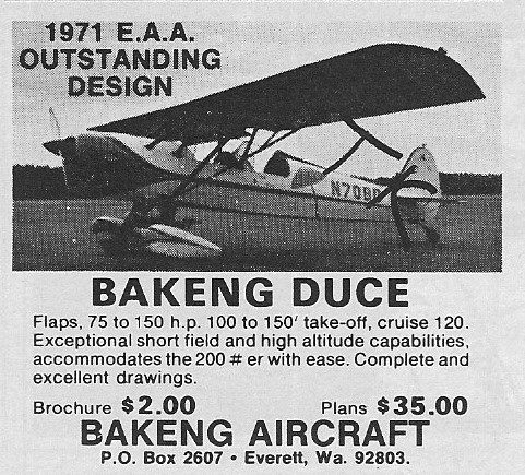
The Bakeng Deuce is a two-place parasol design utilizing a steel tube fuselage. The structure is faired with plywood and aluminum formers which support spruce stingers. Wings are of basic wooden construction with solid spruce spars.
First flown on 2 April 1970, this homebuilt received the ‘Outstanding New Design” and “Design improvement’ awards from the EAA in 1971. The V-strut braced wing utilizes both metal and spruce construction and is covered with fabric. The fuselage is also fabric-covered but is built from steel tubes. The landing gear is the conventional tailwheel type, and the two seats are arranged in tandem fashion. Bakeng has also designed a biplane version of the Duce, called the Double Duce. Both horizontally opposed and radial engines can be used, from 85-150 hp. Baking Deuce Airplane Factory purchased the rights to the Bakeng Duce in March of 1999. The name was changed to “Deuce” to separate those aircraft built before and after. The new Deuce incorporates the design of the old Duce with improvements based on analyzing the aircraft and listening to builders who have built and flown them for the past thirty years.
Dec 1973
Design Improvements are changes only to enhance integrity, reliability, ease of construction or function. These changes include: Beef up fuselage behind the landing gear legs. Complete redesign and relocation of the rudder pedals, cables and toe brakes. Complete redesign of the elevator control (pushrods instead of pulleys). Completely new lift strut attachments (individual, like old Pipers). Different tail mount structure New attachments for turtle deck Entirely new rudder design and mount (now removable). New method of attaching cross wire bracing in front of front cockpit. Removal of all elevator pulleys and cables. Larger fuel tanks Comfortable, factory-built bucket seats CAD drawings of the original plans have been completed.